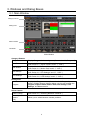
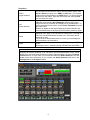
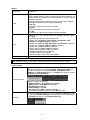
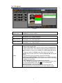
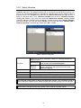
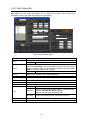
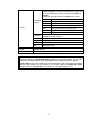
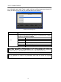
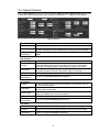
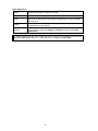
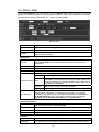
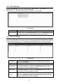
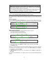
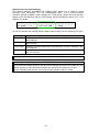
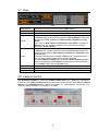
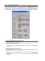
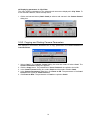
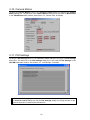
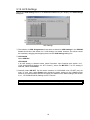
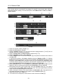
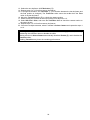
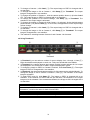
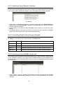
1
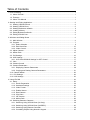
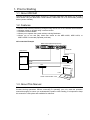
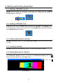
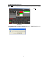
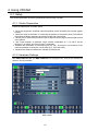
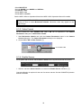
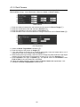
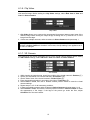
OPERATION MANUAL VRCAM Sensorless Virtual Studio System Version 2.2.2.0 – Higher Software License Agreement This Software License Agreement is a legally binding agreement between you (“User”) and FOR-A Company Limited (“Company”). The software, user manual and all other associated documentation (collectively, “Product”) are licensed, not sold, to the User. By installing and using the software, or by using a product of the Company in which the software is installed, User agrees to be bound by all terms and conditions of this agreement, as set forth below. 1. License Grant a. The Company grants User the license to use the Product in the manner specified in the user manual and other associated documentation. User may not use the Product in any manner other than specified. b. The Company only grants User the license to personally use the Product, and does not allow User to transfer the license to a third person or to enable a third person to use the Product by any other method. c. In principle, the software may only be used on a single computer or device. d. While the software may include various programs, they may not be unbundled and used as standalone programs. 2. Restrictions on Distribution, Duplication, Lease and Transfer User may not, without the Company’s prior permission, distribute via communication lines, or lease or transfer electronic copies of the Product, in whole or in part, nor attempt to do so. 3. Limitations of Guaranty The Company and its program licensors disclaim all legal warranties, express or implied, with respect to the Product. User must use the Product at own risk. In no event shall the Company and its program licensors be liable for any damage resulting from User’s use or inability to use the Product. 4. Provision of Upgrades and Updates Whenever the software is upgraded or updated, User may use the new version of the software by paying the amount separately specified by the Company. After upgrading the software, User may not use the earlier version without the Company’s prior permission. 5. Term of Validity of this Agreement This agreement shall be effective for a period of one year from the day User begins using the software. The same conditions of the agreement shall be extended for further one-year terms unless User or the Company expresses, at least one month prior to expiration of the agreement, the intent not to renew the agreement. 6. Termination of the Agreement a. The Company reserves the right to immediately terminate this agreement if User corresponds to either of the following circumstances. (1) User violates any terms of this agreement (2) User is unable or refuses to make the required payment b. User may terminate this agreement by written notice to the Company in the following circumstances, but may not seek a refund of the amount that User has already paid to the Company. (1) User waives the license (2) User destroys or loses the software package and prevents the Company from being able to confirm its existence c. After termination of this agreement, User may not use the Product in any way or form. 7. Ownership The Company and its program licensors retain all rights, including copyright and intellectual property rights, to the Product. User may not modify any program included in this software, nor disassemble, decompile, or reverse-engineer a program to analyze its source code. 8. Others This agreement will be governed by and construed in accordance with copyright laws and treaties in Japan and by laws and international treaties relating to intangible property rights. User must comply with all copyright laws and applicable laws and regulations when using the Product. 9. Jurisdiction Any dispute relating to the Agreement shall be subject to the jurisdiction of the Tokyo District Court. 10. Support If the Company discovers a flaw in the software or revises a program within one year after User receives the software, the Company will provide information regarding the flaw or revision or a revised program to User free of cost. VS-FlexGrid Pro 8.0J Copyright (C) 2001-2007 ComponentOne LLC. Upon Receipt Unpacking VRCAM Sensorless Virtual Studio System and its accessories are fully inspected and adjusted prior to shipment. Operation can be performed immediately upon completing all required connections and operational settings. Check your received items against the packing lists below. ITEM Installation CD-ROM Dongle USB extension cable Operation Manual QTY 1 1 1 1 REMARKS Check Check to ensure no damage has occurred during shipment. If damage has occurred, or items are missing, inform your supplier immediately. Table of Contents 1. Prior to Starting ........................................................................................................................ 1 1-1. About VRCAM ................................................................................................................... 1 1-2. Features ............................................................................................................................ 1 1-3. About This Manual ............................................................................................................ 1 2. Starting and Exiting Application ................................................................................................ 2 2-1. Starting VRCAM Launch ................................................................................................... 2 2-2. Starting VRCAM Cont ....................................................................................................... 2 2-3. Starting Brainstorm eStudio............................................................................................... 2 2-4. Loading eLibrary................................................................................................................ 2 2-5. Exiting Brainstorm eStudio ................................................................................................ 2 2-6. Exiting VRCAM Cont ......................................................................................................... 3 3. Windows and Dialog Boxes ...................................................................................................... 4 3-1. Main Window ..................................................................................................................... 4 3-2. Program............................................................................................................................. 7 3-2-1. Select Libraries........................................................................................................... 9 3-2-2. Edit Virtual Set.......................................................................................................... 10 3-2-3. Video Control............................................................................................................ 12 3-3. Adjust Camera................................................................................................................. 13 3-4. Motion Path ..................................................................................................................... 15 3-5. PIO Settings .................................................................................................................... 16 3-6. HVS Settings ................................................................................................................... 16 3-6-1. HVS-300HS/350HS Settings for XPT Control .......................................................... 17 3-7. View ................................................................................................................................ 19 3-8. Camera Control ............................................................................................................... 19 3-9. Camera Parameters ........................................................................................................ 20 3-9-1. Displaying Camera Parameters................................................................................ 20 3-9-2. Copying and Pasting Camera Parameters ............................................................... 21 3-10. Camera Motion .............................................................................................................. 22 3-11. PIO Settings .................................................................................................................. 22 3-12. HVS Settings ................................................................................................................. 23 4. Using VRCAM ........................................................................................................................ 24 4-1. Setup ............................................................................................................................... 24 4-1-1. Studio Preparation.................................................................................................... 24 4-1-2. Hardware Settings .................................................................................................... 24 4-1-3. Video Format ............................................................................................................ 25 4-1-4. Enable Sensor .......................................................................................................... 25 4-1-5. Real Camera ............................................................................................................ 26 4-1-6. Clip Video ................................................................................................................. 27 4-1-7. VR Camera .............................................................................................................. 27 4-1-8. Motion Path .............................................................................................................. 28 4-2. Switching Between Cameras........................................................................................... 30 4-2-1. Switching Using VRCAM Cont (OA Only) ................................................................ 30 4-2-2. Switching Using VRCAM Cont (OA/PREV) .............................................................. 30 4-2-3. Switching Using Remote Controller .......................................................................... 32 4-2-4. Controlling Playlist Using Numeric Keypad .............................................................. 32 4-2-5. Switching Using HANABI Virtual Link ....................................................................... 32 1. Prior to Starting 1-1. About VRCAM VRCAM Sensorless Virtual Studio System is a software application that allows you to build a virtual studio using the Brainstorm virtual camera, without the use of a virtual reality tracking device (sensor camera). 1-2. Features Allows virtual camera positioning changes using Virtual Link of the HANABI series switcher Allows a system to be built using a camera sensor OA/PREV mode available Allows you to operate the system without noticing Brainstom Allows you to cue and play video files saved on the MBP-100SX, MBP-110SX, or MBP-100PD if connected (separate purchase). Connection Example MBP-100SX (separate purchase) RS-232C SER.NO. AC100-240V 50/60Hz IN GPI/ALARM SDI IN SDI OUT VGA LAN2 LAN1 LAN Playout PC REMOTE GENLOCK IN USB4 USB3 REMOTE Camera MBP-1244 AUX2 AUX1 Hub Control PC LAN LAN Serial communication card COM4 1-3. About This Manual This manual is intended to help the user easily operate this product and make full use of its functions during operations. Before connecting or operating your unit, read this operation manual thoroughly to ensure you understand the product. After reading, it is important to keep this manual in a safe place and available for reference. 1 2. Starting and Exiting Application 2-1. Starting VRCAM Launch VRCAM Launch automatically starts when the playout PC is started. If the icon of VRCAM Launch does not appear on the taskbar on the playout PC, double-click the shortcut to VrCamLaunch on the desktop. 2-2. Starting VRCAM Cont Make sure that the icon of VRCAM Launch is displayed on the taskbar on the playout PC. On the desktop of the control PC, double-click the shortcut to VrCamGUI to start VRCAM Cont. If the same computer is used for playout and control, start VRCAM Cont on the same computer in which VRCAM Launch is installed. 2-3. Starting Brainstorm eStudio VRCAM automatically starts and closes Brainstorm eStudio. There is no need to start it manually. 2-4. Loading eLibrary VRCAM automatically loads eLibrary. There is no need to load eLibrary manually. 2-5. Exiting Brainstorm eStudio VRCAM automatically starts and closes Brainstorm eStudio. Normally, there is no need to close Brainstorm eStudio manually. To manually close Brainstorm eStudio, click the × button in the upper right corner of the GFX window. Click × GFX Window 2 2-6. Exiting VRCAM Cont Click the × button in the upper right corner of the VRCAM Cont main window to exit VRCAM Cont. Click × Main Window If Brainstorm eStudio is running on the playout PC, closing VRCAM Cont displays the following dialog box. To exit Brainstorm eStudio, click Yes. 3 3. Windows and Dialog Boxes 3-1. Main Window Category buttons Setting Area Select Camera Thumbnail Main Window Category Buttons Program Cam Params Cam Motion PIO Settings HVS Settings Displays Program in the setting area. (See section 3-2, “Program.”) Displays Adjust Camera and View in the setting area. (See section 3-3, “Adjust Camera” and 3-7, “View.”) Displays Motion Path and View in the setting area. (See section 3-4, “Motion Path” and 3-7, “View.”) Displays PIO Settings and View in the setting area. (See section 3-5, “PIO Settings” and 3-7, “View.”) Displays HVS Settings and View in the setting area. (See section 3-6, “HVS Settings” and 3-7, “View.”) Setting Area Program Select Camera Camera buttons (Cam1-Cam4) Camera position buttons (1-8) Displays the Program screen (See section 3-2, “Program.”) at startup. Clicking category buttons allows you to move between the Program, Adjust Camera, Motion Path, PIO Settings, HVS Settings, and View screens. Allows you to switch between cameras. (See section 4-2, “Switching Between Cameras.”) Allows you to switch between camera positions. 4 Thumbnail PREV (upper buttons) OA (lower buttons) Rows Swap Allows you to save camera positions. To save a camera position, use the right mouse button to drag a camera position button from Select Camera and drop it to a PREV or OA button. The camera position name is displayed on the PREV button. To clear a camera position from the button, right-click the button and choose Clear from the right-click menu. Displays thumbnails of camera positions. Right-clicking a PREV or OA button and choosing Set Thumbnail captures the current image from the GFX window and displays it on the OA button. To clear a thumbnail from a button, choose Clear Thumbnail from the right-click menu. *Noise may appear on the output image when the thumbnail is set. *If the thumbnail does not fit properly into the button, please try again. Allows you to select how many rows of thumbnail buttons to be displayed in the page. You can select a number from 1 through 4. There are 8 thumbnail buttons on each row. 32 buttons can be displayed at most. If you use all 32 thumbnail buttons of 4 rows, you can assign all camera positions to the buttons,. Allows you to switch between OA and PREV (if using OA/PREV mode). (See section 4-2-2, “Switching Using VRCAM Cont (OA/PREV).”) IMPORTANT Assigning all camera positions of all cameras to the thumbnail buttons on all 4 rows allows you to use the thumbnail buttons to switch camera positions in place of Camera position buttons. In such case, you can hide the buttons of Select Camera to use the limited screen more effectively, if you uncheck the Select Camera check box in the Setting Area on the Program screen. 5 Others Playout PC Load Save Save ipf Allows you to select the playout PC. Select OA or OA+PREV for normal use. Loads data from a .vrc file, .cam file, or .prg file. If the program differs from the current program when loading a .vrc file or .prg file, a message for confirming whether or not to change the library appears. Clicking Yes applies the data after changing the library. Clicking No applies the data without changing the library. .cam file: Information regarding cameras is included. .prg file: Information regarding a program is included. .vrc file: Information in .cam file and .prg file are both included. Saves data to a file. The file extensions available are .vrc, .cam, and .prg. The following status is not saved to the file. - Which one of Program, Cam Params, Cam Motion, PIO Settings, and HVS Settings is selected - Which one of Mouse Cam, Real Cam, and VR Cam is selected - Which one of LOCK, POS, and ORT is selected - Which one of HPR and PTZ is selected - Which camera (Cam1-Cam4) is selected - Which camera position (1-8) is selected - Which thumbnail button is selected - OA/NEXT status in the playlist - Mouse camera settings adjusted in GFX Issues a command for saving data to Brainstorm eStudio. After loading or saving a file, the file path is displayed in the title bar of the window. Lock Function To prevent accidental changes to the camera settings, you can disable the settings by choosing Disable Change Parameters in the right-click menu of the Cam Params, Cam Motion, PIO Settings, or HVS Settings button. To Enable the settings, choose Enable Change Parameters. Camera settings Save ipf When the button is disabled; - Adjust Camera in Cam Params is disabled. - Motion Path in Cam Motion is disabled. - PIO Settings is disabled. - HVS Settings is disabled. - VR Camera and GFX in View is disabled. - The camera selection mode is fixed to Recall mode. To prevent accidental changes, you can disable the Save ipf button by choosing Disable Save ipf in the right-click menu of the button. To Enable the button, choose Enable Save ipf. 6 3-2. Program Program Show/Hide check boxes Select Libraries Edit Virtual Set Video Control Direct Shows and hides Direct, Playlist, Text, Select Camera, and Thumbnail in the main window. Displays the Select Libraries dialog box. (See section 3-2-1, “Select Libraries.”) Displays the Edit Virtual Set dialog box. (See section 3-2-2, “Edit Virtual Set.”) Displays the Video Control dialog box. (See section 3-2-3, “Video Control”) Allows you to place command buttons that allows you to execute a command with a single click. To place a command button, drag and drop a button into Direct using the right mouse button. You can drop in camera position buttons from Select Camera or buttons from Control in the Edit Virtual Set dialog box. To remove a button from Direct, right-click a button and choose Remove from the right-click menu. Choosing Remove All removes all buttons. In the right-click menu you can also choose the following; Edit opens Command Editor, which allows you to edit the command. Set Thumbnail captures the current image from the GFX window and displays it on the button. Clear Thumbnail clears the thumbnail from the button. To move a button within Direct, left-click on and drag the button using your mouse while holding down the Ctrl key on the keyboard. *Overlapped buttons may not work properly. *Noise may appear on the output image when the thumbnail is set. *If the thumbnail does not fit properly into the button, please try again. 7 Playlist Text To add an item to Playlist, right-click on a button to drag and drop it into Playlist using your mouse. You can add command buttons from Direct, camera position buttons from Select Camera, or buttons in Control in the Edit Virtual Set dialog box. To remove an item from Playlist, right-click an item and choose Remove from the right-click menu. Choosing Remove All removes all items. In the right-click menu you can also choose followings; Edit from the right-click menu opens Command Editor which allows you to edit the command. Set Thumbnail captures the current image from the GFX window and displays it on the item in Thumbnail. Clear Thumbnail clears the thumbnail from the item. The order of items in Playlist can be changed by left-clicking on and dragging an item using your mouse while holding down the Ctrl key on the keyboard. The text in each column heading (Camera and Command) can be changed by clicking on the text and pressing the F2 key. *Noise may appear on the output image when the thumbnail is set. *If the thumbnail does not fit properly into the button, please try again. Plays the selected item in Playlist and selects the next item. OA is highlighted in red and NEXT is highlighted in green. The Enter key functions the same as the Take. Take The PageUP key moves the green highlight of NEXT to the item above the item currently selected for NEXT. The PageDown key moves the green highlight of NEXT to the item under the item currently selected for NEXT. Skips the item currently selected for NEXT in Playlist. Skip The + key on the numeric keypad functions the same as the Skip. Selects the top item in Playlist for NEXT. Top The Home key functions the same as the Top. Allows you to set texts. Select a text type object in Object in the Edit Virtual Set dialog box. The Text button in Control is enabled. To add an item to the list, right-click on the Text button to drag and drop it into Text using your mouse. To execute the event that is preset to the text that is added to the list, connect the event and the text in Text. To connect them, select the event in the Edit Virtual Set dialog box, and then right-click on the Event button under Control in the Edit Virtual Set dialog box to drag and drop it onto the text in Text. The order of items in the list can be changed by left-clicking on and dragging the item with your mouse while holding down the Ctrl key on the keyboard. The text in the column heading (Text) can be changed by clicking on the text and pressing the F2 key. Hide Link Displays Text and Note only. Show Link Displays Link in addition to Text and Note. Apply Allows you to apply the changes. Plays the selected item in Text and selects the next item. Take OA is highlighted in red and NEXT is highlighted in green. Skip Skips the item currently selected for NEXT in Text. Top Selects the top item in Text for NEXT. To use the numeric keypad to control the Playlist, NumLock must be off. 8 3-2-1. Select Libraries Clicking the Select Libraries button in Program in the main window displays the Select Libraries dialog box. This dialog box allows you to select and copy the libraries (scenes) you wish to use. The selected libraries are managed by program name. To copy a library, select a program name in the Program drop down list in Libraries Selected, and right-click on a library to drag and drop it from Libraries Available into the list in Libraries Selected. Clicking OK creates a copy and starts and loads Brainstorm eStudio. Clicking Cancel closes the dialog box without saving the settings. To delete a library from Libraries Selected, right-click a library in the list and choose Delete from the right-click menu. VRCAM_DBS in Libraries Selected is automatically added when OK is clicked. Select Libraries Dialog Box Program Enable Output Enable Sensor OK Cancel Allows you to specify destination folders for managing libraries by program name. To add a new program name to the drop down list, Add Program enter the text and click Add Program. To remove a program name from the drop down list, Remove select a program in the drop down list and click Program Remove Program. Enables and disables the SDI output. Enables and disables receiving the sensor data. Saves the changes and closes the dialog box. Closes the dialog box without saving the changes. The command prompt starts up along with Brainstorm eStudio. If the command prompt is closed, Brainstorm eStudio is also closed. Minimize the command prompt if you do not use it. Alphanumeric characters and some symbols can be used for program names. 9 3-2-2. Edit Virtual Set Clicking the Edit Virtual Set button in Program in the main window displays the Edit Virtual Set dialog box. This dialog box allows you to change the position, color, texture, text, show/hide, sound, and mask area settings for the objects. Edit Virtual Set Dialog Box DBS Event Object Sound Position Color Texture Text View Sound Mask Allows you to select a database. Displays the events in the selected database. Execute Allows you to execute events. Displays the objects in the selected database. Right-click the object and choose Set Mark to change the object name to blue. This can be used as a marker while you are working with objects. Choose Clear Mark to return the object name to black. Highlight Highlights the objects in the GFX window. Displays the sounds in the selected database. Allows you to set the scale, orientation, and position of objects. Allows you to set materials and colors. Allows you to specify texture files. Allows you to set text. Cull Allows you to show or hide the object. Allows you to set the rendering order. To set the order, Bin Order select the Enable Bin Order checkbox. Objects are layered in ascending order. Enable To set the rendering order, select this checkbox. Bin Order Allows you to specify audio files. Allows you to set the area of the mask objects. 10 Command buttons Control Transition Loop Play Stop Pause Play Update OK The command buttons in Control can be added to Direct or Playlist. To add a command button, right-click on a command button to drag and drop it into Direct or Playlist. *Clicking a command button in Control has no effect. Event Executes a given event. Position Changes the position to the given value. Color Changes the color to the given value. Texture Changes the texture to the given value. Text Changes the text to the given value. View Toggles between show and hide. Sound Changes the sound to the given value. Allows you to set the time spent for executing commands (value change). Allows you to play the movie repeatedly. Stops the sound. Pauses the sound. Plays the sound. Updates the list. Saves the settings and closes the dialog box. If the layer of objects in the virtual set does not appear as you expect, change the rendering order after selecting the Enable Bin Order checkbox to correct the problem. You can also change the rendering order to correct the appearance of translucent parts of objects. The Bin Order for the video wall is set at 100 as the default. If the video image on the video wall and other objects are not layered as you expect, select the Enable Bin Order checkbox and then set Bin Order for the object to a number larger than 101. 11 3-2-3. Video Control Clicking Video Control in Program in the main window displays the Video Control dialog box. If the MBP-100SX, MBP-110SX, or MBP-100PD is connected (separate purchase), this dialog box allows you to cue and play video files saved on the device. Video Control Dialog Box Item Control Displays the video files saved on the device. The command buttons in Control can be added to Direct or Playlist. To add a command button, right-click on a command button to drag and drop it into Direct or Playlist. Stop Stops the video. Pause Pauses the video. Cueup Cues the video. Play Plays the video. Cueup Play Cues and plays the video. OK Closes the dialog box. To enable the Video Control button in the main window, the value of MBP_VDCP_ENABLE under the [SETTING] section in the VrCamGUI.ini file, located in the same directory as VrCamGUI.exe, must be set to 1. The default value is 0. The files are received via LAN and control is performed via the serial interface. If the files are not displayed or control is not performed, check that all devices are properly connected. 12 3-3. Adjust Camera Clicking Cam Params in the main window displays Adjust Camera. Adjust Camera allows you to enter the camera position and video settings. See section 4-1, “Setup” for more details. Adjust Camera Camera No. Position No. Enable Sensor Copy Parameters Real Camera Dist. to Target Position Orientation Field of View Paste Parameters Displays the camera number selected in Select Camera. Displays the camera position number selected in Select Camera. Select this checkbox when using a sensor camera. See ifCalibSTD Manual for details on camera calibration and using a sensor camera. Copies parameters displayed in Real Camera, VR Camera, and Clip Video. Enter the distance between the real camera and a person. Enter the position of the real camera (X: left-right, Y: depth, Z: up-down) in the coordinate system having its origin at the origin of the studio (Normally, the target position is defined as the origin of the studio.). Enter the orientation of the real camera (X: pan, Y: tilt, Z: roll) in the coordinate system having its origin at the origin of the studio. Enter the field of view of the real camera. Pastes the copied Real Camera parameters. VR Camera Position Orientation Field of View Transition Paste Parameters Clip Video Horizontal Vertical Paste Parameters Enter the values of the virtual camera position in the relative value of the real camera position. Enter the values of the virtual camera orientation in the relative value of the real camera orientation. Enter the values of the field of view of the virtual camera in the relative value of the field of view of the real camera. Sets the motion duration of the virtual camera in seconds. Pastes the copied VR Camera parameters. Allows you to remove the left and right areas of the video image. Allows you to remove the top and bottom areas of the video image. Pastes the copied Clip Video parameters. 13 Auto Adjustment Show Target Select this checkbox to display a model. Model Height Enter the height of the person. If the real camera is focused on a person’s upper body, enter the height that is out of camera view (from foot to upper body). If it is a full body Offset shot, set to 0. Enter the values to align the yellow markers of the target model to the Position top and bottom of the person. Calculates the optimal values for Orientation Y and Field of View of Optimal the real camera using the Height and Position values under Auto Adjustment. To display objects over the video image sent from a camera, the rendering order must be changed at Bin Order. See 3-2-2. “Edit Virtual Set” for details on Bin Order. 14 3-4. Motion Path Clicking Cam Motion in the main window displays Motion Path. The motion path of the virtual camera is normally a straight line joining the two positions. By providing additional information, the path can be curved. See section 4-1, “Setup” for more details. Motion Path Camera No. From To Enable Displays the camera number selected in Select Camera. Allows you to select the original position of the virtual camera. Allows you to select the final position of the virtual camera. Select this checkbox to enable Motion Path. Disabling Motion Path makes the path straight. Keyframes Default Show Path Show Camera Transition Number of KFs KF Selection Clicking the Apply button returns the values in Position, Orientation, and Field of View to their default values and returns the path to a straight line. Displays the motion path on the output image. Displays the modeled virtual camera on the output image. Allows you to set the motion duration of the virtual camera in seconds. Displays the number of keyframes (64 keyframes maximum). Insert Inserts a keyframe before the currently selected keyframe. Adds a keyframe at the end and increases the value in Transition. The value after removing the Time value of the Add last keyframe from the original transition value is the amount increased in Transition. Remove Deletes the currently selected keyframe. Equally Places keyframes evenly on a straight path. Displays the keyframe number of the currently selected keyframe. (If the first keyframe is selected, 1 is displayed in the field.) The position, orientation, and field of view of the selected keyframe are displayed in Selected Keyframe. Click the < and > button to select a desired keyframe and set Position, Orientation, and Field fo View. Selected Keyframe Enter the coordinates of the currently selected keyframe (the keyframe Position with the number shown in KF Selection). Orientation Enter the orientation of the currently selected keyframe. Field of View Enter the field of view of the currently selected keyframe. Time Displays the time when the currently selected keyframe exists in seconds. Preview Enable Transition Select this checkbox for previewing the motion of the virtual camera. The appearance of the camera changes according to the slider position. 15 3-5. PIO Settings Clicking PIO Settings in the main window displays PIO Settings. PIO Settings allows you to assign functions to the buttons on the remote controller. See section 4-2-3, “Switching Using Remote Controller” for more details. PIO Settings Pin No. Icon List Items PIO input pin numbers. Enter the names of the Icon List items. You can also drag a camera position button from Select Camera and drop it into PIO Settings using the right mouse button to enter the name of the Icon List item. 3-6. HVS Settings Clicking HVS Settings in the main window displays HVS Settings. HVS Settings allows you to assign camera switching and camera position switching settings to the VR tallies of the HANABI series switcher See section 4-2-5, “Switching Using HANABI Virtual Link” for more details. HVS Settings XPT Control Tally No. Camera No. Position No. XPT No. Select the check box to enable the HVS-300HS/350HS crosspoint control via VRCAM GUI. VR tally numbers. Enter the camera numbers. You can also drag a camera position button from Select Camera and drop it into HVS Settings using the right mouse button to enter the camera number. Enter the position numbers. You can also drag a camera position button from Select Camera and drop it into HVS Settings using the right mouse button to enter the position number. If VR-XPT is selected for XPT No. Mode (3-12. HVS Settings ③), set the VIRTUAL XPT number (for example, VR01=1 and VR02=2) to which VR tally is set. If Button is selected for XPT No. Mode, enter the bus button number to which VIRTUAL XPT is assigned. 16 IMPORTANT VR-XPT may not work with the certain versions of HVS-300HS units. In such case, the editor interface (optional) must be used to control VRCAM via the HVS-300HS buttons. (For more details, contact our sales office.) For the settings to control VRCAM via the HVS-300HS/350HS buttons, see sections 3-6-1, “HVS-300HS/350HS Settings for XPT Control” and 3-12, “HVS Settings”. To assign a bus button number, select a number from 1 through 12. 3-6-1. HVS-300HS/350HS Settings for XPT Control The Ethernet and VR-Link settings of the HVS-300HS/350HS must be changed to use the XPT Control function. Please check the following settings if the XPT Control does not function. [Ethernet Settings] Go to the [SETUP - SYSTEM - ETHERNET] menu and check if the IP address and net mask are correct. See “Network Settings” in the HVS-300HS/350HS Operation Manual for details. SYSTEM : IP ADDRESS ETHERNET: =192.168.000.010 : : : 1/4 : SYSTEM : NET MASK ETHERNET: =255.255.255.000 : : : 2/4 : [Editor Interface (Optional)] If the HANABI editor interface is enabled, the editor setting is required. -HVS-300HS: [SETUP-EXT I/F-EDITOR] -HVS-350HS: [SETUP-FUNCTION-EDITOR] ① EDITOR : TYPE : = ② ③ :ENABLE :SELECT : WIPE : 1/2 : =ON : = : =NORML: ④ EDITOR :XPT CTL:WIP CTL:KEY CTL: : = : =ON : =ON : : 2/2 : ① For the HVS-300HS, select BVS3K for TYPE. For the HVS-350HS, select DVS. ② Set ENABLE to ON. Normally, the default settings are used for the following settings. For the certain versions of HVS-300HS units, the following settings are required when XPT No Mode is set to Button. ③ Set SELECT to other than PREV. ④ If XPT No Mode (see section 3-12, HVS Settings) is set to Button, set XPT CTL to BUTTON. For details on the EDITOR menu, see “Editor Control” in the HVS-300HS/350HS Operation Manual. 17 [Virtual Processor Input Settings] The [SETUP-VIRTUAL-ADVANCED-CG COMP] menu allows you to select a virtual processor input assignment. See “CG COMPONENT Menu” in the HVS-30VR/35VR Operation manual for details. When changing the TYPE setting, change the buss selection setting on the VRCAM along with the TYPE setting. See [Control Bus] in section 3-12, “HVS Settings” for details. VIRTUAL : COMPO : TYPE CG COMP : =1 : =FIX ME PGM :SHARED : 2/3 : =NON : To use VRCAM with the HANABI series switcher, select a type from the following four types. Setting FIX ME PGM FIX ME PST FIX PP PGM FIX PP PST Description Outputs composited video with a virtual set when VR XPT is selected on the M/E PGM bus. Outputs composited video with a virtual set when VR XPT is selected on the M/E PST bus. Outputs composited video with a virtual set when VR XPT is selected on the P/P PGM bus. Outputs composited video with a virtual set when VR XPT is selected on the P/P PST bus. For the HVS-300HS, select either FIX PGM or FIX PST for TYPE. IMPORTANT Do not select the setting other than the above four settings. Otherwise, the system may not operate properly or synchronization between the virtual set and video may be lost. On the HANABI series switcher, use P/P bus mode instead of A/B bus mode. 18 3-7. View View Mouse Cam Real Cam VR Cam Recall Store Enable VRCAM VR Camera GFX Displays the mouse camera view in the GFX window. Displays the real camera view in the GFX window. Displays the virtual camera view in the GFX window. Sets the camera selection mode to Recall. In Recall mode, clicking a camera button in Select Camera recalls and displays the stored parameters in Real Camera, VR Camera or Clip Video. If the value of Real Camera, VR Camera or Clip Video is changed in Recall mode, the change is applied to the camera that is currently selected in Select Camera. Sets the camera selection mode to Store. In Store mode, clicking a camera button in Select Camera stores the parameters displayed in Real Camera, VR Camera or Clip Video to the clicked button. If another camera button is clicked in Store mode, the parameters for the camera are also changed to the stored parameters. If another Camera Position button is clicked in Select Camera in Store mode, the parameter of VR Camera is changed to the stored parameter. To exit Store mode, click the Recall button. Select this checkbox to enable VRCAM. Drag the mouse to adjust the virtual camera position and orientation. Drag the mouse to adjust the mouse camera view in the GFX window. 3-8. Camera Control After Brainstorm eStudio is started, the Camera Control dialog box is displayed. The behavior of buttons in the Camera Control dialog box is the same as the buttons under View and Select Camera in the VRCAM Cont main window. See section 3-1, “Main Window” and section 4-2-1, “Switching Using VRCAM Cont (OA Only)” for details. 19 3-9. Camera Parameters Clicking the Camera Parameters button in the Camera Control dialog box displays the Camera Parameters dialog box. The parameters displayed in the Camera Parameters dialog box are the same as the parameters under Adjust Camera in the VRCAM Cont main window. (See section 3-9-1, “Displaying Camera Parameters” for details.) The camera parameters can be copied in Edit. (See section 3-9-2, “Copying and Pasting Camera Parameters” for details.) 3-9-1. Displaying Camera Parameters Displaying parameters in Real Camera Parameters of the selected real camera are displayed in Real Camera. To move between real cameras, follow the steps below. 1. Click a real camera button (Cam1-Cam4) to select a real camera in the Camera Control dialog box. Displaying parameters in VR Camera The parameters of the selected virtual camera are displayed in VR Camera. To move between virtual cameras, follow the steps below. 1. Click a real camera button (Cam1-Cam4) to select a real camera in the Camera Control dialog box. 2. Click a camera position button (1-8) to select a camera position in the Camera Control dialog box. 20 Displaying parameters in Clip Video The video clipping parameters of the selected real camera are displayed in Clip Video. To move between cameras, follow the step below. 1. Click a real camera button (Cam1-Cam4) to select a real camera in the Camera Control dialog box. 3-9-2. Copying and Pasting Camera Parameters The example in this section describes how to copy parameters from Cam1 Position1 to Cam2 Position1. 1. Select Cam1 in the Camera Control dialog box and then select 1 below Cam1. The Camera Parameters dialog box appears. 2. Click the Copy button. The parameters of Cam1 Position1 are copied to the buffer. 3. In the Camera Control dialog box, select Cam2 and then select 1 below Cam2. 4. In the Camera Parameters dialog box, click Paste to VR. The parameters of the Cam1 Position1 are copied to Cam2 Position1. 5. Click Paste to Real. The parameters of Cam1 are copied to Cam2. 21 3-10. Camera Motion Clicking the Camera Motion button in the Camera Control dialog box displays the Camera Motion dialog box. The behavior in the Camera Motion dialog box is the same as Motion Path in the VRCAM Cont main window. See section 3-4, “Motion Path” for details. 3-11. PIO Settings Clicking the PIO Settings button in the Camera Control dialog box displays the PIO Settings dialog box. The behavior in the PIO Settings dialog box is the same as PIO Settings in the VRCAM Cont main window. See section 3-5, “PIO Settings” for details. Left-clicking and dragging and dropping a camera button or camera position button from the Camera Control dialog box into the PIO Settings dialog box brings the item to the topmost empty line, instead of the selected line. 22 3-12. HVS Settings Clicking the HVS Settings button in the Camera Control dialog box displays the HVS Settings dialog box. ① ② ③ HVS Settings ① The behavior in HVS Assignments is the same as those for HVS Settings in the VRCAM Cont main window. See section 3-6, “HVS Settings” for details. However, the values cannot be entered by dragging and dropping them into this HVS Settings dialog box. ② HVS-300HS Select M/E Bus. HVS-350HS If an M/E setting is selected under Virtual Processor Input Settings (see section 3-6-1, “HVS-300HS/350HS Settings for XPT Control”), select the M/E Bus. If a P/P setting is selected, select the P/P Bus. ③ Normally select VR-XPT. On the certain versions of HVS-300HS units, VR-XPT may not work. In such case, select Button and change the editor setting on the HANABI series switcher (an optional editor interface required). For details on the editor settings, see section 3-6-1, “HVS-300HS/350HS Settings for XPT Control". If the optional editor interface is enabled, the editor setting is required. 23 4. Using VRCAM 4-1. Setup This section describes necessary preparations before using VRCAM. 4-1-1. Studio Preparation Follow the steps below for studio setup. Set up the equipment, including cameras, lightings, and a chromakey blue screen (green screen). Define the origin of the studio. It is normally the position of the person (host). This defines the positional relation between the graphic image and video image. Have a person stand at the position or put an object there having the same height as that of the person. Use a tape measure to measure rough camera coordinates (X, Y, Z) with X as the left-right, Y as depth, and Z as up-down coordinates. Estimate the orientation of the camera (pan, tilt, roll). This step is not necessary if the camera orientation is along the Y axis (enter [0, 0, 0] in that case). Measure the distance between the camera and the person. 4-1-2. Hardware Settings Start MBP-12Server.exe and MBP-12GUI.exe on the playout PC, and set the settings as shown in the figure below. MBP-12GUI 24 -Select MU SETUP. -Set both MIXER 1 and MIXER 2 to VIRTUAL. -Set DELAY to OFF. -Set V1 OUT to CG. -Set V2 OUT to CG KEY. See the MBP-12Server Operation Manual and MBP-12GUI Operation Manual for details. If you change VIDEO CONFIG settings in MBP-12GUI while Brainstorm eStudio is running, be sure to restart Brainstorm eStudio. Otherwise, noise may appear on the output image. 4-1-3. Video Format On the control PC, start VRCAM Cont. HD or SD can be specified in the Camera Parameters dialog box in Brainstorm estudio. 1. Start Brainstorm eStudio and click the Camera Parameters button in the Camera Control dialog box. The Camera Parameters dialog box is displayed. 2. Choose HD or SD in Video Format (①) ① Choose HD or SD 4-1-4. Enable Sensor For a system with a sensor, either Cam1 or Cam4 can be synchronized with the sensor. ① 1. Select a camera in Select Camera, and select the Enable Sensor checkbox (①). Camera calibration is required for the use of a sensor camera. See the ifCalibSTD Operation Manual for details. 25 4-1-5. Real Camera The example in this section describes how to set real camera settings. Before setting the Real Camera settings, select Real Cam in View and Cam1 in Select Camera. ① ② ③ ④ Real Camera 1. 2. 3. 4. Enter the distance between the real camera and the person in Dist. to Target (①). Enter the coordinates of the real camera in Position (②). Enter the orientation of the real camera in Orientation (③). Enter the field of view of the real camera in a range of about 30 to 50 in Field of View (④). ⑤ ⑥ ⑦ ⑧ ⑨ Auto Adjustment 5. Select the Show Target Model checkbox (⑤). 6. Enter the height of the person in Height (⑥). 7. If the real camera is focused on a person’s upper body, enter the height that is out of camera view (from foot to upper body) in Offset (⑦). 8. While viewing the output image, enter the values to align the yellow markers of the target model to the top and bottom of the person in a range of -0.5 to 0.5 in Position (⑧). 9. Click Calculate to the right of Optimal (⑨). The optimal values for Orientation Y and Field of View of the real camera are calculated. 10.If there are multiple cameras, select a camera in Select Camera and repeat steps 1 to 9. 11. Deselect the Show Target Model checkbox (⑤). 26 4-1-6. Clip Video The example in this section describes how to remove the unnecessary blue screen area of a real camera image. Before setting the Clip Video settings, select Real Cam in View and Cam1 in Select Camera. ① Clip Video 1. Clip Video allows you to remove the unnecessary blue screen (green screen) area of the camera image while viewing the output image. Entering 0.1 in ① removes 10 % of the image from the edge. 2. If there are multiple cameras, select a camera in Select Camera and repeat step 1. The Clip Video settings are not necessary for the camera that Enable Sensor has checked in Adjust Camera is checked. In this case, the clip setting is not applied even if the value is changed. 4-1-7. VR Camera The example in this section describes how to set the virtual camera settings. Before setting the VR Camera settings, select VR Cam in View and Cam1 in Select Camera. ① ② ③ ④ VR Camera 1. 2. 3. 4. 5. While viewing the output image, specify the position of the virtual camera in Position (①). Specify the orientation of the virtual camera in Orientation (②). Set the field of view of the virtual camera in Field of View (③). Enter the transition duration in seconds to the right of Transition (④). Select Store in View, and click a desired camera position button to store the virtual camera settings. 6. Repeat steps 1 to 5 for all necessary positions. 7. If there are multiple cameras, select a camera in Select Camera and repeat steps 1 to 6. 8. Select Recall in View, and click the camera position buttons in Select Camera to check the appearance of the image. If the legs of the person go under the floor, adjust Orientaion Y of the real camera. 27 4-1-8. Motion Path VRCAM can be used without setting the Motion Path settings. In such case, the motion path of the virtual camera is considered to be straight. To create a curved motion path, follow the steps below. Before creating a curved motion path, select Mouse Cam in View and Cam1 in Select Camera. ① ② ③ Motion Path ④ ⑤ ⑥ ⑦ ⑧ ⑨ ⑩ ⑪ ⑫ ⑬ Keyframes ⑮ ⑭ Preview 1. Select the original position in From (①). 2. Select the final position in To (②). 3. Select the Enable checkbox (③). The camera motion settings between ① and ② are not enabled unless this checkbox is selected. 4. Select the Show Path and Show Camera checkboxes (④, ⑤). 5. Select the Enable checkbox (⑭) in Preview. 6. Click the Apply button to create a default path (⑥). A keyframe is created on the center of a straight path. 7. To add a new keyframe, click Insert or Add to the right of Number of KFs (⑧). Clicking Insert adds a keyframe between the keyframe selected in KF Selection and the previous keyframe. Clicking Add adds a keyframe at the end and increases the Transition value so that the rates of change of the position and orientation against the duration remain the same. Clicking Equally replaces all keyframes evenly on a straight line. 8. Set KF Selection (⑬) to 1. The Position (⑨), Orientation (⑩), Field of View (⑪) and Time (⑫) values of the keyframe specified in KF Selection (⑬) are displayed. 9. While viewing the path on the output image, enter the Position values (⑨). If the path is not well shown, drag in GFX in View to adjust the view. The motion path is drawn with blue cones, and the keyframes appear as red cones. 10. While viewing the camera on the output image, set Orientation (⑩). The appearance of the camera changes according to the position of the Transition slider (⑮). 11. Adjust the field of view in FOV (⑪). 12. To set the time of a keyframe, enter the time code in seconds in Time (⑫). 28 13. Select the next keyframe in KF Selection (⑬). 14. Repeat steps 9 to 12 for all necessary keyframes. 15.To change the duration, set Transition ⑦. (The duration between the last keyframe and the final position is changed.) The Transition value cannot be smaller than the Time value of the last keyframe. 16. Move the Transition slider (⑮) to check the camera motion. 17. While viewing the camera on the output image, fine adjust 9 to 15. 18. Select VR Cam in View, and move the Transition slider to check the camera motion on the output image. 19. Repeat steps 1 to 18 for all necessary keyframes. 20. If there are multiple cameras, select a camera in Select Camera and repeat the steps 1 to 19. Checking Enable (⑭) in Preview enables the Transition slider (⑮). However, manually deselecting the checkbox does not disable the slider. Clicking a button in Select Camera automatically deselects Enable (⑭) and it disables the Transition slider. Enabling Transition may lower the rendering performance. 29 4-2. Switching Between Cameras This section describes how to switch between cameras and camera positions. 4-2-1. Switching Using VRCAM Cont (OA Only) Select Camera in VRCAM Cont allows you to switch between OA cameras and camera positions. ① ④ ② ③ Select Camera 1. To switch to Camera 1, click Cam1 (①). The output image is changed with a cut transition. 2. To change the position of Camera 1, click a desired camera position button (1-8) below Cam1 (②). The transition of the output image is animated. 3. To change the position of Camera 2 while Camera 1 is selected, click a desired camera position button (1-8) below Cam2 (③). In this case, the appearance of the output image does not change. 4. To change to Camera 2, click Cam2 (④). The output image is changed with a cut transition. 5. The method for switching between Camera 3 and Camera 4 is the same. 4-2-2. Switching Using VRCAM Cont (OA/PREV) Select Camera or Thumbnail in VRCAM Cont allows you to switch between OA and PREV cameras and camera positions. Using Select Camera ① ② ③ ④ Select Camera Thumbnail ⑤ 1. In Select Camera, the camera buttons and camera position buttons selected for OA output are displayed in red, and those for PREV output are displayed in green. The buttons selected for both OA and PREV are also displayed in green. 30 2. To change to Camera 1, click Cam1 (①). The output image on PREV is changed with a cut transition. 3. To change the image on OA to Camera 1, click Swap (⑤) in Thumbnail. The output image is changed with a cut transition. 4. To change the position of Camera 1, click the camera position button (1-8) below Cam1 (③). The output image on PREV is changed with a cut transition. 5. To change OA positions to the above settings, click Swap (⑤) in Thumbnail. The transition of the output image is animated. 6. To change the position of Camera 2 while Camera 1 is selected, click a desired camera position button (1-8) below Cam2 (④). In such case, the appearance of the output image will not change. 7. To change to Camera 2, click Cam2 (②). The output image on PREV is changed with a cut transition. 8. To change the image on OA to Camera 2, click Swap (⑤) in Thumbnail. The output image is changed with a cut transition. 9. The method for switching between Camera 3 and Camera 4 is the same. Using Thumbnail ② ① ③ Thumbnail ④ 1 In Thumbnail, you can select a number of rows to display from 1 through 4 Lines (①). Eight thumbnails are displayed on each row. Thirty-two thumbnails are available. 2. In Thumbnail, the camera buttons and camera position buttons selected for OA output are displayed in red, and those for PREV output are displayed in green. 3. To change the image on PREV to Camera1 Position2, click Cam1 Pos2 (②). The output image on PREV is changed with a cut transition. 4. In Thumbnail, the camera and camera position for OA output can be switched directly. To change the image on OA to Camera 1 Position 5, click (③). The transition of the output image is animated. 5. To swap PREV and OA, click Swap (④). The image on PREV is changed with a cut transition. If the cameras for PREV and OA are the same, the transition of the output image on OA is animated. If the cameras are different, the image on OA is changed with a cut transition. IMPORTANT Note that in OA/PREV mode Camera Parameters settings (See section 3-9, "Camera Parameters.") must be the same for both OA and PREV. You can also add camera positions to Direct or Playlist to switch between cameras. 31 4-2-3. Switching Using Remote Controller Using the remote controller allows you to switch between cameras and camera positions. Up to 16 functions can be assigned to the remote controller. Any function that has, its icon stored in the custom folder of Brainstorm eStudio, can be controlled via the remote controller. PIO Settings 1. Right-click on a desired camera button or camera position button from Select Camera to drag and drop it into PIO Settings to display the corresponding Icon List item on the line where the button is dropped. 2. Double-clicking a cell under the Icon List Items column allows you to enter the value directly. 3. Controlling a button on the remote controller connected to the input pin shown in Pin No. allows you to execute the item in the corresponding Icon List. 4-2-4. Controlling Playlist Using Numeric Keypad You can also control Playlist from the numeric keypad. See section 3-2,”Program” for details on Playlist. To control from the numeric keypad, set NumLock off. Enter Take Plays the selected item in Playlist and selects the next item. + Skip Skips the item currently selected for NEXT in Playlist. Home Top Selects the top item in Playlist for NEXT. Page Up - Selects the item above the item currently selected for NEXT. Page Down - Selects the item under the item currently selected for NEXT. 4-2-5. Switching Using HANABI Virtual Link Using Virtual Link of a HANABI series switcher allows you to switch between cameras linked via the crosspoint switching. Up to eight camera position buttons can be assigned to the Virtual Link tallies. See the HANABI Series Switcher Virtual Link Operation Manual for details on Virtual Link. 1. When a library (scene) is loaded, the connection between VRCAM and the HANABI series switcher is automatically established. There is no need to establish the connection manually. 32 2. Click HVS-Setting on the upper area of the window. Right-click on a desired camera position button from Select Camera to drag and drop it into HVS Settings to display the corresponding camera number and camera position number on the line where the button is dropped. 3. Double-clicking a cell under the Camera No, Position No, or XPT No. column allows you to enter the value directly. 4. Controlling a HANABI VR button, for which the tally shown in Tally No. is set, allows you to execute the corresponding camera position button. If XPT Control is enabled, the camera position can also be switched by the camera position buttons of Select Camera and by the thumbnail buttons. IMPORTANT Please do not press any button on the switcher while the camera mode is set to Store (see section 3-7, “View”). If you press any button on the switcher, return the camera mode to Recall and switch the camera using the switcher. Assigning cameras and camera positions in HVS Settings allows a position change for the switcher. If the switcher is operated during the position change, however, the source may be changed during the position change and an improperly composite image may be present. To avoid this, make sure the camera is completely switched before operating the switcher, or use the switcher only for camera switching and use an external remote controller to change the camera position. Setting only Camera No. and leaving Position No. blank disables the position change from the switcher. For the system with a sensor, leave Position No. blank in HVS Settings to assign a camera switch to a sensor camera. If the focus is on a numeric field in Cam Params or Cam Motion, the screen cannot be refreshed by the external request (for example, HANABI). This is to prevent unexpected changes to the values applied by other users. To refresh the screen, click a button in the main window of VRCAM Cont and remove the focus from the field. Although XPT Control is enabled, if a VIRTUAL XPT signal is selected in the HANABI, i.e., a tally signal of tally numbers 1 through 8 is output, the camera positions cannot be changed from the position shown in the HVS Setting by the XPT control. Camera position can be changed by the XPT control if a signal that is not assigned to VIRTUAL XPT is selected in the HANABI, i.e., a tally signal of tally number 0 is output. However, once the camera position is set to the position shown in the HVS Setting by the XPT control, further change will be disabled. 33 12/17/2010 Printed in Japan FOR-A COMPANY LIMITED Head Office Overseas Division Japan Branch Offices R&D/Production : 3-8-1 Ebisu, Shibuya-ku, Tokyo 150-0013, Japan Phone: +81 (0)3-3446-3936, Fax: +81 (0)3-3446-1470 : Osaka/Okinawa/Fukuoka/Hiroshima/Nagoya/Sendai/Sapporo : Sakura Center/Sapporo Center FOR-A America Corporate Office 11155 Knott Ave., Suite G&H, Cypress, CA 90630, USA Phone: +1 714-894-3311 Fax: +1 714-894-5399 FOR-A America East Coast Office Two Executive Drive, Suite 670, Fort Lee Executive Park, Fort Lee NJ 07024, USA Phone: +1 (201) 944-1120 Fax : +1 (201) 944-1132 FOR-A America Distribution & Service Center 2400 N.E. Waldo Road, Gainesville, FL 32609, USA Phone: +1 352-371-1505 Fax: +1 352-378-5320 FOR-A Corporation of Canada 346A Queen Street West, Toronto, Ontario M5V 2A2, Canada Phone: +1 416-977-0343 Fax: +1 416-977-0657 FOR-A Latin America & the Caribbean 5200 Blue lagoon Drive, Suite 760, Miami, FL 33126, USA Phone: +1-305-931-1700 Fax: +1-305-264-7890 FOR-A UK Limited UNIT C71, Barwell Business Park, Leatherhead Road, Chessington Surrey, KT9 2NY, UK Phone: +44 (0)20-8391-7979 Fax: +44 (0)20-8391-7978 FOR-A Italia S.r.l. Via Volturno 37, 20047 Brugherio MB, Italy Phone: +39 039 881086/881103 Fax: +39 039 878140 FOR-A Corporation of Korea 801 Dangsan Bld., 53-1 Dangsan-Dong, Youngdeungpo-Gu, Seoul 150-800, Korea Phone: +82 (0)2-2637-0761 Fax: +82 (0)2-2637-0760 FOR-A China Limited 708B Huateng Building, No. 302, 3 District, Jinsong, Chaoyang, Beijing 100021, China Phone: +86 (0)10-8721-6023 Fax: +86 (0)10-8721-6033 *The contents of this manual are subject to change without notice.


![TCR Operation manual[PDF:2MB] - FOR](http://vs1.manualzilla.com/store/data/005966473_1-1d77f66abea204b380154f66141da9f3-150x150.png)

![カタログPDFダウンロード[PDF:1.7MB]](http://vs1.manualzilla.com/store/data/006581727_2-bb010ce40f62d4b878607c76783fb901-150x150.png)
![VRCAM取扱説明書[PDF:2MB]](http://vs1.manualzilla.com/store/data/006716553_2-50d754f2a9ad4f3364dc2f0d5631e94e-150x150.png)
![SmartDirect取扱説明書[PDF:6.7MB]](http://vs1.manualzilla.com/store/data/006685208_2-aff58e80926c382fe1d043ce407b9aa2-150x150.png)
![MBP-12GUILE/12GUI取扱説明書[PDF:4.9MB]](http://vs1.manualzilla.com/store/data/006623918_2-b495e49e932502c0d2a50795758175dc-150x150.png)
![ifCalibSTD取扱説明書[PDF:549.2KB]](http://vs1.manualzilla.com/store/data/006720962_2-f6f093a08a8e1adf50f2443be8c61b6f-150x150.png)
![VTW Software Operation manual[PDF:17.4MB] - FOR](http://vs1.manualzilla.com/store/data/005725901_1-df2c6d7f9199f46fcf33ffa12e63545b-150x150.png)
![MBP-100PD取扱説明書[PDF:1.1MB]](http://vs1.manualzilla.com/store/data/006610502_2-39f3623fc3ee971ebb71a027b67a85fa-150x150.png)

![MBP-100SX取扱説明書[PDF:1MB]](http://vs1.manualzilla.com/store/data/006644318_2-a1d21a68db2015217897c9d9e4e2c978-150x150.png)


![UFM-30CTL Operation manual[PDF:4.1MB] - FOR](http://vs1.manualzilla.com/store/data/005676883_1-d2048345a5eb1a6d8c39e09dd604009b-150x150.png)