1
OPERATION MANUAL VRCAM2 Sensorless Virtual Studio System Version 1.3 or Higher Software License Agreement This Software License Agreement is a legally binding agreement between you (“User”) and FOR-A Company Limited (“Company”). The software, user manual and all other associated documentation (collectively, “Product”) are licensed, not sold, to the User. By installing and using the software, or by using a product of the Company in which the software is installed, User agrees to be bound by all terms and conditions of this agreement, as set forth below. 1. License Grant a. The Company grants User the license to use the Product in the manner specified in the user manual and other associated documentation. User may not use the Product in any manner other than specified. b. The Company only grants User the license to personally use the Product, and does not allow User to transfer the license to a third person or to enable a third person to use the Product by any other method. c. In principle, the software may only be used on a single computer or device. d. While the software may include various programs, they may not be unbundled and used as standalone programs. 2. Restrictions on Distribution, Duplication, Lease and Transfer User may not, without the Company’s prior permission, distribute via communication lines, or lease or transfer electronic copies of the Product, in whole or in part, nor attempt to do so. 3. Limitations of Guaranty The Company and its program licensors disclaim all legal warranties, express or implied, with respect to the Product. User must use the Product at own risk. In no event shall the Company and its program licensors be liable for any damage resulting from User’s use or inability to use the Product. 4. Provision of Upgrades and Updates Whenever the software is upgraded or updated, User may use the new version of the software by paying the amount separately specified by the Company. After upgrading the software, User may not use the earlier version without the Company’s prior permission. 5. Term of Validity of this Agreement This agreement shall be effective for a period of one year from the day User begins using the software. The same conditions of the agreement shall be extended for further one-year terms unless User or the Company expresses, at least one month prior to expiration of the agreement, the intent not to renew the agreement. 6. Termination of the Agreement a. The Company reserves the right to immediately terminate this agreement if User corresponds to either of the following circumstances. (1) User violates any terms of this agreement (2) User is unable or refuses to make the required payment b. User may terminate this agreement by written notice to the Company in the following circumstances, but may not seek a refund of the amount that User has already paid to the Company. (1) User waives the license (2) User destroys or loses the software package and prevents the Company from being able to confirm its existence c. After termination of this agreement, User may not use the Product in any way or form. 7. Ownership The Company and its program licensors retain all rights, including copyright and intellectual property rights, to the Product. User may not modify any program included in this software, nor disassemble, decompile, or reverse-engineer a program to analyze its source code. 8. Others This agreement will be governed by and construed in accordance with copyright laws and treaties in Japan and by laws and international treaties relating to intangible property rights. User must comply with all copyright laws and applicable laws and regulations when using the Product. 9. Jurisdiction Any dispute relating to the Agreement shall be subject to the jurisdiction of the Tokyo District Court. 10. Support If the Company discovers a flaw in the software or revises a program within one year after User receives the software, the Company will provide information regarding the flaw or revision or a revised program to User free of cost. VS-FlexGrid Pro 8.0J Copyright (C) 2001-2007 ComponentOne LLC. 2 Upon Receipt Unpacking VRCAM2 Sensorless Virtual Studio System and their accessories are fully inspected and adjusted prior to shipment. Operation can be performed immediately upon completing all required connections and operational settings. Check your received items against the packing lists below. ITEM QTY CD-ROM 1 Dongle 2 REMARKS Both VRCAM2 Proc and VRCAM2 Cont are included on the same CD-ROM Operation manual (PDF) One each for VRCAM2 Proc and VRCAM2 Cont Check Check to ensure no damage has occurred during shipment. If damage has occurred, or items are missing, inform your supplier immediately. 3 Table of Contents 1. Prior to Starting ...........................................................................................................................7 1-1. About VRCAM2 ....................................................................................................................7 1-2. Features ...............................................................................................................................7 1-3. About This Manual ...............................................................................................................8 2. Setup ...........................................................................................................................................9 2-1. Installing VRCAM2 ...............................................................................................................9 2-1-1. Installing Dongle Driver .................................................................................................9 2-1-2. Installing Windows Installer 3.1 ....................................................................................9 2-1-3. Installing .NET Framework 3.5 SP1 ............................................................................. 9 2-1-4. Installing Microsoft Visual C++ 2008 Runtime............................................................ 10 2-1-5. Installing VRCAM2 Cont (Control PC Only) ............................................................... 10 2-1-6. Installing VRCAM2 Proc (VRCAM2 Processor Only) ................................................. 10 2-2. Starting and Exiting Application .........................................................................................11 2-2-1. Starting VRCAM2 Launch ...........................................................................................11 2-2-2. Starting VRCAM2 Cont ...............................................................................................11 2-2-3. Starting Brainstorm eStudio ........................................................................................11 2-2-4. Loading eLibrary .........................................................................................................11 2-2-5. Exiting Brainstorm eStudio .........................................................................................11 2-2-6. Exiting VRCAM2 Cont.................................................................................................12 3. Windows and Dialog Boxes ......................................................................................................13 3-1. Main Window......................................................................................................................13 3-2. System Menu .....................................................................................................................14 3-3. Disabling Settings ..............................................................................................................17 3-4. Changing Parameters ........................................................................................................17 3-5. PROGRAM .........................................................................................................................18 3-5-1. Main Window...............................................................................................................18 3-5-2. DIRECT Pane .............................................................................................................19 3-5-3. PLAYLIST Pane ..........................................................................................................20 3-5-4. TEXT Pane..................................................................................................................23 3-5-5. SELECT LIBRARIES ..................................................................................................26 3-5-6. EDIT VIRTUAL SET....................................................................................................28 3-5-7. VIDEO CONTROL ......................................................................................................33 3-6. ADJUST CAMERA .............................................................................................................34 3-7. MOTION PATH ..................................................................................................................38 3-8. PIO Settings .......................................................................................................................42 3-8-1. PIO - SETUP ...............................................................................................................42 3-8-2. PIO - INPUT ASSIGN .................................................................................................43 3-8-3. PIO - OUTPUT ASSIGN .............................................................................................44 3-9. HVS Settings ......................................................................................................................47 3-9-1. HVS - SETUP..............................................................................................................47 3-9-2. HVS - TALLY ASSIGN ................................................................................................49 3-10. HOST Settings .................................................................................................................50 3-11. VIEW ................................................................................................................................51 3-12. SELECT CAMERA ...........................................................................................................54 3-13. THUMBNAIL ....................................................................................................................55 4 4. Changing Settings Through VRCAM2 Proc ............................................................................. 56 4-1. Camera Control ................................................................................................................. 56 4-2. Camera Parameters .......................................................................................................... 56 4-3. Camera Motion .................................................................................................................. 57 4-4. MC Effect ........................................................................................................................... 57 4-5. PIO Settings ...................................................................................................................... 58 4-6. HVS Settings ..................................................................................................................... 58 4-7. System Settings ................................................................................................................ 59 5. Using VRCAM2 ........................................................................................................................ 60 5-1. Setup ................................................................................................................................. 60 5-1-1. Studio Preparation ..................................................................................................... 60 5-1-2. Hardware Settings...................................................................................................... 60 5-2. Creating a Program ........................................................................................................... 61 5-2-1. Creating and Loading a Program ............................................................................... 61 5-2-2. Switching Between HD and SD ................................................................................. 62 5-2-3. ENABLE SENSOR ..................................................................................................... 62 5-2-4. REAL CAMERA.......................................................................................................... 63 5-2-5. CLIP VIDEO ............................................................................................................... 64 5-2-6. VR CAMERA .............................................................................................................. 65 5-2-7. DEFOCUS .................................................................................................................. 66 5-2-8. MOTION PATH .......................................................................................................... 67 5-3. Switching Between Cameras ............................................................................................ 69 5-3-1. Switching Through VRCAM2 Cont (OA Only) ........................................................... 69 5-3-2. Switching Through VRCAM2 Cont (OA/PREV) ......................................................... 70 5-3-3. Switching Through a Switch Box ............................................................................... 72 5-3-4. Controlling Playlist Through the Numeric Keypad ..................................................... 73 5-3-5. Switching Using HANABI Virtual Link ........................................................................ 73 5-4. Showing and Hiding Scenes ............................................................................................. 75 5-4-1. Showing a Scene ....................................................................................................... 75 5-4-2. Showing Multiple Scenes ........................................................................................... 75 5-5. Adding a Sound Effect to an Event ................................................................................... 76 6. HANABI Virtual Link System .................................................................................................... 77 6-1. HANABI Settings ............................................................................................................... 79 6-1-1. Ethernet Settings ........................................................................................................ 79 6-1-2. Camera Tally Signal Port Settings (HVS-350HS Only) ............................................. 79 6-1-3. Virtual Link Settings ................................................................................................... 79 6-1-4. Assigning a Virtual Crosspoint to a HANABI Button .................................................. 82 6-1-5. Editor Control Settings ............................................................................................... 82 6-2. MBP-12GUI Settings ......................................................................................................... 83 6-3. MBP-12Server Settings ..................................................................................................... 84 6-4. VRCAM2 Cont Settings ..................................................................................................... 85 6-4-1. Settings for HANABI Switcher Connection ................................................................ 85 6-4-2. VR XPT Settings ........................................................................................................ 86 6-4-3. Timing Adjustments.................................................................................................... 86 5 1. Prior to Starting 1-1. About VRCAM2 VRCAM2 Sensorless Virtual Studio System is a software application that allows you to build a virtual studio using the Brainstorm virtual camera, without the use of a virtual reality tracking device (sensor camera). 1-2. Features Maximum of four virtual cameras: Up to 32 positions can be set per camera. Sensored camera support: Enables mixed configurations using two of the four cameras as sensored cameras. OA/PREV mode available One-touch operation: Camera switching, subtitles, captions, scene transitions, among other scheduled actions, can be saved sequentially onto a playlist, and scene takes alone during a live program enable programmed timeline effects. Usage with a playlist enables the program timeline to be maintained while allowing composition changes and presentations that give a sense of actually being in the audience for live broadcasts. Defocus control: Enables effective presentation of background subject close-ups. Animation effects: A wide variety of animations (special effects) can be added for the subject. Linkage with the HANABI Series Video Switcher HVS-300HS/HVS-350HS (separate purchase) for assigning cameras and camera position selection to video switcher bus buttons and enabling control on the video swithcer-side. Allows you to cue and play video files saved on the MBP-100 Series MXF Clip Server (separate purchase). Connection Example MBP-100SX (separate purchase) RS-232C SER.NO. AC100-240V 50/60Hz IN GPI/ALARM SDI IN SDI OUT VGA LAN2 LAN1 LAN VRCAM2 Processor REMOTE GENLOCK IN USB4 USB3 REMOTE Camera MBP-1244 AUX2 AUX1 Hub Control PC LAN LAN Serial communication card 7 COM 1-3. About This Manual This manual is intended to help the user easily operate this product and make full use of its functions during operations. Before connecting or operating your unit, read this operation manual thoroughly to ensure you understand the product. After reading, it is important to keep this manual in a safe place and available for reference. 8 2. Setup 2-1. Installing VRCAM2 This section describes how to install the dongle driver, Microsoft Visual C++ 2008 Runtime, Windows Installer 3.1, .NET Framework 3.5 SP1, and VRCAM2 on the computer. If different computers are used for playout and control, .NET Framework 3.5 SP1 must also be installed on the control PC. In addition, if the operating system is Windows 7, there is no need to install Windows Installer 3.1 and .NET Framework 3.5 SP1 for both playout and control. 2-1-1. Installing Dongle Driver (1) Insert the supplied CD-ROM into the CD-ROM drive and double-click \License\SSDI751.exe in Windows Explorer to run the wizard. A User account confirmation dialog box may appear in Windows7. If one appears, click Yes to continue the installation. (2) Click Next. (3) Select I accept the terms in the license agreement and click Next. (4) Select Complete and click Next. (5) Click Install to start the installation. (6) After the installation is complete, click Finish. (7) Plug the license dongle into the USB port. If plugging the dongle in blocks the USB device connected to the adjacent port, use the supplied extension cord. When you first plug the dongle in, the screen as shown below is displayed. Select No, not this time and click Next. (8) Select Install the software automatically (Recommended) and click Next. (9) The screen as shown below is displayed. Click Continue Anyway. (10)Click Finish. The dongle driver installation is now complete. 2-1-2. Installing Windows Installer 3.1 The following procedure is required only for computers with the WindowsXP operating system. (1) If Windows Installer 3.1 (v2) is not installed on your computer, double-click \Microsoft\WindowsInstaller-KB893803-v2-x86.exe on the CD-ROM to run the wizard. (2) Click Next. (3) Select I agree and click Next. (4) After the installation is complete, you will be asked to restart your computer. Click Finish to restart your computer. 2-1-3. Installing .NET Framework 3.5 SP1 The following procedure is required only for computers with the WindowsXP operating system. (1) If .NET Framework 3.5 SP1 is not installed on your computer, double-click \Microsoft\dotnetfx35SP1.exe on the CD-ROM to run the setup wizard. (2) Select I have read and ACCEPT the terms of the License Agreement and click Install to start the installation. (3) After the installation is complete, click Exit. 9 2-1-4. Installing Microsoft Visual C++ 2008 Runtime The following procedure is required only for computers used for playout. (1) If Microsoft Visual C++ 2008 Runtime is not installed on your computer, double-click \Microsoft\vcredist_x64.exe on the CD-ROM to run the setup wizard. (2) Select I have read and ACCEPT the terms of the License Agreement and click Install to start the installation. (3) After the installation is complete, click Exit. 2-1-5. Installing VRCAM2 Cont (Control PC Only) (1) Insert the supplied CD-ROM into the CD-ROM drive on the control PC, and double-click \SetupVrcam2Cont.msi from My Computer in Windows Explorer to run the wizard. (2) Click NEXT three times consecutively when it appears on the respective pages. (3) After the installation is complete, click Close. 2-1-6. Installing VRCAM2 Proc (VRCAM2 Processor Only) (1) Insert the supplied CD-ROM into the CD-ROM drive on the VRCAM2 Processor, and double-click \SetupVrcam2Proc.msi from My Computer in Windows Explorer to run the wizard. (2) Click NEXT two times consecutively when it appears on the respective pages. (3) After the installation is complete, click Close. 10 2-2. Starting and Exiting Application 2-2-1. Starting VRCAM2 Launch VRCAM2 Launch automatically starts when the VRCAM2 processor is started. If the icon of VRCAM2 Launch does not appear on the taskbar on the VRCAM2 processor, double-click VrCam2Launch on the desktop. 2-2-2. Starting VRCAM2 Cont Make sure that the icon of VRCAM2 Launch is displayed on the taskbar on the VRCAM2 processor. On the desktop of the control PC, double-click VrCam2GUI to start VRCAM2 Cont. If the same computer is used for playout and control, start VRCAM2 Cont on the same computer in which VRCAM2 Launch is installed. 2-2-3. Starting Brainstorm eStudio VRCAM2 automatically starts Brainstorm eStudio. There is no need to start VRCAM2 manually. 2-2-4. Loading eLibrary VRCAM2 automatically loads eLibrary. There is no need to load eLibrary manually. 2-2-5. Exiting Brainstorm eStudio VRCAM2 automatically closes Brainstorm eStudio. Normally, there is no need to close Brainstorm eStudio manually. To manually close Brainstorm eStudio, click the × button in the upper right corner of the GFX window on the VRCAM2 processor. Click × GFX Window 11 2-2-6. Exiting VRCAM2 Cont Click the × button in the upper right corner of the VRCAM2 Cont main window to exit VRCAM2 Cont. Click × Main Window If Brainstorm eStudio is running on the VRCAM2 processor, exiting VRCAM2 Cont displays the following dialog box. Click Yes to exit both VRCAM2 Cont and Brainstorm eStudio. Click No to exit VRCAM2 Cont without exiting Brainstorm eStudio. Click Cancel to cancel exiting VRCAM2 Cont. 12 3. Windows and Dialog Boxes 3-1. Main Window After VRCAM2 Cont is started, the screen as below appears. The VRCAM2 Cont main window consists of four panes. ① System menu ② Setting area ③SELECT CAMERA pane ④THUMBNAIL pane Main Window ① System menu Allows you to show and hide the SELECT CAMERA pane and THUMBNAIL pane, select the VRCAM2 processor, and save and load settings. ② Setting area The tabs at the top allow you to select a category and view the corresponding screen. After the VRCAM2 Cont is started, the PROGRAM tab will be selected. ③ SELECT CAMERA pane Allows you to switch between the virtual cameras and positions. ④ THUMBNAIL pane Allows you to assign virtual cameras and positions to the PREV buttons (upper buttons), and thumbnails to the OA buttons (lower buttons). 13 3-2. System Menu System menu allows you to show and hide the SELECT CAMERA pane and THUMBNAIL pane, select the VRCAM2 processor, and save and load settings. ① Show/hide ② VRCAM2 processor selection ③ Save and load data System Menu ① Show/hide Allows you to show and hide the SELECT CAMERA pane and THUMBNAIL pane. The pane that can be shown and hidden on each page differs as below. CAM CAM PROGRAM PIO HVS SETUP PARAMS MOTION SEL CAM THUMBNAIL ② VRCAM2 processor selection Allows you to select the VRCAM2 processor to be controlled through VRCAM2 Cont. The top item (OA or OA+PREV) should be selected as standard. To view and change the VRCAM2 processor settings, select the SETUP tab. (See section 3-10. “HOST Settings.”) IMPORTANT - If a single VRCAM2 processor is selected when two VRCAM2 processors are selected (OA/PREV mode), HANABI Virtual Link will not be available. -If HANABI Virtual Link is used, set PORT to CLOSE and XPT CONTROL to DISABLE. See section 3-9-1. “HVS - SETUP” for details. ③ Save and load settings VRCAM2 Cont have two save options: SAVE and SAVE IPF. Save Option SAVE SAVE IPF Description Saves the VRCAM2 settings to a file. Once the camera settings are saved to a file, they can be used for other scenes. To load the settings, click LOAD. Saves the program data. Loading the saved program data recovers the settings to the last time it was saved. Use this option after creating program data in VRCAM2 Cont. The thumbnail images in DIRECT, PLAYLIST, and THUMBNAIL are saved with the SAVE IPF button only. 1. SAVE and LOAD Clicking the SAVE button displays the Save As dialog box. Selecting the file format, enter the file name, and clicking OK saves the settings with the selected file format. 14 File Format .prg2 .cam2 .vrc2 .prg .cam .vrc Description The DIRECT, PLAYLIST, and TEXT pane settings under PROGRAM are saved. (See section 3-5. “PROGRAM.”) Note that the OA/NEXT selection status in the playlist is not saved. The CAM PARAMS (see section 3-6. ADJUST CAMERA) and CAM MOTION (see section 3-7. MOTION PATH) settings are saved. The settings included in .prg2 file and .cam2 file are both saved. The VRCAM file format. The VRCAM file format. The VRCAM file format. IMPORTANT If the VRCAM data is loaded into VRCAM2, part of the data may be converted. Before using the data loaded from VRCAM, check its content. Clicking the LOAD button displays the Open dialog box. Selecting a file and clicking Open loads the file. If you load a .prg2 or .vrc2 file that differs from the currently opened program, a confirmation message for changing the library appears. Clicking Yes changes the library and applies the loaded data. Clicking No applies the loaded data without changing the library. Clicking Cancel cancels loading data. 2. SAVE IPF Left-clicking the SAVE IPF button saves the Brainstorm eStudio data to the VRCAM2 processor. It overwrites the selected program with the current settings. To load the saved program data, select a program in SELECT LIBRARIES. (See section 3-5-5. “SELECT LIBRARIES.”) Right-clicking the SAVE IPF button and choosing Disable Save Ipf disables the button. Selecting Enable Save Ipf enables the button. 15 NOTE The following VRCAM2 Cont settings are not saved to a file. - Which one of PROGRAM, CAM PARAMS, CAM MOTION, PIO, HVS, and SETUP is selected - Which one of MOUSE CAM, REAL CAM, and VR CAM is selected - Which one of LOCK, POS, and ORT is selected - Which one of HPR and PTZ is selected - Which camera (Cam1-Cam4) is selected - Which camera position (1-32) is selected - Which thumbnail button is selected - OA/NEXT status in the playlist - Mouse camera settings adjusted in GFX 16 3-3. Disabling Settings To prevent accidental changes, you can disable some settings. Disabled Settings Description Right-clicking the CAM PARAMS, CAM MOTION, PIO, HVS, or SETUP button and choosing Disable Change Parameters disables settings. Choosing Enable Change Parameters from the right-click menu enables the settings again. General settings The following settings will be disabled. -ADJUST CAMERA under CAM PARAMS -MOTION PATH under CAM MOTION -VR CAMERA and STORE in VIEW -PIO -HVS-SETUP Right-clicking the SAVE IPF button and choosing Disable Save Ipf disables settings. Choosing Enable Save Ipf from the right-click menu enables the settings again. SAVE IPF The checkboxes below allow you to disable system settings. Once tested, it is recommended to disable these settings since they are not used during normal operation. (They are automatically disabled after the software is started.) PIO Settings HVS Settings HOST Settings Unchecking the EDIT checkbox under PIO > SETUP disables SETUP setting changes. Unchecking the EDIT checkbox under HVS > SETUP disables SETUP setting changes. Unchecking the EDIT checkbox under SETUP disables SETUP setting changes. 3-4. Changing Parameters In VRCAM2 Cont, parameters can be changed as below, in addition to directly changing numeric values. 1. Click to select a digit you wish to change using the left mouse button. 2. Click the upper button next to the value to increase the digit by 1, and the lower button to decraese it by 1. 3. Use your mouse wheel to change the value. 4. Use the up and down arrow keys to increase and decrease the value, and left and right arrow keys to move between digits. 17 3-5. PROGRAM 3-5-1. Main Window Select the PROGRAM tab to display the PROGRAM pane. ⑤SELECT LIBRARIES ⑥EDIT VIRTUAL SET ① Show/hide ② DIRECT pane ⑦VIDEO CONTROL ③PLAYLIST pane ④TEXT pane PROGRAM pane ① Show/hide Allows you to show and hide the DIRECT, PLAYLIST, and TEXT panes under the PROGRAM pane. ② DIRECT pane Allows you to place command buttons that enable you to switch cameras or start and stop an event with a single click. See section 3-5-2. “DIRECT Pane” for details. ③ PLAYLIST pane Allows you to create a playlist. Camera switching and events can be saved sequentially onto a playlist, and scene takes alone during a live program enable programmed timeline effects. (See section 3-5-3 “PLAYLIST Pane.”) The DIRECT pane allows an operator to execute an event at the desired timing even while the playlist is running. ④ TEXT pane Allows you to set text for captions. It can also be used as a playlist. (See section 3-5-4 “TEXT Pane.”) ⑤ SELECT LIBRARIES button Clicking the SELECT LIBRARIES button displays the SELECT LIBRARIES dialog box. (See section 3-5-5. “SELECT LIBRARIES” for details.) ⑥ EDIT VIRTUAL SET button Clicking the EDIT VIRTUAL SET button displays the EDIT VIRTUAL SET dialog box. (See section 3-5-6. “EDIT VIRTUAL SET” for details.) ⑦ VIDEO CONTROL button Clicking the VIDEO CONTROL button while MBP-100SX, MBP-110SX, or MBP-100PD (separate purchase) is connected displays the VIDEO CONTROL dialog box. (See section 3-5-7. “VIDEO CONTROL” for details.) 18 3-5-2. DIRECT Pane Allows you to add command buttons that enable you to switch cameras or start and stop an event with a single click. To add a command button, drag and drop a button into the DIRECT pane using the left mouse button. Up to 64 buttons can be added to the DIRECT pane. Drag From SELECT CAMERA pane EDIT VIRTUAL SET dialog box TEXT pane Buttons That Can Be Added to the DIRECT Pane CAM1 through CAM4 buttons CAM1 through CAM4 position buttons (1 to 32) Buttons in the CONTROL pane (EVENT, POSITION, COLOR, TEXTURE, TEXT, VIEW, STOP, PAUSE, PLAY, SOUND, VOLUME, SCENE CHG, MC IN1 through MC IN3, MC OUT1 through MC OUT3, IN EFFECT1 through IN EFFECT9, OUT EFFECT1 through OUT EFFECT9 buttons) Group item in the list. To move or resize the added button, left-click on and drag the button using your mouse. (Drag to resize the edge of the button.) In addition, the following right-click menus are available. Right-Click Menu New button Edit command Set thumbnail Remove thumbnail Remove Remove all Description Allows you to create an empty button. Allows you to edit the command to be executed when the button is clicked. For details on external device control using PIO output, see section 3-8-3. “PIO - OUTPUT ASSIGN”. Captures the current image from the GFX window and displays it on the button. Removes the thumbnail from the button. Removes the selected command button from the DIRECT pane. Removes all command buttons from the DIRECT pane. NOTE Overlapped buttons in the DIRECT pane may not work properly. Noise may appear on the output image when setting a thumbnail to a command button. 19 3-5-3. PLAYLIST Pane To create a playlist, left-click on a button to drag and drop one of the buttons shown in the below table into PLAYLIST using the left mouse button. Pressing the F2 key while selecting an item in the playlist allows you to enter comments under CAMERA and COMMAND. Thumbnails and comments help operators during scene takes. Up to 64 items, including the green-highlighted items with the group name displayed, can be added to the playlist. Drag From SELECT CAMERA pane EDIT VIRTUAL SET dialog box DIRECT pane TEXT pane Buttons That Can Be Added to the PLAYLIST Pane CAM1 through CAM4 buttons. CAM1 through CAM4 position buttons. (1 to 32) To change a camera and its position simultaneously, (for example, switching to CAM2POS4,) the camera and position must be changed in one take. In such case, Group can be used. Buttons in the CONTROL pane. (EVENT, POSITION, COLOR, TEXTURE, TEXT, VIEW, STOP, PAUSE, PLAY, SOUND, VOLUME, SCENE CHG, MC IN1 through MC IN3, MC OUT1 through MC OUT3, IN EFFECT1 through IN EFFECT9, OUT EFFECT1 through OUT EFFECT9 buttons) Command buttons placed in the DIRECT pane. The TAKE, SKIP, TOP buttons and Group item in the list The OA item in the playlist will be highlighted red and the NEXT item highlighted green. The items that will be sequentially executed with the next take will all be highlighted green. -Press the Page UP key to move the green-highlighted NEXT item selection one line up. -Press the Page Down key to move the green-highlighted NEXT item selection one line down. In addition, the following shortcut keys are available for the created playlist. Function Button Take TAKE Skip SKIP Top TOP Back - Description Plays the current NEXT item in the playlist and sets the next item as the NEXT item. Skips the current NEXT item and sets the next item as the NEXT item. Sets the top item in the playlist as the NEXT item. Without playing the current NEXT item in the playlist, sets the previous item as the NEXT item. 20 Shortcut Key Enter + Page Down Home - Page Up ■Menu The following right-click menus are available. Right-Click Menu Edit command Set thumbnail Remove thumbnail Remove Remove all Insert Group Item Description Allows you to edit the label of the selected item and the command to be executed when the TAKE button is clicked. For details on external device control using PIO output, see section 3-8-3. “PIO - OUTPUT ASSIGN”. Captures the current image from the GFX window and displays it on the button. Removes the thumbnail from the button. Removes the selected item button from PLAYLIST. Removes all items from PLAYLIST. Allows you to save multiple tasks as a group so that they can be executed in one take. Clicking the arrow button next to the group name displays the group name only. ■ Changing Item Order There are two ways to change the item order. Changing Item Order Using UP and DOWN Buttons Clicking the UP or DOWN button while an item is selected moves the item one position up or down. If a green-highlited group name is selected, the whole group can be moved. Items cannot be move into or out of a group using the UP or DOWN buttons. Changing Item Order by Dragging Items To move an item out of a group, drag the item using the left mouse button. When dragging an item, a blue horizontal line that indicates the insertion position will appear between items into where the item will be dropped. While dragging an item, the PLAYLIST cannot be scrolled. ■ Group Group is a useful function that allows multiple items to be executed in one take. Note the following usage details. -If a position change is included in the command, the next item will not be executed until the camera is completely moved. -Only items under the lowest level are executed sequentially. For example, if Group 2 is created inside Group 1, items in Group 1 will not be executed sequentially. -If no group is saved in the list, all items are considered to be under the lowest group and, therefore, are executed sequentially. To avoid doing so, create at least one group with an item. Take1: Switched to CAM1POS1 (camera and position) Take2: Switched to CAM1POS2 (position only) Take3: Switches virtual set Switched to CAM2POS2 (camera and position) Take4: Switched to CAM2POS2 (position only) 21 NOTE Noise may appear on the output image when setting a thumbnail to an item in the playlist. If the thumbnail does not fit properly into the button, please try again. To use the numeric keypad to control the Playlist, the NumLock key must be off. When the OA or NEXT item is moved, red or green highlight coloring may not apply correctly. In such case, select the top item in the playlist as the Next item to reset the highlight colors. 22 3-5-4. TEXT Pane The TEXT pane allows you to set text for captions. Selecting a text type object under OBJECT in the EDIT VIRTUAL SET dialog box enables the TEXT button in the CONTROL pane. To add an item to the list, drag and drop the TEXT button into the TEXT pane using the left mouse button. Up to 64 items, including the green-highlighted items with the group name displayed, can be added to the TEXT pane. The text object added to the list can be linked to an event. To link to an event, first select an action in the FOLDER/ACTION LIST under EVENT, and then drag and drop the EVENT button from the CONTROL pane onto the text previously added in the TEXT pane, using the left mouse button. Draging an item in the list using the left mouse button allows you to change the order. Clicking the heading “TEXT” in the list and pressing the F2 key allows you to edit the label. Changes will be applied when TAKE is performed, and the text in the STRING in the TEXT pane in EDIT VIRTUAL SET will be updated. If TAKE is performed for text with no linked event, the text will still be updated. 23 The OA item in the TEXT pane will be highlighted red and the NEXT item highlighted green. Items that will be sequentially executed with the next take will all be highlighted green. The following three buttons are available for the created TEXT. Button TAKE SKIP TOP Description Plays the current NEXT item in the TEXT pane and sets the next item as the NEXT item. Skips the current NEXT item in the TEXT pane and sets the next item as the NEXT item. Sets the top item in the TEXT pane as the NEXT item. These three buttons can be added by dragging and dropping into PLAYLIST using the left mouse button. By doing this, text can be output with intended timing through PLAYLIST. ■ Menu The following right-click menus are available for the text in the list. Right-Click Menu Remove Remove all Insert Group Item Import CSV Description Removes the selected item from the TEXT pane. Removes all items from the TEXT pane. Allows you to save multiple tasks as a group so that they can be executed in one take. Clicking the arrow button next to the group name displays the group name only. Allows you to load text from the selected CSV file. ■ Changing Item Order There are two ways to change the item order. Changing Item Order Using UP and DOWN Buttons Clicking the UP or DOWN button while an item is selected moves the item one position up or down. If a green-highlited group name is selected, the whole group can be moved. Items cannot be move into or out of a group using the UP or DOWN buttons. Changing Item Order by Dragging Items To move an item out of a group, drag the item using the left mouse button. When dragging an item, a blue horizontal line that indicates the insertion position will appear between items into where the item will be dropped. While dragging an item, the TEXT pane cannot be scrolled. ■ Group Group is a useful function to execute multiple items in one take. Note the following usage details. -Only items under the lowest level are executed sequentially. For example, if Group 2 is created inside Group 1, the items in Group 1 will not be executed sequentially. -If no group is saved in the list, all items are considered to be under the lowest group and, therefore, are executed sequentially. To avoid doing so, create at least one group with an item. A Group item in the TEXT pane can be added by dragging and dropping into the PLAYLIST or DIRECT pane using the left mouse button. By doing this, in the PLAYLIST and DIRECT panes, text can be processed regardless of the order in the TEXT pane. 24 ■ Importing a CSV File By importing a CSV file, items under the TEXT pane can be updated easily. ① Import menu ② Update preview ③ Encoding ④ Skip First Line ⑥ OK / Cancel button ⑤ Skip Group Items ① Import menu Select items that you wish to update from TEXT, TEXT LINK and ACTION LINK. In the CSV file, use commas and line breaks to separate items. If you wish to update only text and other content is to remain the same, for a news program for example, check the TEXT checkbox only. ② Update preview Allows you to preview which data will be updated. The items to be updated will be highlighted with a light blue border. Importing will start from the text item that is selected while Importing CSV file is selected. If an unintended text is to be imported first, cancel importing, select the item that you wish to import first, then try Importing CSV file again. ③ Encoding Allows you to select the character code for the CSV file to be loaded. For most cases UTF-8 will be fine. If the characters in the loaded file are garbled, select Shift-JIS. ④ Skip First Item Allows you to load text on the second and subsequent lines. If the first line of the CSV file is used by comments, check the Skip First Item checkbox. ⑤ Skip Group Items Check the Skip Group Items when you do not wish to update text for group items. ⑥OK / CANCEL After previewing, click OK to apply or CANCEL to cancel an update. NOTE When the OA or NEXT item is moved, red or green highlight coloring may not apply correctly. In such case, select the top item in the playlist as the Next item to reset the highlight colors. 25 3-5-5. SELECT LIBRARIES Clicking the SELECT LIBRARIES button in the PROGRAM pane displays the SELECT LIBRARIES dialog box. This dialog box allows you to copy libraries (scenes) and manage them as a program. ①LIBRARIES AVAILABLE pane ③ ENABLE SDI OUTPUT ②LIBRARIES SELECTED pane ④ ENABLE SENSOR ⑤OK/CANCEL SELECT LIBRARIES Dialog Box ① LIBRARIES AVAILABLE pane A list of libraries saved on the VRCAM2 processor, which VRCAM2 Cont is currently controlling. From this list, select libraries to use in VRCAM2. ② LIBRARIES SELECTED pane Allows you to manage libraries as a program. Selecting a program from the PROGRAM drop-down list displays the libraries saved in the program. ③ ENABLE OUTPUT checkbox Allows you to enable and disable VRCAM2 processor SDI output. ④ ENABLE SENSOR checkbox Allows you to enable and disable receiving VRCAM2 processor sensor data. ⑤ OK / CANCEL button Click OK to apply changes. Click CANCEL to close the SELECT LIBRARIES dialog box without applying changes. 26 2 Program name 1 Select program 2 ADD PROGRAM 4 REMOVE PROGRAM 3 Scenes 6 CANCEL 5 OK LIBRARIES SELECTED Pane 1. To select a saved program, select a program from the drop-down list. 2. To create a new program, enter a program name in the PROGRAM box and click the ADD PROGRAM button. Only one-byte alphameric characters and some symbols can be used for the program name. If the entered name already exists, the ADD PROGRAM button will be disabled. 3. To add a library, drag and drop a library from the LIBRARIES AVAILABLE pane into the LIBRARIES SELECTED pane using the left mouse button. 4. To delete a program, select a program from the PROGRAM drop-down list and click the REMOVE PROGRAM button. 5. After editing a program in the LIBRARIES SELECTED pane, click OK. to create a library copy, start Brainstorm eStudio, and load scenes. VRCAM2_DBS will automatically be added to the program. 6. Clicking CANCEL closes the dialog box without saving changes made in the LIBRARIES SELECTED pane. NOTE When Brainstorm eStudio is started, Command Prompt will be started at the same time. Since closing Command Prompt will automatically close Brainstorm eStudio, minimize Command Prompt to the taskbar instead of closing it. 27 3-5-6. EDIT VIRTUAL SET Clicking the EDIT VIRTUAL SET button in the PROGRAM pane displays the EDIT VIRTUAL SET dialog box. This dialog box allows you to change the position, color, texture, text, show/hide, sound, mask area, and effect settings for the objects. Clicking the UPDATE button updates the DBS object list. Clicking OK applies changes made in the EDIT pane, and close the EDIT VIRTUAL SET dialog box. ①DBS list ②EDIT pane ③CONTROL pane ④ UPDATE button EDIT VIRTUAL SET Dialog Box ① DBS drop-down list Selecting a scene displays the EVENT, OBJECT, or SOUND list (selectable with buttons) included in the scene. Checking the HIGHLIGHT checkbox while the OBJECT list is displayed highlights the object selected in the GFX window. ② EDIT pane Allows you to change object parameters. Tabs at the top allow you to move between parameters. 28 EDIT Pane POS/COLOR/TEXTURE/TEXT Tab POS/COLOR/TEXTURE/TEXT Tab Parameter Description POSITION Allows you to set the scale, orientation, and position of objects. COLOR Allows you to set materials and colors of objects. Allows you to specify texture files for objects. If a movie file is specified for the texture, checking the MOVIE LOOP checkbox and playing the movie loops the movie. TEXTURE Clicking the VW2 IN button displays the second video signal that is input to the VRCAM processor (video wall). TEXT Allows you to set text and its font. IMPORTANT Specifying the font updates the text in the selected scene immediately, but actions that change the font type cannot be added to the DIRECT or PLAYLIST pane. EDIT Pane VIEW/SOUND/MASK Tab 29 VIEW/SOUND/MASK Tab Parameter Description VIEW Allows you to show or hide the object and change the order. Allows you to specify the audio file, and set the loop count and SOUND volume. Allows you to set the area of the mask objects when sensor is MASK used. If the layer of objects in the virtual set does not appear as you expect, changing the rendering order by checking the ENABLE BIN ORDER checkbox then changing the value may solve the problem. You can also change the rendering order to correct the appearance of translucent parts of objects. The bin order for the video wall is set at 100 as default. If the camera image and virtual set image are not layered as you expect, checking the ENABLE BIN ORDER checkbox then setting the bin order for the object to a number larger than 101 may solve the problem. EDIT Pane IN EFFECT Tab EDIT Pane OUT EFFECT Tab 30 IN EFFECT and OUT EFFECT Tabs Parameter Description Allows you to excecute IN EFFECT of the VRCAM2 camera MC IN1-MC IN3 image. Three types of effects are available. Allows you to excecute IN EFFECT of the object selected in the DBS list. The behavior of each effect number is as below. 1. The selected object fades in from the left. 2. The selected object fades in from the back. 3. The selected object fades in from the top. 4. The selected object fades in while rotating around the z axis. IN EFFECT15. The selected object fades in while rotating around the x axis. IN EFFECT9 6. The selected object fades in while rotating around the y axis. 7. The selected object fades in while scaling up in the x direction. 8. The selected object fades in while scaling up in the y direction. 9. The selected object fades in while scaling up in the z direction. Allows you to excecute OUT EFFECT of the VRCAM2 camera MC OUT1-MC OUT3 image. Three types of effects are available. Allows you to excecute OUT EFFECT of the object selected in the DBS list. The behavior of each effect number is as below. 1. The selected object fades out to the left. 2. The selected object fades out to the back. 3. The selected object fades out to the top. 4. The selected object fades out while rotating around the z axis. 5. The selected object fades out while rotating around the x OUT EFFECT1axis. OUT EFFECT9 6. The selected object fades out while rotating around the y axis. 7. The selected object fades out while scaling down in the x direction. 8. The selected object fades out while scaling down in the y direction. 9. The selected object fades out while scaling down in the z direction. VALUE Allows you to set the IN EFFECT and OUT EFFECT values. To use the default value for VALUE, uncheck the CUSTOM CUSTOM checkbox. To change the value, check the checkbox. Note that the above effects do not work if the TRANSITION value in the CONTROL pane is set to 0. To use an effect, set the TRANSITION value to other than 0. 31 ③ CONTROL pane Command buttons in the CONTROL pane allow you to add events to the DIRECT or PLAYLIST pane. These command buttons will not work even if they are clicked in the CONTROL pane. Dragging and dropping a command button from the CONTROL pane into the DIRECT or PLAYLIST pane in the main window using the left mouse button adds the event. CONTROL Pane Button EVENT POSITION COLOR TEXTURE TEXT VIEW STOP PAUSE PLAY SOUND VOLUME SCENE CHG Description Allows you to execute the selected event. Allows you to set the object position to the value set in the EDIT pane. Allows you to set the object material color to the value set in the EDIT pane. Allows you to set the object texture to the value set in the EDIT pane. Allows you to set the text to the value set in the EDIT pane. Allows you to set the show/hide object setting to the value If the OBJECT list is displayed: Stops the selected texture movie. If the SOUND list is displayed: Stops the selected sound. If the OBJECT list is displayed: Pauses the selected texture movie. If the SOUND list is displayed: Pauses the selected sound. If the OBJECT list is displayed: Plays the selected texture movie. If the SOUND list is displayed: Loop plays the sound number of times specified in the EDIT pane. Allows you to set the audio file to the file set in the EDIT pane. Allows you to set the sound volume to the specified value. Allows you to show only the selected scenes. The available command buttons differ depending on whether EVENT, OBJECT, or SOUND is selected in the DBS list. [TRANSITION] Allows you to set the transition time for the command. Fade in and out effects can be created by setting the different visibility or audio volume settings for different points of time. [DELAY] Allows you to set the time delay for executing the command (from the time the button is pressed until the command is executed). 32 3-5-7. VIDEO CONTROL If an MBP-100SX, MBP-110SX, or MBP-100PD (separate purchase) is connected, clicking VIDEO CONTROL in the PROGRAM pane displays the VIDEO CONTROL dialog box. This dialog box allows you to cue and play video files saved on the device. VIDEO CONTROL Dialog Box Items Control Displays the video files saved on the device. The STOP, PAUSE, CUEUP, PLAY, or CUEUP PLAY button can be added by dragging and dropping into DIRECT or PLAYLIST. STOP Stops the video. PAUSE Pauses the video. CUEUP Cues the video. PLAY Plays the video. CUEUP PLAY Cues and plays the video. CLOSE Closes the dialog box. To enable the VIDEO CONTROL button in the main window, the CONTROL ENABLE checkbox in the VDCP SETTINGS pane under the SETUP tab must be checked. See section 3-10. “HOST Settings” for details. The files are received via LAN and control is performed via the serial interface. If the files are not displayed or control is not performed, check that all devices are properly connected. To control MBP-100SX, MBP-110SX, or MBP-100PD (separate purchase) through VRCAM2, the settings on the MBP-100SX, MBP-110SX, or MBP-100PD must also be changed. The thumbnail is not a standard feature of MBP-100SX, MBP-110SX, or MBP-100PD. To use this feature, contact our sales office. 33 3-6. ADJUST CAMERA Selecting the CAM PARAMS tab displays the ADJUST CAMERA pane. In this pane, the camera position and settings of the camera that is actually shooting the target can be set. ⑥ ENABLE SENSOR ⑦ COPY PARAMETERS ③ ① ② ④ ⑤ ADJUST CAMERA Pane In CAMERA NO. and POSITION NO., the camera number and camera position number currently selected in the SELECT CAMERA pane will be displayed respectively. If the selected camera has a sensor, check the ENABLE SENSOR checkbox (⑥). See the ifCalibSTD Manual for details. Clicking the COPY PARMAETERS button (⑦) copies the parameters in the REAL CAMERA, VR CAMERA, CLIP VIDEO, and DEFOCUS panes to the clipboard. ① REAL CAMERA Pane Allows you to set the camera position and orientation of the camera that is actually shooting the target. REAL CAMERA Pane Parameter POSITION ORIENTATION FIELD OF VIEW DISTANCE PASTE Description Allows you to enter the position of the real camera (X: left-right, Y: depth, Z: up-down) in the coordinate system having its origin at the origin of the studio. Clicking the RESET button resets the X, Y, or Z value to 0. Allows you to enter the orientation of the real camera (H: pan, P: tilt, R: roll) in the coordinate system having its origin at the origin of the studio. Clicking the RESET button resets the H, P, or R value to 0. Enter the field of view of the real camera. Clicking the RESET button resets the value to 0. Allows you to enter the distance between the real camera and the target. Overwrites the above parameters with the parameters copied to the clipboard. 34 The optimal ORIENTATION-P and FIELD OF VIEW values can be calculated in the AUTO ADJUSTMENT pane (⑤). If the camera or camera position is selected after changing the REAL CAMERA or VR CAMERA settings in RECALL mode, the changes will not be saved. To save the settings, change to STORE mode. See section 3-11. “VIEW” for details. ② CLIP VIDEO pane Allows you to remove the unnecessary area of the video image for chroma keying. Setting to 0.1 removes 10% of the image. CLIP VIDEO Pane Parameter HORIZONTAL VERTICAL PASTE Description Allows you to remove the left and right areas of the video image. Allows you to remove the top and bottom areas of the video image. Overwrites the above parameters with the parameters copied to the clipboard. ③ VR CAMERA pane Allows you to set the camera position and orientation of the Brainstorm eStudio virtual camera. VR CAMERA Pane Parameter POSITION ORIENTATION FIELD OF VIEW TRANSITION PASTE Description Allows you to enter the values of the virtual camera position in the relative value of the real camera position. Clicking the RESET button resets the X, Y, or Z value to 0. Allows you to enter the values of the virtual camera orientation in the relative value of the real camera orientation. Clicking the RESET button resets the H, P, or R value to 0. Allows you to enter the values of the field of view of the virtual camera in the relative value of the field of view of the real camera. Clicking the RESET button resets the value to 0. Sets the motion duration of the virtual camera in seconds. Overwrites the above parameters with the parameters copied to the clipboard. If the camera or camera position is selected after changing the REAL CAMERA or VR CAMERA settings in RECALL mode, the changes will not be saved. To save the settings, change to STORE mode. See section 3-11. “VIEW” for details. 35 ④ DEFOCUS pane Allows you to set defocus settings. To enable the defocus settings, check the DEFOCUS CONTROL checkbox under the SETUP tab. DEFOCUS Pane Parameter MODE POSITION DISTANCE APERTURE STRENGTH PASTE Description Allows you to select from POINT, DISTANCE and DIRECT modes. Allows you to set the position that the image comes into focus in coordinates. The POSITION settings are available in POINT mode only. Clicking the MC button enters the position values where the camera image is displayed. 0.0 will be entered in X and Y, and a value of 0.1 (10 cm) substracted from the HEIGHT – SIZE value in the AUTO ADJUSTMENT pane will be entered in Z. Allows you to set the position that the image comes into focus with the value of distance from the virtual camera. The DISTANCE setting is available in DISTANCE and DIRECT modes. In POINT and DISTANCE modes: Allows you to set the camera aperture (f-number). The larger the size, the wider the area that will come into focus. In DIRECT mode: Allows you to specify the area that will come into focus (distance from the focus position). Allows you to set the defocus value between 0.0 and 1.0. The larger the value, the more defocused an image will be. If set to 0, no defocus will be applied. Overwrites the above parameters with the parameters copied to the clipboard. DEFOCUS MODE VRCAM2 supports 3 defocus modes. Each mode has the following characteristics. Mode Focus Description Position is specified in virtual space coordinates in computer graphics. Position If the same position is set to all virtual cameras, the same point POINT can remain focused despite virtual camera moves. The focus area is calculated and applied to CGs according to the Area virtual camera position, focus position, aperture, and FOV value. Position is specified by the distance from the virtual camera in virtual space in computer graphics. Position If the same position is set to all virtual cameras, the focus point DISTANCE moves as the virtual camera moves. The focus area is calculated and applied to CGs according to the Area virtual camera position, focus position, aperture, and FOV value. Position is specified by the distance from the virtual camera in virtual space in computer graphics. Position f the same position is set to all virtual cameras, the focus point DIRECT moves as the virtual camera moves. The aperture value is the focus area. Area No virtual camera or FOV value calculation will be performed. The value must be set viewing the image manually. The STRENGTH parameter allows the defocus level to be set for all modes in common. 36 POSITION and DISTANCE modes use the FOV value of each position in addition to the settings in the DEFOCUS pane to determine the defocus setting. Therefore, the appearance may change even though the settings in the DEFOCUS pane are the same. If the camera or camera position is selected after changing the REAL CAMERA or VR CAMERA settings in RECALL mode, the changes will not be saved. To save the settings, change to STORE mode. See section 3-11. “VIEW” for details. Each value in the DEFOCUS pane will be the absolute value of each position. ⑤ AUTO ADJUSTMENT pane Allows you to calculate the optimal ORIENTATION - P and FIELD OF VIEW values of the real camera by entering the height of the target and the offset value. AUTO ADJUSTMENT Pane Parameter SHOW TARGET MODEL HEIGHT SIZE HEIGHT OFFSET POSITION Description Allows you to show and hide a target model. Allows you to enter the height of the target. If the real camera is focused on a person’s upper body, enter the height that is out of camera view (from foot to upper body). If it is a full body shot, set to 0. Enter the values to align the yellow markers of the target model to the top and bottom of the person. Clicking the OPTIMAL CALCULATE button calculates the optimal ORIENTATION P and FIELD OF VIEW values in the REAL CAMERA pane, using the values entered in the AUTO ADJUSTMENT pane. 37 3-7. MOTION PATH Clicking the CAM MOTION tab displays the MOTION PATH pane. The motion path of the virtual camera is normally a straight line joining the two positions. By entering additional parameters, the curved path can be created. ⑤ENABLE MOTION PATH ① ③ ② ④ MOTION PATH Pane In CAMERA NO., the camera number currently selected in the SELECT CAMERA pane will be displayed. Select the original camera position in FROM, and final camera position in TO. To enable the MOTION PATH settings, check the ENABLE checkbox (⑤). If the ENABLE checkbox is unchecked, the motion path will be straight. ① KEYFRAMES pane Allows you to add and delete the motion path keyframe and set the transition time for the camera position. KEYFRAMES Pane Parameter DEFAULT SHOW PATH SHOW CAMERA TRANSITION NUM OF KFs KF SELECTION Description Clicking the APPLY button sets the motion path to its default settings as below. -Straight path -Creates a keyframe at the center. -Sets the transition to 1.0. Displays the motion path on the output image. Displays the modeled virtual camera on the output image. Allows you to set the motion duration of the virtual camera in seconds. Displays the number of keyframes (64 keyframes maximum). Displays the keyframe number of the currently selected keyframe. The parameters of the selected keyframe are displayed in the SELECTED KEYFRAME pane. Click the < and > button to select a desired keyframe. 38 The following buttons are used to add and delete keyframes. Button INSERT Description Inserts a keyframe before the currently selected keyframe. Adds a keyframe at the end and increases the value in TRANSITION. The value after removing the TIME value of the last keyframe from the original transition value is the amount increased in TRANSITION. Deletes the currently selected keyframe. Places keyframes evenly on a straight path. ADD REMOVE EQUALY 1.5s [ADD] 2 1 1.0s 0.5s 0.5s 0.5s 1 0.5s 1.0s 0.5s [DEFAULT] 0.25s 0.25s 0.5s [ADD] 1 2 1 [INSERT] 0.5s 0.5s 1 0.5s 0.5s 3 2 2 0.5s 0.5s 0.5s 0.25s 0.5s 1 [INSERT] 0.25s 2 3 0.5s [EQUAL] 1.5s 1 0.375s 2 0.375s 3 0.375s 0.375s -If a keyframe is inserted using INSERT, the position of the inserted keyframe will change whether ① or ② is currently selected. In the example above, ② is selected. -If a keyframe is added using ADD, the position of the added keyframe will always be the same regardless of the currently selected keyframe. 39 ② SELECTED KEYFRAME pane Allows you to set the settings of the currently selected keyframe. SELECTED KEYFRAME Pane Parameter POSITION ORIENTATION FIELD OF VIEW TIME Description Allows you to enter the position of the currently selected keyframe. Allows you to enter the orientation of the currently selected keyframe. Allows you to enter the field of view of the currently selected keyframe. Allows you to enter the time of the currently selected keyframe. ③ DEFOCUS pane Allows you to set the defocus settings in units of keyframes. To enable the defocus settings, check the DEFOCUS CONTROL checkbox under the SETUP tab. DEFOCUS Pane Parameter MODE POSITION DISTANCE APERTURE STRENGTH Description Allows you to select from POINT, DISTANCE and DIRECT modes. Allows you to set the position that the image comes into focus in coordinates. The POSITION settings are available in POINT mode only. Clicking the MC button enters the position values where the camera image is displayed. 0.0 will be entered in X and Y, and a value of 0.1 (10 cm) substracted from the HEIGHT – SIZE value in the AUTO ADJUSTMENT pane will be entered in Z. Allows you to set the position that the image comes into focus with the value of distance from the virtual camera. The DISTANCE setting is available in DISTANCE mode only. In POINT and DISTANCE modes: Allows you to set the camera aperture (f-number). The larger the size, the wider the area that will come into focus. In DIRECT mode: Allows you to specify the area that will come into focus (distance from the focus position). Allows you to set the defocus value. The larger the value, the more defocused an image will be. If set to 0, no defocus will be applied. 40 ④ PREVIEW pane Allows you to preview the transition of the motion path set in the MOTION PATH pane. Parameter ENABLE TRANSITION PREVIEW Pane Description Select this checkbox for previewing the motion of the virtual camera. The appearance of the camera changes according to the slider position. 41 3-8. PIO Settings Clicking the PIO tab displays the PIO setting screen. The PIO setting screen consists of INPUT ASSIGN, OUTPUT ASSIGN, and SETUP. 3-8-1. PIO - SETUP The SETUP page allows you to set the general setting to use PIO. EDIT SETUP Checking the EDIT checkbox enables settings. Unchecking this checkbox disables settings to prevent accidental changes. Parameter API TYPE DRIVER NO GROUP NO DEVICE NAME FILTER CONNECTED Description Allows you to select the API type used for PIO between 98/PC and WDM. Allows you to set a driver no. for the switch box. Used only if 98/PC is selected. Allows you to set a group no. for the switch box. Used only if 98/PC is selected. Allows you to set a switch box name with a board name. Used only if WDM is selected. Allows you to set the digital filter time. An indicator that shows the connection status with the PIO board. The indicator lights up green when the PIO board is properly installed and controlled. 42 3-8-2. PIO - INPUT ASSIGN The INPUT ASSIGN page allows you to assign a function to each button on the switch box. INPUT ASSIGN Parameter PIN NO COMMAND STRING Description Displays the PIO input pin number. Buttons in SELECT CAMERA can be added by dragging and dropping them into COMMAND STRING using the left mouse button. Pressing the F2 key or double-clicking an item in the list allows you to edit the command. In this COMMAND STRING, items in the IconList in Brainstorm eStudio can be added. Buttons and Settings That Can Be Added by Using Drag and Drop CAMERA button Drag and drop Assigns a camera only (e.g. CAM1) Assigns a camera and camera position (e.g. Drag and drop CAM1POS1) POSITION button Drag and drop while Assigns a camera position only (e.g. POS1) pressing the Shift key Right-clicking an item in the list displays the right-click menu as below. Right-Click Menu Copy All to Output Assign Playlist TAKE Set Trigger Playlist SKIP for GUI Playlist BACK Playlist TOP Clear Input Pin Assign Description Copies the camera and camera position numbers in INPUT ASSIGN to the same pins in OUTPUT ASSIGN. For the playlist control commands, a corresponding function will be copied. Commands other than for the camera, camera positon, and playlist will not be copied. Assigns Playlist TAKE. Assigns Playlist SKIP. Assigns Playlist BACK. Assigns Playlist TOP. Clears the command of the selected pin number. 43 3-8-3. PIO - OUTPUT ASSIGN The OUTPUT ASSIGN page allows you to assign pin numbers to the VRCAM2 cameras and positions. OUTPUT ASSIGN Parameter PIN NO COMMAND STRING Description Displays the PIO output pin number. Buttons in SELECT CAMERA can be added by dragging and dropping into COMMAND STRING using the left mouse button. Buttons and Settings That can be Added by Using Drag and Drop CAMERA button Drag and drop Assigns a camera only (e.g. CAM1) Assigns a camera and camera position Drag and drop (e.g. CAM1POS1) POSITION button Drag and drop while Assigns a camera position only (e.g. pressing the Shift key POS1) Right-clicking an item in the list displays the right-click menu as below. Right-Click Menu Copy All to Input Assign Set Free Function Output Description Copies the camera and camera position numbers in OUTPUT ASSIGN to the same pins in INPUT ASSGIN. Commands other than for the camera and camera positon will not be copied. Sets Free Function Output (see next page) to the selected pin number. 44 Right-Click Menu Ready for Playlist TAKE Ready for Playlist SKIP Set Gui Ready for Status Playlist BACK Output Ready for Playlist TOP End of Playlist Clear Output Pin Assign Description Enables the pin if there is an item selected for NEXT in the playlist. Enables the pin if the NEXT item is not the last item in the playlist. Enables the pin if the NEXT item is not the top item in the playlist. Enables the pin if there are items in the playlist Enables the pin if the NEXT item can no longer be selected (at the end of the playlist). Clears the assignment of the selected pin number. About Free Function Output Free Function is a function that allows you to control PIO output pins, to control an external device through VRCAM2, or to output VRCAM2 virtual set status (assignable for PIO OUTPUT only). The pin that Free Function is assigned to can be controlled in the ICON list in vrcam2DBS in Brainstorm. There are two operatin methods. Method 1: Direct assignment 1. Right-click an item under the DIRECT or PLAYLIST pane, and choose Edit command from the menu. 2. In COMMAND EDTOR, right-click the center area, which allows you to enter commands. 3. The following four command menus appear. Each pin can be selected only if Free Function is assigned under the PIO – OUTPUT ASSIGN tab. If Free Function is assigned to the pin, External Function/Free appears under COMMAND STRING under the PIO – OUTPUT ASSIGN tab. Event Name Add Command for “Pio Output ON” Add Command for “Pio Output OFF” Description Enables output of the selected pin. Disables output of the selected pin. Add Command for “Pio Output PULSE” Enables and then disables output of the selected pin. The time interval between On and Off is approximately 100 msec. Add Command for “Initialize Pio Free Out” Disables all pins to which Free Function is assigned. 45 Method 2: Assignment through EDIT VIRTUAL SET 1. Click EDIT VIRTUAL SET in the PROGRAM pane to open the EDIT VIRTUAL SET dialog box. ① ② ③ ④ ⑤ 2. 3. 4. 5. Select vrcam2 from the DBS drop-down list (①). Click the EVENT button to display FOLDER/ACTION LIST (②). Under the tree in FOLDER/ACTION LIST, expand PioConfig (③). Click an item under PioConfig > PioOut/Pin% (% denotes the pin number to control) (④) Each pin has the following three events. Event Name On Off Pulse Description Enables output of the selected pin. Disables output of the selected pin. Enables and then disables output of the selected pin. The time period from On to Off is approximately 100msec. 6. Drag and drop the EVENT button (⑤) into the DIRECT or PLAYLIST pane. 7. Execute the event in the DIRECT or PLAYLIST pane. The above events are effective for the pins to which Free Function is assigned. If Free Function is not assigned, events are not executed even though the buttons can be added by draging and dropping them. PioConfig > PioOut/Init under the tree allows you to turn Free Function Output off for all pins. 46 3-9. HVS Settings Clicking the HVS tab displays the HANABI Virtual Link setting page (VRLINK). This page allows you to assign camera and camera position switching settings to the HANABI Virtual Link tally. For details on the system covering HVS-300HS and HVS-350HS, see section 6. “HANABI Virtual Link System.” 3-9-1. HVS - SETUP The SETUP page allows you to set the VIRTUAL LINK sytem settings between VRCAM2 and the HANABI series switcher. SETUP Checking the EDIT checkbox enables settings. Parameter HVS TYPE Description NON_LINK Hides all settings except HVS TYPE and EDIT. HVS-300HS/350HS If an HVS-300HS or HVS-350HS is used, select HVS-300HS/350HS. If an HVS series switcher other than the HVS-300HS or HVS-350HS is used, select Other HVS. If an HVS series switcher is used for camera switching when Virtual Link is performed, check the USE AUX checkbox. If VRCAM2 is directly controlling a DRS series router for camera switching, uncheck this checkbox. A data analysis system that displays the VRCAM2 internal processing information in Command Prompt when Brainstorm eStudio is started. It is recommended to turn off this checkbox since it is not used during normal operation. Other HVS USE AUX SHOW INFO There is no HVS series switcher that currently supports Other HVS. 47 COM SETTINGS Pane Parameter Description Allows you to set the port number for serial communication with the PORT HANABI series switcher. Allows you to open and close the port. If the OPEN button is pressed when communication is not possible, OPEN/CLOSE the OPEN button turns yellow. If communication is possible, the OPEN button turns green. For a program saved using SAVE IPF while the ON LOAD OPEN ON LOAD OPEN checkbox is checked, the port will automatically open the next time the program is loaded. Allows you to select the baudrate from 9600, 14400, 19200, 38400, 57600, or 115200. BAUDRATE The default setting is 38400. Allows you to select the packet size from 7 or 8. BYTE SIZE The default setting is 8. Allows you to select the parity from NON, ODD, or EVEN. PARITY The default setting is ODD. Allows you to select the stop bit from 1 or 2. STOP BITS The default setting is 1. Resets the BAUDRATE, BYTE SIZE, PARITY, and STOP BITS DEFAULT settings to default. LAN SETTINGS Pane Parameter Description To control HVS-300HS or HVS-350HS crosspoint settings through VRCAM2, set to ENABLE. ENABLE/ If the ENABLE button is pressed when communication is not DISABLE possible, the ENABLE button turns yellow. If communication is possible, the ENABLE button turns green. For a program saved using SAVE IPF while the ON LOAD ENABLE ON LOAD checkbox is checked, the port will automatically open the next time ENABLE the program is loaded. MU ADDRESS Allows you to enter the HVS-300HS or HVS-350HS IP address. UDP PORT NO Displays the UDP port number. The setting cannot be changed. CONTROL BUS Allows you to select the HANABI bus from M/E BUS or P/P BUS. (*1) Allows you to select whether to use the virtual crosspoint number XPT NO MODE (VR-XPT) or bus button number (BUTTON) with VR-XPT assignerd to control the HANABI switcher. (*2) (*1) For the HVS-300HS, select M/E Bus. For the HVS-350HS, select M/E BUS if the bus is selected for CG COMPONENT (see section 6-1-3. “Virtual Link Settings”), and select P/P BUS if this bus is selected for CG COMPONENT. (*2) Select VR-XPT for normal operation. VR-XPT may not work with certain versions of HVS-300HS switchers. In such case, select BUTTON, and change the HVS editor settings (optional editor interface required). To change the editor settings, see section 6-1-5. “Editor Control Settings” for details. 48 3-9-2. HVS - TALLY ASSIGN The TALLY ASSIGN page allows you to set the HANABI Virtual Link settings. If a tally signal is received from HANABI, the line will be indicated by green. TALLY CAM NO POS NO XPT NO Displays the VR tally number. Allows you to enter the camera number (1 to 4) If 0 is selected, the camera will not be switched and only the positon will be switched. If 0 is assigned, all CAM NO settings must be set to 0. Allows you to enter the position number (1 to 32) If 0 is selected, the position will not be switched and only the camera will be switched. If 0 is assigned, all POS NO settings must be set to 0. Allows you to set the VIRTUAL XPT number (VR01=1, VR02=2, ...) that the VR tally number is set to if XPT NO. MODE in HVS > SETUP tab is set to VR-XPT. Allows you to set the bus button number that VIRTUAL XPT is assigned to if XPT NO. MODE is set to BUTTON. The above settings can also be set by dragging and dropping the camera button or position button from the SELECT CAMERA pane. XPT NO cannot not be edited unless XPT CONTROL in the LAN SETTINGS pane under the HVS > SETUP tab is set to ENABLE. Since communication is unnecessary for editing only, it does not matter if the ENABLE button is yellow or green. VR-XPT may not work with certain versions of HVS-300HS switchers. In such case, the editor interface (optional) must be used to control VRCAM2 via the HVS-300HS buttons. (For more details, contact our sales office.) For the settings to control VRCAM2 via the HVS-300HS or 350HS buttons, see sections 4-6, “HVS Settings”. To assign a bus button number, select a number from 1 through 12. 49 3-10. HOST Settings Clicking the SETUP tab displays the VRCAM2 processor setting screen controlled through VRCAM2 Cont. If OA/PREV mode is used, PREV VRCAM2 processor settings can be changed in the PREV HOST SETTINGS pane. ① ② ③ ④ ⑤ ⑦ ⑥ HOST Settings ① EDIT Checking the EDIT checkbox enables settings. ② ADDRESS/PORT Allows you to set the VRCAM2 processor IP address. The UDP port number is for display only and cannot be edited. Once connection to the VRCAM2 processor is established, the PROC and LAUNCH indicators turn on. ③ GLOBAL SETTINGS Parameter VIDEO FORMAT DEFOCUS CONTROL Description Allows you to select the output video format from HD or SD. Allows you to enable and disable the defocus setting in the ADJUST CAMERA and MOTION PATH panes. Enabling DEFOCUS lowers the rendering performance. If rendering is not being done in real time, disable DEFOCUS CONTROL. ④ MBP SETTINGS Parameter ROUTER DELAY CAM CHANGE DELAY SPECIAL DELAY VW2 ENABLE RECONNECT CONNECTED Description Allows you to set the delay for MBP-1244 camera switching. (CK parameter switching) Allows you to set the delay for Brainstorm eStudio camera switching. Allows you to specify a delay setting to be applied instead of ROUTER DELAY when a button selection is changed from the button Virtual Link is not assigned to (camera image or source image) to the button it is assigned to (VRCAM2 composited image). Allows you to enable and disable video wall. Allows VRCAM2 Cont to reconnect with the MBP-1244 when communication is not established. The button turns on when communication between VRCAM2 Cont and the MBP-1244 is established. 50 ⑤ VERSION INFORMATION Displays the VRCAM2 Proc, VRCAM2 DBS, and VRCAM2 Launch versions. The VRCAM2 Cont version is displayed in the lower right of the screen. ⑥ VDCP SETTINGS Allows you to set serial communication settings between the VRCAM2 processor and MBP-100SX, MBP-110SX, or MBP-100PD (separate purchase). Parameter CONTROL ENABLE MBP VDCP PATH PORT NO OPEN/CLOSE Description Checking the CONTROL ENABLE checkbox enables the VIDEO CONTROL button in the PROGRAM pane. The saved video files can be controlled. See section 3-5-7. “VIDEO CONTROL” for details. Allows you to specify the directory to save video files. Allows you to set the port number for serial communication to the MBP series unit. Allows you to open and close the port. If the OPEN button is pressed when communication is not possible, the OPEN button turns yellow. If communication is possible, the OPEN button turns green. ⑦ PREFERENCES Allows you to select the language used in VRCAM2 Cont. For some menus, the language setting will not be applied until VRCAM2 Cont is restarted. Enabling DEFOCUS lowers the rendering performance. If rendering is not being done in real time, disable DEFOCUS CONTROL. 3-11. VIEW Clicking the CAM PARAMS or CAM MOTION tab displays the VIEW pane at the bottom of the screen. ① ② ③ ④ ⑤ VIEW Pane ① Camera mode MOUSE CAM and REAL CAM are used for adjustments. For normal operation, select VR CAM. Parameter MOUSE CAM REAL CAM VR CAM Description Displays the mouse camera view in the GFX window on the VRCAM2 processor. Dragging the mouse allows you to chang the point of view. It is useful to set the camera position and motion path. Displays the real camera view in the GFX window on the VRCAM2 processor. It is useful to set settings in the ADJUST CAMERA pane. Displays the virtual camera view in the GFX window on the VRCAM2 processor. 51 ② STORE button Allows you to switch between RECALL and STORE mode. The button turns red in STORE mode and turns brown in RECALL mode. Parameter RECALL mode STORE mode Description Allows you to recall values saved to the selected camera and position. Allows you to overwrite the selected camera and position values with the current values. 1. Change the REAL CAMERA and VR CAMERA values. 2. Click the STORE button. The button turns red to indicate that you have entered STORE mode. 3. In STORE mode, click a camera button. The changed REAL CAMERA value is saved to the camera. 4. In STORE mode, click a position button. The changed VR CAMERA value is saved to the selected position button. 5. After completing steps 3 and 4, you will be returned to RECALL mode. To save the changed values to multiple cameras or positions, repeat steps 2 through 4. If a camera or position is changed in RECALL mode after changing the REAL CAMERA or VR CAMERA values, the changed values will not be saved. ③ ENABLE VRCAM checkbox If the ENABLE VRCAM checkbox is unchecked, the camera image will disappear and only the virtual set will be displayed. For normal operation, check the ENABLE VRCAM checkbox. ④ VR CAMERA pad Changing VR CAMERA parameters using the left mouse button and mouse wheel on the VR CAMERA pad is more intuitive than entering numeric values. To change parameters using the VR CAMERA pad, select the VR CAM camera mode (①). Parameter LOCK Description Disables parameter changes via mouse. It is recommended that this button is selected during normal operation, to prevent accidental changes. POS -Allows you to change VR CAMERA POSITION X and Z under the CAM PARAMS tab and move the camera up, down, left and right by dragging the left mouse button on the VR CAMERA pad. - Allows you to change VR CAMERA POSITION Y under the CAM PARAMS tab and move the camera forward and backward by moving the mouse wheel on the VR CAMERA pad. ORT - Allows you to change VR CAMERA ORIENTATION X and Z under the CAM PARAMS tab and rotate the camera up, down, left, and right by dragging the left mouse button on the VR CAMERA pad. - Allows you to change VR CAMERA FIELD OF VIEW under the CAM PARAMS tab and change the field angle by moving the mouse wheel on the VR CAMERA pad. 52 ⑤ GFX Allows you to change the mouse camera position using the left mouse button and mouse wheel. To move the mouse camera using the GFX pad, select the MOUSE CAM camera mode (①). Parameter HPR PTZ Description - Allows you to rotate the viewpoint of the mouse camera by dragging the left mouse button on the GFX pad. - Allows you to move the viewpoint of the mouse camera forward and backward by moving the mouse wheel on the GFX pad. - Allows you to pan and tilt the mouse camera by dragging the left mouse button on the GFX pad. - Allows you to zoom the mouse camera in and out by moving the mouse wheel on the GFX pad. 53 3-12. SELECT CAMERA The SELECT CAMERA pane allows you to select cameras and positions. The SELECT CAMERA pane is normally displayed, but it can also be hidden in the system menu. See section 3-2. “System Menu” for details. In addition, camera buttons can also be hidden. Up to 32 camera positions can be displayed in the SELECT CAMERA pane. Showing CAM1 to CAM4 Showing CAM1 to CAM3 Showing CAM1 to CAM2 Showing CAM1 only A drop-down list next to each camera button allows you to move between camera positions. 54 3-13. THUMBNAIL Clicking the PROGRAM tab displays the THUMBNAIL pane at the bottom of the screen. The THUMBNAIL pane can also be hidden in the sytem menu. See section 3-2. “System Menu” for details. THUMBNAIL Pane Parameter PREV (upper buttons) OA (lower buttons) Number of lines SWAP Description Displays the saved camera position. Displays the camera position thumbnail. Allows you to select how many rows of thumbnail buttons to be displayed on the page (1 to 4 lines). Up to 8 thumbnail buttons can be displayed in a row, and 32 buttons can be displayed at most. Allows you to switch between OA and PREV. See section 5-3-2. “Switching Through VRCAM2 Cont (OA/PREV)” for details on OA/PREV mode. 1. Saving and Deleting a Position Dragging and dropping a position button from the SELECT CAMERA pane into the THUMBNAIL pane using the left mouse button saves the position. Selecting and right-clicking a position and choosing Clear vr position from the right-click menu deletes the position. 2. Saving and Deleting a Thumbnail Selecting and right-clicking a position button and choosing Set thumbnail from the right-click menu captures the current image from the GFX window and displays it on the OA button. Right-clicking a button and choosing Remove thumbnail deletes the thumbnail. THUMBNAIL Pane Up to four rows of buttons can be displayed 55 4. Changing Settings Through VRCAM2 Proc 4-1. Camera Control After Brainstorm eStudio is started through VRCAM2 Cont, the Camera Control dialog box appears. The behavior of buttons in the Camera Control dialog box is the same as those of the VIEW and SELECT CAMERA pane in VRCAM2 Cont. The Recall and Store buttons work in the same manner as the STORE button in the VIEW pane. (See section 3-11. “VIEW” for details.) Camera Control 4-2. Camera Parameters Clicking the Camera Parameters button in the Camera Control dialog box displays the Camera Parameters dialog box. The parameters displayed in the Camera Parameters dialog box are the same as those in the ADJUST CAMERA pane in VRCAM2 Cont. (See section 3-6. “ADJUST CAMERA” for details.) Camera Parameters 56 4-3. Camera Motion Clicking the Camera Motion button in the Camera Control dialog box displays the Camera Motion dialog box. The behavior in the Camera Motion dialog box is the same as the MOTION PATH pane in the VRCAM2 Cont. See section 3-7. “MOTION PATH” for details. Camera Motion 4-4. MC Effect Clicking the MC Effect button in the Camera Control dialog box displays the MC Effect dialog box. The behavior of buttons in the MC Effect dialog box is the same as those of MC IN and MC OUT under the IN EFFECT and OUT EFFECT tabs in the EDIT VIRTUAL SET dialog box in VRCAM2 Cont. MC Effect 57 4-5. PIO Settings Clicking the PIO Settings button in the Camera Control dialog box displays the PIO Settings dialog box. Columns A and B correspond to the PIO > INPUT ASSIGN and PIO > PIO OUTPUT ASSIGN tabs in VRCAM2 Cont respectively. (See section 3-8. “PIO Settings” for details.) Contrary to VRCAM2 Cont, commands must be entered to edit settings in the PIO Settings dialog box, instead of dragging and dropping buttons. PIO Settings 4-6. HVS Settings Clicking the HVS Settings button in the Camera Control dialog box displays the HVS Settings dialog box. The behavior in the HVS Settings dialog box is the same as that of settings under the HVS > TALLY ASSIGN tab in VRCAM2 Cont. (See section 3-9. “HVS Settings” for details.) Contrary to VRCAM2 Cont, numbers must be entered to edit settings in the HVS Settings dialog box, instead of dragging and dropping buttons. HVS Settings 58 4-7. System Settings Clicking the System Settings button in the Camera Control dialog box displays the System Settings dialog box. The behavior of settings in the System Settings dialog box is the same as that of settings in VRCAM2 Cont. See section 3-10. “HOST Settings.” See section 3-8-1. “PIO – SETUP.” See section 3-9-1. “HVS – SETUP.” System Settings 59 5. Using VRCAM2 This section describes necessary preparations before using VRCAM2. 5-1. Setup 5-1-1. Studio Preparation Follow the steps below for studio setup. Set up the equipment, including cameras, lightings, and a chromakey blue screen (green screen). Define the origin of the studio. It is normally the position of the person (target). This defines the positional relation between the graphic image and video image. Have a person stand at the position or put an object there having the same height as that of the person. Use a tape measure to measure rough camera coordinates (X, Y, Z) with X as the left-right, Y as depth, and Z as up-down coordinates. Estimate the orientation of the camera (pan, tilt, roll). This step is not necessary if the camera orientation is along the Y axis (enter [0, 0, 0] in that case). Measure the distance between the camera and the person. 5-1-2. Hardware Settings Start MBP-12Server.exe and MBP-12GUI.exe on the VRCAM2 processor, and set the settings as shown in the figure below. MBP-12GUI 1. Select MU SETUP. 2. Set both MIXER 1 and MIXER 2 to VIRTUAL. 3. Set DELAY to OFF. 4. Set V1 OUT to CG. 5. Set V2 OUT to CG KEY. The above is only an example. The setting method differs depending on the operation form. For details on MBP-12Server.exe and MBP-12GUI.exe, see the respective operation manuals. If you change VIDEO CONFIG settings in MBP-12GUI while Brainstorm eStudio is running, be sure to restart Brainstorm eStudio. Otherwise, noise may appear on the output image. 60 5-2. Creating a Program This section describes how to create a program and set camera settings in VRCAM2. (It is assumed that VRCAM2 Proc and VRCAM2 Launch are properly set up on the VRCAM2 processor and that VRCAM2 Launch is running.) 5-2-1. Creating and Loading a Program Start VRCAM2 Cont on the control PC. Clicking the SELECT LIBRARIES button in the PROGRAM pane displays the SELECT LIBRARIES dialog box, which allows you to create a new program or load a saved program. ② ADD PROGRAM ① Select program ④ REMOVE PROGRAM ③ Saved scenes ⑧ CANCEL ⑤ ENABLE SDI OUTPUT ⑥ ENABLE SENSOR ⑦ OK SELECT LIBRARIES Dialog Box 1. To select a saved program, select a program from the drop-down list (①). 2. To create a new program, enter a program name in the box and click the ADD PROGRAM button (②). Only one-byte alphanumeric characters and some symbols can be used. If the entered name is already saved, the ADD PROGRAM button will be disabled. 3. To add a saved scene (③), drag and drop a library from the LIBRARIES AVAILABLE pane into the LIBRARIES SELECTED pane using the left mouse button. 4. To delete a program, select a program from the PROGRAM drop-down list and click the REMOVE PROGRAM button (④). (The program is deleted when OK is clicked.) 5. To enable SDI output, check the ENABLE OUTPUT checkbox (⑤). 6. If a sensor is used, check the ENABLE SENSOR checkbox (⑥). 7. After editing a program in the LIBRARIES SELECTED pane, click OK (⑦) to create a library copy, start Brainstorm eStudio, and load scenes. VRCAM2_DBS will automatically be added to the program. 8. Clicking CANCEL (⑧ ) closes the dialog box without saving changes made in the LIBRARIES SELECTED pane. 61 5-2-2. Switching Between HD and SD The video format can be selected from HD or SD. Select HD or SD 1. Select the SETUP tab. 2. Select HD or SD in VIDEO FORMAT under GLOBAL SETTINGS. 5-2-3. ENABLE SENSOR For a system with a sensor, up to two cameras from CAM1 through CAM4 can be synchronized with the sensor. ① 1. Select the CAM PARAMS tab. 2. Select a camera in CAMERA NO., and check the ENABLE SENSOR checkbox (①). If the sensor is enabled for two cameras, and the ENABLE SENSOR checkbox for another camera is checked, the sensor for the camera with the larger camera number will be disabled. Camera calibration is required for the use of a sensor camera. See the ifCalibSTD Operation Manual for details. 62 5-2-4. REAL CAMERA This section describes how to set the REAL CAMERA settings. Before setting the REAL CAMERA settings, first select REAL CAM in VIEW and CAM1 in SELECT CAMERA. ③ ① ⑥ ② ④ ⑨ ⑦ ⑤ ⑧ ⑩ ⑪ First, enter the measured values into the REAL CAMERA pane as described below. 1. Select the CAM PARAMS tab. 2. Enter the measured distance between the camera and the person in DISTANCE (①). Use meters as the measuring unit. 3. Enter the measured camera coordinate in POSITION (②). 4. Enter the measured camera orientation in ORIENTATION (③). If the camera orientation is along the Y axis, enter [0, 0, 0]. 5. Enter the camera field of view in a range of about 30 to 50 in FIELD OF VIEW (④). Next, calculate the optimal FIELD OF VIEW and ORIENTATION P values using the measured values as described below. 6. Check the SHOW TARGET MODEL checkbox (⑤). 7. Enter the height of the person in SIZE (⑥). 8. If the real camera is focused on a person’s upper body, enter the height that is out of camera view (from foot to upper body) in OFFSET (⑦). 9. While viewing the output image, enter the values to align the yellow markers of the target model to the top and bottom of the person in a range of -0.5 to 0.5 in POSITION (⑧). 10.Click the OPTIMAL CALCULATE button (⑨). The ORIENTATION P and FIELD OF VIEW optimal values of the real camera are automatically calculated. Since changes made are not yet saved, switching a camera at this point will clear the values entered into the REAL CAMERA pane. 11.After the REAL CAMERA values are determined, click the STORE button (⑩) to enter STORE mode (the STORE button lights up). Select a camera you wish to save settings for (CAM1 in the example above) from SELECT CAMERA (⑪). 12.After settings are saved, you will be returned to RECALL mode (the STORE button turns off). 13.If there are multiple cameras, select a camera in SELECT CAMERA and repeat steps 1 to 12. 14.Uncheck the SHOW TARGET MODEL checkbox (⑤). 63 5-2-5. CLIP VIDEO The example in this section describes how to remove the unnecessary blue screen area of a real camera image. Before setting CLIP VIDEO settings, first select REAL CAM in VIEW and CAM1 in SELECT CAMERA. 1. Select the CAM PARAMS tab. 2. CLIP VIDEO allows you to remove the unnecessary blue screen (green screen) area of the camera image while viewing the output image. Ex., any CLIP VIDEO setting that is set to 0.1 removes 10 % of the image from the edge. Since changes made are not yet saved, switching a camera at this point will clear the values entered into the CLIP VIDEO pane. 3. After the CLIP VIDEO values are determined, click the STORE button (⑩ in 5-2-4) to enter STORE mode (the STORE button lights up). Select a camera you wish to save settings for (CAM1 in the example in 5-2-4) from SELECT CAMERA (⑪ in 5-2-4). 4. After the settings are saved, you will be returned to RECALL mode (the STORE button turns off). 5. If there are multiple cameras, select a camera in SELECT CAMERA and repeat step 1. The CLIP VIDEO settings are not necessary for the camera that the ENABLE SENSOR checkbox in ADJUST CAMERA is checked. In this case, the clip setting is not applied even if the value is changed. 64 5-2-6. VR CAMERA The example in this section describes how to set the virtual camera settings. Before setting VR CAMERA settings, first select VR CAM in VIEW and CAM1 in SELECT CAMERA. ① ② ③ ④ ⑤ ⑥ 1. Select the CAM PARAMS tab. 2. While viewing the output image, specify the position of the virtual camera in POSITION (①). 3. Specify the orientation of the virtual camera in ORIENTATION (②). 4. Set the field of view of the virtual camera in FIELD OF VIEW (③). 5. Enter the transition duration in seconds to the right of TRANSITION (④). Since changes made are not yet saved, switching a camera at this point will clear the values entered into the VR CAMERA pane. 6. After the VR CAMERA values are determined, click the STORE button (⑤) to enter STORE mode (the STORE button lights up). Select a camera you wish to save settings for (CAM1POS1 in the example above) from SELECT CAMERA (⑥). 7. After the settings are saved, you will be returned to RECALL mode (the STORE button turns off). 8. Repeat steps 2 to 7 for all necessary positions. 9. If there are multiple cameras, select a camera in SELECT CAMERA and repeat steps 1 to 8. 10.Click camara position buttons in SELECT CAMERA to check the appearance of the image. If the legs of the person go under the floor of the virtual set, adjust ORIENTAION P in the REAL CAMERA pane. 65 5-2-7. DEFOCUS VRCAM2 can be used without setting DEFOCUS settings. Enabling DEFOCUS lowers rendering performance. If rendering is not being done in real time, a dicision must be made whether to enable or disable DEFOCUS for each program. In the example below, it is assumed that high rendering performance is achieved. ① ② ③ ④ 1. If the DEFOCUS CONTROL checkbox under the SETUP tab is unchecked, check the checkbox. In the example in this section, the camera is focused on the person in the VRCAM2 space. 2. Click the POINT button (①), to enter the mode that focuses the camera on the desired point in the VRCAM2 space. 3. Click the MC button (②). The head position of the person (The value of the height minus 10 cm, entered in step 7 in section 5-2-4) is automatically set as the focus target coordinate. 4. Adjust the aperture in APERATURE (③) while viewing the output image. The larger the value, the wider the area that will come into focus. 5. Adjust the strength in STRENGTH (④) while viewing the output image. The larger the value, the more defocused an image will be. The value should be around 6 or less. Otherwise, the image will not be focused enough. If set to 0, no defocus will be applied. 6. Since changes made are not yet saved, switching a camera at this point will clear the values entered into the DEFOCUS pane. 7. After the DEFOCUS values are determined, click the STORE button (⑤) to enter STORE mode (the STORE button lights up). Select a camera you wish to save settings for (CAM1POS1 in the example above) from SELECT CAMERA (⑥). 8. After the settings are saved, you will be returned to RECALL mode (the STORE button turns off). 9. Repeat steps 2 to 7 for all necessary positions. 10. If there are multiple cameras, select a camera in SELECT CAMERA and repeat steps 2 to 8. In VRCAM2, the DEFOCUS setting cannot be set for each position separately. To turn off DEFOCUS for at a specific position, set the STRENGTH value to 0. 66 5-2-8. MOTION PATH VRCAM2 can be used without setting the MOTION PATH settings. If MOTION PATH is not used, the path will be a straight line joining the two positions. To create a curved motion path, set the MOTION PATH settings. Before setting the MOTION PATH settings, first select MOUSE CAM in VIEW and CAM1 in SELECT CAM. ① ⑧ ④ ② ③ ⑤ ⑱ ⑬ ⑨ ⑩ ⑪ ⑫ ⑲ ⑭ ⑮ ⑯ ⑰ ⑦ ⑥ 1. 2. 3. 4. Select the CAM MOTION tab. Select the original position in From (①). Select the final position in To (②). Check the ENABLE checkbox (③). The camera motion settings from ① to ② are not enabled unless this checkbox is selected. 5. Check the SHOW PATH checkbox (④). The camera motion path will be shown. 6. Check the SHOW CAMERA checkbox (⑤). The current camera position will be shown. 7. After checking the ENABLE checkbox (⑥), move the TRANSITION slider (⑦) to preview the camera motion. 8. To create a new path, the default path can be used. Click the APPLY button (⑧) to create a default path. A keyframe will be created on the center of a straight-line default path and its TRANSITION value (⑱) will be 1 second. 9. To add a new keyframe, click INSERT (⑨) or ADD (⑩). Clicking INSERT adds a keyframe between the keyframe selected in KF SELECTION and the previous keyframe. Clicking ADD adds a keyframe at the end and increases the TRANSITION value so that the rates of change of the position and orientation against the duration will remain the same. 10.To delete an unnecessary keyframe, click REMOVE (⑪). 11.Clicking EQUALLY (⑫) replaces all keyframes evenly on a straight line. 12.Set KF SELECTION (⑬) to 1. The POSITION (⑭), ORIENTATION (⑮), FIELD OF VIEW (⑯) and TIME (⑰) values of the keyframe specified in KF SELECTION (⑬) will be displayed. 13.While viewing the path on the output image, adjust the POSITION ( ⑭ ) and ORIENTATION (⑮) values. The motion path is drawn with blue cones, and the keyframes appear as red cones. If the path is not well shown, drag in GFX in VIEW to adjust the mouse camera view. 67 14.To preview the virtual camera image, change MOUSE CAM to VR CAM in VIEW. Move the TRANSITION slider (⑦) to preview the camera motion. 15. While VR CAM is selected in VIEW, adjust FIELD OF VIEW (⑯). 16.To set the time of a keyframe, enter the time code in seconds in TIME (⑰). 17.To change DEFOCUS settings according to the keyframe position, adjust the DEFOCUS settings (⑲). 18. Select the next keyframe in KF SELECTION (⑬). 19. Repeat steps 10 to 15 for all necessary keyframes. 20.To change the duration, set TRANSITION (⑱). The TRANSITION value (⑱) cannot be smaller than the TIME value of the last keyframe. 21.Select VR CAM in VIEW, and move the TRANSITION slider (⑦) to adjust the camera motion. 22.After adjustments, move the camera from the FROM (①) position to the TO (②) position previously set in SELECT CAMERA to check camera motion. After all necessary settings have been set, save the program using SAVE IPF. Checking the ENABLE checkbox (⑥) in PREVIEW enables the TRANSITION slider (⑦). Unchecking the checkbox disables the slider, but the camera position on the output image remains at the slider position. To refresh the view, click any position button. Clicking a button in SELECT CAMERA automatically disables the TRANSITION slider (⑦). Enabling the TRANSITION slider (⑦) will slightly lower the rendering performance. 68 5-3. Switching Between Cameras This section describes how to switch between cameras and camera positions. 5-3-1. Switching Through VRCAM2 Cont (OA Only) SELECT CAMERA in VRCAM2 Cont allows you to switch between OA cameras and camera positions. ⑤ ① ⑥ ④ ② ③ SELECT CAMERA 1. To switch to Camera 1, click CAM1 (①). The output image will change via a cut transition. 2. To change the position of Camera 1, click a desired camera position button (1-32) below CAM1 (②). The transition of the output image will be animated. 3. To change the position of Camera 2 while Camera 1 is selected, click a desired camera position button (1-32) below CAM2 (③). In this case, the appearance of the output image will not change. 4. To change to Camera 2, click CAM2 (④). The output image will change via a cut transition. 5. The method for switching between Camera 3 and Camera 4 is the same. Up to four virtual cameras can be set in VRCAM2, and 32 camera positions can be set per camera. However, the number of positions that can be shown at the same time is only 32. Set the number of cameras and positions to show using the checkboxes (⑤) and drop-down list (⑥), respectively, according to the program. 69 5-3-2. Switching Through VRCAM2 Cont (OA/PREV) SELECT CAMERA or THUMBNAIL in VRCAM2 Cont allows you to switch between OA and PREV cameras and camera positions. To use OA/PREV mode, settings must be set under the SETUP tab. See section 3-10. “HOST Settings” for details. Using SELECT CAMERA ① ② ③ ④ SELECT CAMERA THUMBNAIL ⑤ 1. In SELECT CAMERA, the camera buttons and camera position buttons selected for OA output will be displayed in red, and those for PREV output will be displayed in green. The buttons selected for both OA and PREV will also be displayed in red. 2. To change to Camera 1, click CAM1 (①). The output image on PREV will change via a cut transition. 3. To change the image on OA to Camera 1, click SWAP (⑤) in THUMBNAIL. The output image will change via a cut transition. 4. To change the position of Camera 1, click the camera position button (1-8) below CAM1 (③). The output image on PREV will change via a cut transition. 5. To change OA positions to the above settings, click SWAP (⑤) in THUMBNAIL. The transition of the output image will be animated. 6. To change the position of Camera 2 while Camera 1 is selected, click a desired camera position button (1-8) below CAM2 (④). In such case, the appearance of the output image will not change. 7. To change to Camera 2, click CAM2 (②). The output image on PREV will change via a cut transition. 8. To change the image on OA to Camera 2, click SWAP (⑤) in THUMBNAIL. The output image will change via a cut transition. 9. The method for switching between Camera 3 and Camera 4 is the same. 70 Using THUMBNAIL ① ② ③ THUMBNAIL ④ 1. In THUMBNAIL, you can select the number of rows to display, from 1 through 4 Lines (①). Eight thumbnails are displayed on each row, and 32 thumbnails can be displayed at most. 2. In THUMBNAIL, the camera buttons and camera position buttons selected for OA output will be displayed in red, and those for PREV output will be displayed in green. 3. To change the image on PREV to Camera1 Position2, click C1 P2 (②). The output image on PREV will change via a cut transition. 4. In THUMBNAIL, the camera and camera position for OA output can be switched directly. To change the image on OA to Camera 1 Position 5, click (③). The transition of the output image will be animated. 5. To swap PREV and OA, click SWAP (④). The image on PREV will change via a cut transition. If the cameras for PREV and OA are the same, the transition of the output image on OA will be animated. If the cameras are different, the image on OA will change via a cut transition. IMPORTANT Note that in OA/PREV mode Camera Parameters settings (See section 4-2, "Camera Parameters.") must be the same for both OA and PREV. You can also add camera positions to DIRECT or PLAYLIST to switch between cameras. 71 5-3-3. Switching Through a Switch Box A switch box can be used to switch between cameras and camera positions, and to control the playlist. Also, GPI tallies can be output. Up to 32 functions can be assigned to a switch box. For tally input, any function that has its icon stored in the custom folder in Brainstorm eStudio, can be controlled via the switch box. For tally output, only camera and position selection states can be output. PIO Settings 1. Drag and drop a camera button or camera position button from SELECT CAMERA into INPUT ASSIGN or OUTPUT ASSIGN under the PIO tab using the left mouse button. The corresponding item in the Icon List will be displayed on the line where the button is dropped. 2. Clicking a cell under COMMAND STRING allows you to edit the setting in the cell. 3. Right-clicking on the table displays a right-click menu. Choosing Copy ALL Output Assign displays a confirmation message. Clicking Yes copies all assignments from INPUT ASSIGN to OUTPUT ASSIGN. In the same way, assignments can be copied from OUTPUT ASSIGN to INPUT ASSIGN. Only camera positions and playlist control commands can be copied. 4. If the button on the switch box connected to the pin shown in PIN NO under the PIO > INPUT ASSIGN tab is pressed, the corresponding item under COMMAND STRING will be executed. 5. If an item under COMMAND STRING under PIO > OUTPUT ASSIGN tab is executed, a GPI tally of correspoinding pin number will be output to the connected switch box. CAMERA Drag and drop Assigns a camera only (e.g. CAM1) Drag and drop Assigns a camera and camera position (e.g. CAM1POS1) POSITION Drag and drop while Assigns a camera position only (e.g. POS1) pressing the Shift key Icon Playlist control Enter a command Enter a path to <DBS Name>Icon to assign the icon stored in the custom folder in Brainstorm eStudio. Right-click menu Choose TAKE, SKIP, BACK, or TOP from the right-click menu shown under the PIO – INPUT ASSIGN or PIO- OUTPUT ASSIGN tab. END is available under the PIO - OUPUT ASSIGN tab only. 72 5-3-4. Controlling Playlist Through the Numeric Keypad You can also control Playlist from a switch box or the numeric keypad. See section 3-5-3,”PLAYLIST Pane” for details on PLAYLIST. To control from the numeric keypad, set the NumLock key off. Using the Numeric Keypad Enter TAKE Plays the current item in the playlist and sets the next item as the NEXT item. + SKIP Skips the current NEXT item and sets the next item as the NEXT item. - - Home TOP Page Up - Page Down SKIP Moves the item selected for NEXT one line up. Sets the top item in the playlist as the NEXT item. Moves the item selected for NEXT one line up. Skips the current NEXT item and sets the next item as the NEXT item. Using a Switch Box A function can be assigned to a desired pin under the PIO tab. See section 3-8. “PIO Settings” for details. 5-3-5. Switching Using HANABI Virtual Link Using Virtual Link of a HANABI series switcher allows you to switch between cameras linked via the crosspoint switching. For HVS-300HS, up to eight camera position buttons can be assigned as the Virtual Link tallies. For HVS-350HS, up to 16 camera position buttons can be assigned as the Virtual Link tallies. See the HVS-300HS/HVS-350HS Virtual Link Operation Manual for details on Virtual Linking. HVS Settings 1. If a scene is loaded while the ON LOAD OPEN and ON LOAD ENABLE checkboxes are checked, the connection between VRCAM2 and the HANABI series switcher will automatically be established. If the checkbox is not checked, the setting must be enabled manually. See section 3-9-1. “HVS-SETUP” for details. 2. Click the HVS tab. Drag and drop a desired camera position button from SELECT CAMERA into TALLY ASSIGN using the right mouse button. The corresponding camera number and camera position number will be displayed on the line where the button is dropped. 3. Clicking a cell under CAM NO., POS NO., or XPT NO. allows you to enter the value directly. 4. Pressing a HANABI VR button, for which the tally shown in Tally No. is set, allows you to execute the corresponding camera position button. If XPT Control is enabled, the camera position can also be switched by the camera position buttons in SELECT CAMERA or by the THUMBNAIL buttons. 73 IMPORTANT Please do not press any button on the switcher while the camera mode is set to STORE (see section 3-11, “VIEW”). If you press any button on the switcher, return the camera mode to RECALL and switch the camera using the switcher. Assigning cameras and camera positions in HVS > TALLY ASSIGN allows a position change for the switcher. If the switcher is operated during the position change, however, the source may be changed during the position change and an improperly composited image may be present. To avoid this, make sure the camera is completely switched before operating the switcher, or use the switcher only for camera switching and use switch box to change the camera position. Under the HVS tab, if only CAM NO. is specified and POS NO. is left blank (or set to 0), any position change through the switcher will be disabled. For the sensor camera, leave the POS NO. setting under the HVS tab blank. If the focus is on a numeric box in CAM PARAMS or CAM MOTION, the screen cannot be refreshed by the external request (for example, HANABI). This is to prevent unexpected changes to the values applied by other users. To refresh the screen, click a button in the main window of VRCAM2 Cont and remove the focus from the box. When XPT Control is enabled and a VIRTUAL XPT signal is selected in the HANABI, i.e., a tally signal from tally number 1 through 16 is output, the camera positions cannot be changed through the VRCAM2 Cont buttons except, to the position shown under the HVS tab. On the other hand, camera position can be changed through VRCAM2 Cont if a signal that is not assigned to VIRTUAL XPT is selected in HANABI, i.e., a tally signal of tally number 0 is output. However, once the camera position is set to the position shown under the HVS tab, further changes will be disabled. 74 5-4. Showing and Hiding Scenes If multiple scenes are loaded from SELECT LIBRARIES, scenes are displayed as overlapping. This is because all loaded scenes are shown. This section describes how to show necessary scenes and hide others. 5-4-1. Showing a Scene ① ② 1. Select a scene from the DBS list (①) in the EDIT VIRTUAL SET dialog box. 2. Add the SCENE CHG button (②) into the DIRECT or PLAYLIST pane by dragging and dropping the button using the left mouse button. 3. If the added button is clicked and the command is executed, the selected scene will be shown and others will be hidden. 5-4-2. Showing Multiple Scenes To show multiple scenes at the same time, the commands of added SCENE CHG items must be edited. ① ② ④ ③ 1. Right-click the SCENE CHG button added to the DIRECT or PLAYLIST pane and choose Edit command from the menu. The COMMAND EDITOR dialog box appears. Commands (①) shown in the field specifies whether to show or hide scenes. 2. DBS names are shown in angle brackets (< >). For the scene you wish to show, set the last command line number to 0 (②). For the scene you wish to hide, set the last number to 1. 3. Click the EXECUTE button (③) to execute the command. Check the appearance of scenes. 4. Click OK (④) to apply changes. 75 5-5. Adding a Sound Effect to an Event Normally, sound items are included within each library. If there is no intended sound item in the library, sound items can be added in VRCAM2. ① ③ ④ ② ⑤ ⑦ ⑥ By editing commands of items added to the DIRECT or PLAYLIST pane, multiple events can be executed in one take. Using this feature allows you to create an event such that a sound effect is output when a caption is displayed. 1. Select the EVENT tab in the EDIT VIRTUAL SET dialog box. Add an event for which you wish to add a sound effect to the DIRECT pane. 2. Select a scene from the DBS drop-down list (①) and select the SOUND tab (②). Sound items will be displayed in the SOUND LIST. Select an item for which you wish to add a sound effect (③) and select the VIEW/SOUND/MASK tab in the EDIT pane (④). 3. Specify a sound file in FILE in the SOUND pane (⑤). 4. Add the PLAY button from the CONTROL pane (⑥) into the DIRECT pane. Setting the DELAY setting (⑦) can delay the timing of playing the sound. ⑧ ⑩ ⑨ 5. Right-click the button added to the DIRECT pane and choose Edit command from the menu. The COMMAND EDITOR dialog box appears. 6. Copy the PLAY command added in step 4 and paste it to the event added in step 1. 7. Click the EXECUTE button (⑨) to execute the command. Check if the sound effect is played as intended. 8. Click OK (⑩) to apply changes. 76 6. HANABI Virtual Link System Using Virtual Link of a HANABI series switcher allows you to switch between cameras linked via crosspoint switching. For HVS-300HS, up to eight camera position buttons can be assigned to Virtual Link tallies. For HVS-350HS, up to 16 camera position buttons can be assigned to the Virtual Link tallies. See the HVS-300HS/HVS-350HS Virtual Link Operation Manual for details on Virtual Linking. A VRCAM2 HANABI Virtual Link system configuration can be categorized into two types: A system that uses AUX on the HANABI switcher (System Configuration Ex. 1) or one that uses a video router such as the DRS-42HS (System Configuration Ex. 2). This section describes how to setup a system using these two basic system configuration examples. System Configuration Ex. 1 IN01 Camera2 1 IN02 Camera3 1 IN03 Virtual Processor AUX1 Composite OUT1 3 IN04 MBP-1244 Camera selection 1 Composited image Camera1 Input selection HANABI Switcher AUX1 2 M/E PGM Composited Image Tallty data LAN RS-232C LAN 350HS:RS-422-port3 300HS:EDITOR RS-422 5 4 Camera image Composited image Tally Data Xpt control signal Connection No. Type 1 2 Video signal 3 4 5 Signal Description CAM1 to 3 Camera output used for composition Live camera signal Camera image used on virtual processor Composited image Control signal XPT control signal Composited image output from virtual processor Signal that controls HANABI crosppoints through VRCAM2 Cont VTLY1 Camera tally signal sent to virtual processor 77 System Configuration Ex. 2 DRS router 1 Camera 1 Camera 3 1 1 Camera selection Camera 2 IN01 IN02 IN03 HANABI switcher 6 Remote IN01 OUT1 IN02 AUX1 Virtual Processor 2 3 AUX1 Composite OUT1 IN04 MBP-1244 Composited image IN03 M/E PGM Composited image Tally data LAN RS-232C LAN 350HS:RS-422-port3 300HS:EDITOR RS-422 5 4 Camera image Composited image Tally data XPT control signal Connection No. 1 Type Signal Description CAM1 to 3 Live camera signal Camera output used for composition Camera image used on virtual processor 3 Composited image Composited image output from virtual processor 4 XPT control signal Signal that controls HANABI crosppoints through VRCAM2 Cont VTLY1 Camera tally signal sent to virtual processor DRS control signal Signal that controls DRS through MBP-12Server 2 Video signal Control signal 5 6 The steps in this section describe how to assign the following VRCAM2 camera positions to HANABI switcher ME-PGM buttons (1 to 8). Button Camera Position 1 1 1 2 3 1 1 2 3 4 5 1 2 4 1 6 7 2 2 2 3 8 3 1 If HANABI Virtual Link is used, camera positions are switched through the HANABI switcher and camera positions that are not assigned to HANABI Virtual Link cannot be switched. 78 6-1. HANABI Settings This section briefly describes how to set HANABI Virtual Link settings for VRCAM2. For detailed instructions, see the applicable HANABI manuals. 6-1-1. Ethernet Settings Under the SETUP - SYSTEM - ETHERNET menu, verify that IP address and netmask are properly set. The IP address should be the same as the MU ADDRESS setting in the LAN SETTING pane under the HVS > SETUP tab in VRCAM2 Cont. SYSTEM : IP ADDRESS ETHERNET: =192.168.100.010 : : : 1/4 : SYSTEM : NET MASK ETHERNET: =255.255.255.000 : : : 2/4 : 6-1-2. Camera Tally Signal Port Settings (HVS-350HS Only) The HVS-300HS sends serial tallies through the editor port, and the HVS-350HS sends serial tallies through the RS-422 port. In the example in this section, Port3 is used for the HVS-350HS. The settings should be set as below under the SETUP - SYSTEM - RS-422 menu. HVS-300HS:[SETUP – EXT I/F - RS-422] EXT I/F : SELECT : FUNC : BAUND : PARITY RS-422 : EDITOR : VTALY : 38400 : ODD 1/1 HVS-350HS:[SETUP – SYSTEM - RS-422] SYSTEM RS-422 : SELECT : FUNC : BAUND : PARITY : PORT3 : VTLY1 : 38400 : ODD 1/1 6-1-3. Virtual Link Settings Virtual Link settings can be set under the menu below. HVS-300HS: [SETUP - FUNCTION – VIRTUAL] HVS-350HS: [SETUP - FUNCTION – VIRTUAL] FUNCTION:>STANDARD >ADVANCED VIRTUAL : STANDARD uses preset settings and ADVANCED enables manual settings. This section describes how to set Virtual Link settings using ADVANCED. After ADVANCED is selected, the screen appears as below. 79 VIRTUAL :>GENERAL >VR XPT ADVANCE : ADVANCED Menu GENERAL (1/1) VR XPT (1/2) VR XPT (2/2) CG COMP (1/3) CG COMP (2/3) CG COMP (3/3) >CG COMPO Description -Enables and disables HANABI Virtual Link -Allows you to select the LAN control type between A/B and P/P. -Allows you to store user presets. -Allows you to initialize the ADVANCED menu. -Enables and disables Virtual Crosspoints. -Allows you to assign camera inputs to Virtual Crossponts. -Allows you to select a video source for DUMMY XPT. -Allows you to select composited video output from CG Component (virtual processor). -Allows you to select the serial tally number. -Enables and disables CG Component. -Allows you to select tally data sent to CG Component. -Allows you to set the CG Component delay setting. -Allows you to assign CG Component (virtual processor) to an M/E button. -Allows you to select the shared crosspoint setting for the CG Component (virtual processor) Allows you to assign input signals output from CG Component to the HANABI input ports (CG IN and DL IN) Allows you to assign camera signal output to CG Component to the HANABI AUX OUT port. In the example in this section, settings are set as below. ADVANCED – GENERAL Menu VIRTUAL :ENABLE :LAN CNT :PRESET : INIT GENERAL : =ON : =P/P : >USER1: >OFF ENABLE ON : 1/1 : LAN CNT (HVS-350HS only) P/P The LAN CNT menu is available on the HVS-350HS only and will not be displayed on the HVS-300HS. ADVANCED - VR XPT Menu VIRTUAL : NO :ENABLE :DUMY-X :CAMERA : 1/2 VR XPT : =VR01 : =ON : =IN01 : =IN01 : VIRTUAL : NO :SELECT : TALLY : VR XPT : =VR01 : =CG : = 1 : NO ENABLE DUMY -X : 2/2 : CAMERA SELECT TALLY VR01 to 04 ON VR05 to 07 ON IN01 IN02 IN01 IN02 CG CG 1 to 4 5 to 7 VR08 ON VR09 to 16 OFF IN03 BLK IN03 BLK CG CG 8 9 to 16 80 For the HVS-300HS, up to eight crosspoints can be assigned. For the HVS-350HS, up to 16 crosspoints can be assigned. In the example in this section, eight VR buttons are assigned. ADVANCED - CG COMPONENT Menu VIRTUAL : COMPO :ENABLE : DELAY :TLY OUT: 1/3 CG COMP : =1 : =ON : =11 : =VR1-1: VIRTUAL : COMPO : TYPE CG COMP : =1 : =FIX ME ABUS :SHARED : 2/3 : =NON : VIRTUAL : COMPO : CG IN : DL IN :AUX OUT: 3/3 CG COMP : =1 : =IN04 : =BLK : =AUX1 : System Configuration Ex. 1 (when AUX is used) COMPO ENABLE DELAY TLY OUT TYPE 1 ON 12 VR1-1 FIX ME PGM 2- OFF 3 VR1-1 FREE ALL SHARED CG IN NON ALL DL IN AUX OUT IN04 BLK AUX 1 BLK BLK NON DL IN AUX OUT System Configuration Ex. 2 (when a DRS series router is used) COMPO ENABLE DELAY TLY OUT TYPE SHARED CG IN 1 ON 11 VR1-1 2- OFF 3 VR1-1 FIX ME PGM FREE ALL NON IN04 BLK NON ALL BLK BLK NON The DELAY and AUX OUT settings under the CG COMPONENT menu differ for System Configuration Examples 1 and 2 as shown above. In addition, if TYPE is changed, bus selection in VRCAM2 must also be changed. See section 6-4-2. “VR XPT Settings” for details. VIRTUAL : COMPO : TYPE CG COMP : =1 : =FIX ME PGM :SHARED : 2/3 : =NON : To virtualy link a VRCAM2 and HANABI switcher, select any of the following four settings. Setting FIX ME PGM FIX ME PST FIX PP PGM FIX PP PST Description The composited image is output when VR XPT is selected on the M/E PGM bus. The composited image is output when VR XPT is selected on the M/E PST bus. The composited image is output when VR XPT is selected on the P/P PGM bus (HVS-350HS only). PThe composited image is output when VR XPT is selected on the P/P PST bus (HVS-350HS only). If only one virtual processor is used, select FIX ME PGM or FIX PP PGM for TYPE. If a setting other than those above is selected, the system may not work properly or the virtual set may be out of sync with the camera signal. 81 6-1-4. Assigning a Virtual Crosspoint to a HANABI Button Under the SETUP - INPUT - ASSIGN menu, assign a virtual crosspoint to a HANABI button as shown below. INPUT :BUTTON : SIGNAL NAME OU ASSGN: =01 : =VR01 =VR01 BUTTON 1 to 8 9 to 16 SIGNAL :INHIBIT: 1/4 : =OFF : NAME VR01 to 08 VR01 to 08 NON NON VR01 to VR08 enabled under the VIRTUAL - ADVANCED - VR XPT menu will be assigned to HANABI buttons 1 to 8. 6-1-5. Editor Control Settings If HANABI Editor Control (optional) is enabled, the editor control settings must be set. The following directories can be accessed only if Editor Control is enabled. HVS-300HS: [SETUP - EXT I/F – EDITOR] HVS-350HS: [SETUP - FUNCTION – EDITOR] ① EDITOR : TYPE : = ② ③ :ENABLE :SELECT : WIPE : 1/2 : =ON : = : =NORML: ④ EDITOR :XPT CTL:WIP CTL:KEY CTL: : = : =ON : =ON : : 2/2 : ① Set TYPE to BVS3K for HVS-300HS and to DVS for HVS-350HS. ② Set ENABLE to ON. Normally the following settings should be left as default. If BUTTON is selected for XPT NO MODE when a certain version of HVS-300HS switcher is used, the following settings must be set. ③ For SELECT, select a value other than PREV. ④ If BUTTON is selected for XPT NO MODE under the HVS > SETUP tab in VRCAM2 Cont described in section 3-9-1, select BUTTON for XPT CTL. For details on the EDITOR menu, see “Editor Control Settings” in the HVS-300HS/ HVS-350HS Operation Manual. 82 6-2. MBP-12GUI Settings This section briefly describes how to set HANABI Virtual Link settings for VRCAM2. For detailed instructions, see the MBP-12GUI Operation Manual. Set the VRCAM2 composited image output port setting to CG. For System Configuration Ex. 1 and 2, set V1 OUT1 to CG. Depending on the system configuration, set the CAMERA DELAY setting as shown below. DELAY FRAME System Configuration Ex. 1 (when AUX is used) System Configuration Ex. 2 (when a DRS series router is used) ON 1 OFF - 83 6-3. MBP-12Server Settings This section briefly describes how to set HANABI Virtual Link settings for VRCAM2. For detailed instructions, see the MBP-12Server Operation Manual. Depending on the system configuration, set the CamSw Plugin setting as shown below. CamSw Plugin System Configuration Ex. 1 (when AUX is used) System Configuration Ex. 2 (when a DRS series router is used) Camera Switch Dummy Plugin Camera Switch Plugin for DRS-21/22/41/42HS For System Configuration Ex. 1, simply select Camera Switch Dummy Plugin and click OK. The following steps are for when Camera Switch Plugin for DRS-21/22/41/42HS is selected for System Configuration Ex. 2. 1. In MBP-12Server, choose Plugins > Camera Switch Plugin for DRS-21/22/41/42HS. If the item is not found in the menu, check if the Camera Switch Plugin for DRS-21/22/41/42HS is selected under the CamSwPlugin tab. If it does not appear in the menu although the selection has been made under the CamSwPlugin tab, restart the MBP-12Server. 2. The setting dialog box appears. Complete the settings according to the system. 3. Click the Serial Port Setting button. The SerialPort setting dialog box appears. Complete the settings according to the DRS series router to be connected then click OK. 4. Last, select the Plugin Enable checkbox, and then click OK. 84 6-4. VRCAM2 Cont Settings 6-4-1. Settings for HANABI Switcher Connection SETUP 1. Load a program in the SELECT LIBRARIES dialog box. 2. Checking the EDIT checkbox under the HVS > SETUP tab enables the settings under the SETUP pane. 3. Select a HANABI switcher from the HVS TYPE drop-down menu. 4. From PORT, select an RS-422 port number to be connected to communicate with the HANABI switcher. 5. If HANABI AUX is used for camera switching (System Configuration Ex. 1), check the USE AUX checkbox. If a DRS series router is used (System Configuration Ex. 2), uncheck the checkbox. 6. From CONTROL BUS, select a bus. In the example above, M/E BUS is selected. 7. From XPT NO MODE, select a control method for the HANABI switcher. In this example, XPT NO MODE is selected. 8. Click OPEN. Once communication is established, the OPEN button turns green. 9. Enter the HANABI IP address into the MU ADDRESS box. 10.Click ENABLE. Once communication is established, the ENABLE button turns green. 11. Saving a program while the ON LOAD OPEN and ON LOAD ENABLE checkboxes are checked will automatically perform steps 8 and 10 the next time the program is loaded. 85 6-4-2. VR XPT Settings The VRCAM2 VR XPT settings can be set under the HVS > TALLY ASSIGN tab. In this example, set the settings as below. TALLY 1 CAM NO 1 POS NO 1 XPT NO 1 2 3 1 1 2 3 2 3 4 5 1 2 4 1 4 5 6 7 2 2 2 3 6 7 8 3 1 8 These settings correspond to HANABI VR XPT settings. The assignments between tally numbers and cameras on both VRCAM2 and HANABI must be the same. Otherwise, the virtual camera and actual camera cannot link properly. NO ENABLE VR01 to 04 ON DUMY -X IN01 CAMERA IN01 SELECT CG TALLY 1 to 4 VR05 to 07 VR08 ON ON IN02 IN03 IN02 IN03 CG CG 5 to 7 8 VR09 to 16 OFF BLK BLK CG 9 to 16 VR XPT Settings 6-4-3. Timing Adjustments The camera image, virtual set, and chromakey parameters must be switched under synchronized timing. Otherwise, the image may be output incorrectly while the camera is being switched. In this manual, HANABI buttons for which VR XPT is assigned are called “VR buttons”, and others are called “non-VR buttons”. 1. To check timing, switch back and forth between the VR buttons with a different camera assigned to each. The time delay differs depending on the system configuration. Use the following table as a guide to set the settings. 86 System Configuration Ex. 1 (when AUX is used) ROUTER DELAY CAM CHANGE DELAY SPECIAL DELAY CAMERA DELAY System Configuration Ex. 2 (when a DRS series router is used) 2 0 5 to 6 2 5 to 6 2 1 0 The ROUTER DELAY, CAM CHANGE DELAY, and SPECIAL DELAY setting can be set in the MBP SETTINGS pane under the SETUP tab in VRCAM2. The CAMARA DELAY settings can be set in MBP-12GUI. (See section 6-2. “MBP-12GUI Settings”) 2. To check timing, repeat the steps below. ① Press a VR button. ② Press a non-VR button. ③ Press a VR button with its camera assignment different from the VR button in Step ①. ④ Press a non-VR button pressed in step ②. ⑤ Press a VR button pressed in step ①. This setting is adjusted under the CG COMPONENT – DELAY menu on the HANABI switcher. Unlike the adjustements in step1, setting to over a certain value can remove noise from the image. Set to the minimum value that solves the problem. HANABI CG COMPONENT DELAY System Configuration Ex. 1 (when AUX is used) System Configuration Ex. 2 (when a DRS series router is used) 12 11 87 2013/02/12 Printed in Japan FOR-A COMPANY LIMITED Head Office Overseas Division Japan Branch Offices R&D/Production 3-8-1 Ebisu, Shibuya-ku, Tokyo 150-0013, Japan Phone: +81(0)3-3446-3936, Fax: +81(0)3-3446-1470 Osaka/Okinawa/Fukuoka/Hiroshima/Nagoya/Sendai/Sapporo Sakura Center/Sapporo Center FOR-A America Corporate Office 11155 Knott Ave., Suite G&H, Cypress, CA 90630, USA Phone: +1-714-894-3311 Fax: +1-714-894-5399 FOR-A America East Coast Office 2 Executive Drive, Suite 670, Fort Lee Executive Park, Fort Lee, NJ 07024, USA Phone: +1-201-944-1120 Fax : +1-201-944-1132 FOR-A America Distribution & Service Center 2400 N.E. Waldo Road, Gainesville, FL 32609, USA Phone: +1-352-371-1505 Fax: +1-352-378-5320 FOR-A Corporation of Canada 346A Queen Street West, Toronto, Ontario M5V 2A2, Canada Phone: +1-416-977-0343 Fax: +1-416-977-0657 FOR-A Latin America & the Caribbean 5200 Blue Lagoon Drive, Suite 760, Miami, FL 33126, USA Phone: +1-305-931-1700 Fax: +1-305-264-7890 FOR-A UK Limited UNIT C71, Barwell Business Park, Leatherhead Road, Chessington Surrey, KT9 2NY, UK Phone: +44(0)20-8391-7979 Fax: +44(0)20-8391-7978 FOR-A Italia S.r.l. Via Volturno 37, 20047 Brugherio MB, Italy Phone: +39-039-881-086/103 Fax: +39-039-878-140 FOR-A Corporation of Korea 1007, 57-5,Yangsan-ro,Yeongdeungpo-gu, Seoul 150-103, Korea Phone: +82(0)2-2637-0761 Fax: +82(0)2-2637-0760 FOR-A China Limited 708B Huateng Bldg., No. 302, 3 District, Jinsong, Chaoyang, Beijing 100021, China Phone: +86(0)10-8721-6023 Fax: +86(0)10-8721-6033 FOR-A Middle East-Africa Office Jebel Ali Free Zone, LOB-16, Office 619, P. O. Box: 261914 Dubai, UAE Phone: +971 4 887 6712 Fax: +971 4 887 6713 http://www.for-a.com/


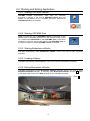
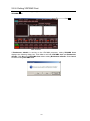
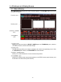
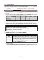
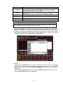
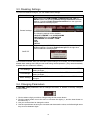
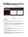

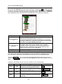
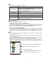
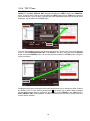
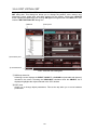
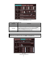
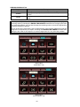
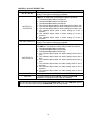
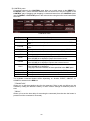


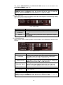

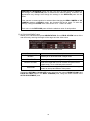
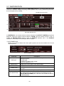
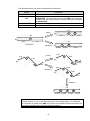
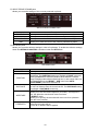


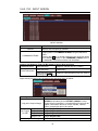
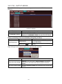
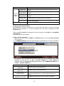
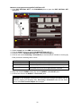
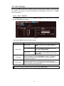
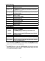
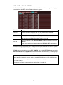
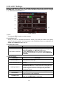
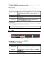
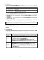

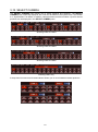
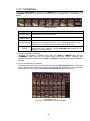
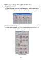
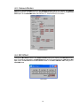


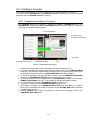
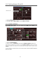
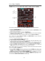
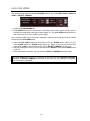
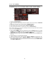
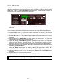
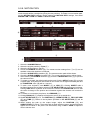


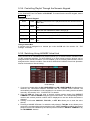
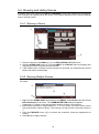

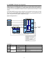
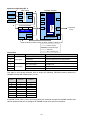
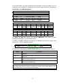
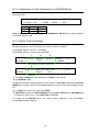
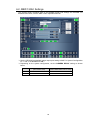
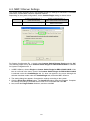
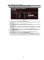
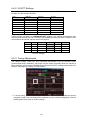
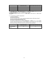


![VRCAM2取扱説明書[PDF:6.2MB]](http://vs1.manualzilla.com/store/data/006640273_2-96e1f4ae08153dcdd684b4b592e747f2-150x150.png)

![カタログPDFダウンロード[PDF:1.7MB]](http://vs1.manualzilla.com/store/data/006581727_2-bb010ce40f62d4b878607c76783fb901-150x150.png)
![VRCAM取扱説明書[PDF:2MB]](http://vs1.manualzilla.com/store/data/006716553_2-50d754f2a9ad4f3364dc2f0d5631e94e-150x150.png)
![SmartDirect取扱説明書[PDF:6.7MB]](http://vs1.manualzilla.com/store/data/006685208_2-aff58e80926c382fe1d043ce407b9aa2-150x150.png)
![MBP-12GUILE/12GUI取扱説明書[PDF:4.9MB]](http://vs1.manualzilla.com/store/data/006623918_2-b495e49e932502c0d2a50795758175dc-150x150.png)
![TCR Operation manual[PDF:2MB] - FOR](http://vs1.manualzilla.com/store/data/005966473_1-1d77f66abea204b380154f66141da9f3-150x150.png)


![ifCalibSTD取扱説明書[PDF:549.2KB]](http://vs1.manualzilla.com/store/data/006720962_2-f6f093a08a8e1adf50f2443be8c61b6f-150x150.png)
![VTW Software Operation manual[PDF:17.4MB] - FOR](http://vs1.manualzilla.com/store/data/005725901_1-df2c6d7f9199f46fcf33ffa12e63545b-150x150.png)
![MBP-100PD取扱説明書[PDF:1.1MB]](http://vs1.manualzilla.com/store/data/006610502_2-39f3623fc3ee971ebb71a027b67a85fa-150x150.png)