1
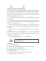
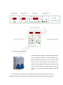
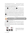
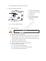
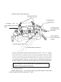
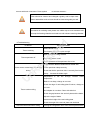
Cryostat Microtome RD-2298
U
nR
eg
is
te
re
d
Operation Manual
Helpful Suggestions:
l
The User manual should be considered part of the instrument. The user
should read this user manual carefully before first installation and before
operating the machine, and place the manual close to the machine for
reference.
l
The cryostat microtome must be operated by a trained operator. Before
operation, please carefully read the operating instructions, and familiarize
yourself with the steps and processes.
l
Unit must be shipped in the upright position. If the unit was shipped lying
down or stored lying down then it MUST stand upright for 36 hours before
use for all lubricating oils to enter the compressor
Do not put instrument under extreme temperatures or a high humidity
d
l
l
re
environment. Failure to follow this procedure will cause severe damage
Do not place instrument directly under sunshine or near air conditioning
l
te
vents
No other obstruction should be around the instrument within a 30cm
l
is
distance.
Check that your power outlet is well grounded. Ensure that power supply is
eg
stable, constant and adequate. Compressor requires a start-up current
between 45 and 50A.,Therefore, a professional electrical engineer should
nR
inspect the electrical circuit before installation in order to ensure the
smooth operation of the instrument. Requirements:
The instrument should be switched on 24 hours every day.
l
Blade is sharp, exercise extreme caution when changing it, remove when
U
l
cleaning the inside of the chamber
l
Do not place blade anywhere with the cutting edge facing upwards.
l
Before changing specimens, always lock the hand wheel and cover the
blade edge with the blade guard.
l
In case of malfunction, contact a qualified service technician. Don’t try to
solve problem by yourself.
1. Introduction
The Semi-automatic Cryostat Microtome, is a national regulated 1st class medical
device, is used for rapid freezing of pathological sections of human and animal body
tissue. It can be widely used for pathological diagnosis, analysis and research in
hospitals, medical colleges, and by legal medical experts and propagation institutes.
The cryostat microtome is the eighth generation of our cryostat. It utilizes advanced
horizontal feeding, The specimen chamber area is much larger than previous models.
The instrument consists of 4 major parts:
1.1 The computer control panel is on the upper part. This area displays the temperature
and the general working conditions of the instrument.
1.2 The center part is the constant low temperature chamber used to rapidly freeze the
tissue and to conduct the cutting.
1.3 Behind the chamber is the mechanical transmission and motor drive.
1.4 The lower part is the compressor unit , cooling condenser and evaporator.
2. Scope of Application
Pathological sectioning in order to study the histology of plant, animal or human tissue.
d
3. Technical Parameters
re
Section thickness range: 1-90µm Adjustable ,Increment:1µm,Increment:
±20%。
te
Trimming thickness range : 10 ~ 400µm Adjustable , Increment : 10µm ,
Increment:±20%。
Vertical stroke:
25mm
eg
Horizontal stroke:
20µm
is
Specimen retraction:
59mm
12°(X、Y、Z three directions)
Voltage:
220V±10%
nR
Specimen orientation:
Frequency:
50Hz
Power:
650W
U
Largest start-up current(5 second)
50A
Chamber temperature:
-10℃~-35℃ Adjustable
Freezing shelf temperature:
≤-50℃
Number of freezing station:
18
Peltier number:
2
Refrigerant:
R404a,300g±10g
Compressor oil:
0.6L
Dimensions:
Width(No hand wheel)
650mm
Width(With hand wheel)
790mm
Depth:
700mm
EMKARATE RL-22S, ICI
Height:
1150mm
Weight:
140kg
4. Working Condition and Pre-adjustment
4.1 The instrument is a movable floor type with 4 caster wheels. Two front wheels can
be up and down and are adjusted by turning knobs on the foot of the wheel. These front
wheels only function when the instrument needs to move. After removing the packaging
material, put the front wheels on the ground and move instrument to the working position
and secure it, then disable the front wheels.
4.2 The instrument should only be used after 4 hours of standing still to ensure proper
lubricant distribution.
4.3 Confirm the power supply is grounded (triple socket), then connect the instrument
d
with the main power socket, turn on the power switch at the back of the instrument, the
re
machine is now in operation mode.
4.4 Areas on both sides of the instrument should be clear to allow proper air flow to
te
the cooling unit. There should be a minimum of 300mm space to facilitate ventilation and
heat dispersion.
is
4.5 he instrument uses a single phase AC power supply, the voltage is
eg
110-115V±11V.
4.6 The instrument working ambient temperature is +5℃~+28℃. If the temperature
is above 26℃, air conditioning must be installed; otherwise the life time of the cooling
nR
compressor will be shortened.
U
4.7 Environment relative humidity should be no more than 80%.
High temperature or humidity will influence freezing effect and
shorten compressor life.
5. Installation
5.1 Freezing chamber assembly
l
Place left and right shelf in the freezing chamber outside of microtome;
l
Place the waste tray in the freezing chamber;
l
Install blade holder on the microtome base and lock it.
l
Insert blade to precool;
l
Place all tools needed for specimen preparation in the chamber;
l
Close glass window to enclose chamber.
5.2 Connect Power
6. Operation
6.1 General overview
Check your power socket is well grounded. Ensure that power supply is
stable, constant and adequate. Compressor requires a start-up current
between 45 and 50A.,Therefore, a professional electrical engineer must
inspect the electric circuit before installation to ensure the smooth operation
te
re
d
of the instrument.
eg
Main
Right side
Control Panel
U
nR
Left side
Control Panel
is
Main Control Panel
Glass Window
Moving Handle
Handwheel
Waste Liquid
bottle
d
re
te
is
eg
nR
U
6.2 Turning the Instrument On
Confirm the power supply is grounded (triple socket),
then use attached power line to connect the instrument
with the main power socket, turn on the power switch
on the right of the instrument, the machine is in
operation mode. Main power is shown as Fig 5 on the
right of the instrument. The switch must be in the top
position for “on” and in the bottom position for switching
Fig 5
“off”.
Turn on the power switch on the right side of the instrument, the machine is now in
operation mode, the sectioning arm automatic reset. LED on the left side control panel
should now display “06” µm , that indicates default section thickness is “06” µm and
present work mode is “sectioning” mode. LED on the right side control panel
displays”----“ to waiting for system reset. After reset buzzer, LED on the right control panel
displays “0” to show total sectioning number.
6.3 Function of main control panel(Please refer to Fig 2)
Main control panel is separated into 4 parts. From left to right in sequential order are
Freezing shelf area, Freezing chamber area, Time setting area and Special function area.
6.4 Peltier element
Under a normal state, the peltier element is off. LED
button ,
d
shows freezing shelf temperature. Press
indicator light comes on and peltier element begins to
re
work to cool down the freezing stations. LED displays
“L15”, which means peltier element will work 15 minutes.
Fig 6 Peltier element
te
The countdown of the remaining cooling time is now
is
permanently displayed.
eg
The Peltier element turns off automatically after 10 minutes.
Once the remaining cooling time displayed is 4 minutes, the figure 4 is followed
by a point (“ 4. “). At this stage the Peltier element may be deactivated
‘. pressing
nR
by pressing peltier button again. Once deactivated, the display indication returns to ‘PE
the button during the peltier element working process will stop
U
peltier freezing immediately.
6.5 Temperature setting
Compressor will start to work after turning on power switch allowing the freezing
chamber to cool down. (depending on the interval betwen turning off and on, if switched
within 3 minutes, the instrument requires 3 minutes for compressor to start again).
Freezing chamber temperature is shown and set by temperature set area as Fig 6.
Normally LED displays temperature of sensor in the freezing chamber.
Freezing chamber temperature displayi and setting:
System default temperature is -22℃. When the
instrument is under idle state, press “
”to increase
temperature; press “
”to decrease temperature.
At present, the unit’s LED is flashing to display set
value. When set to desired temperature, wait about
15 seconds, the instrument go back to normal state.
Fig 6 Freezing chamber temperature User can adjust temperature within the adjustable
range.
Displays buttons on the panel stand for:
6.6 Time setting
SUN: Sunday
MON: Monday
TUE: Tuesday
WED: Wednesday
THU: Thursday
FRI: Friday
d
SAT: Saturday
PM:Afternoon
re
AM: Morning
W-DAY: Working day H: Hour
te
6.6.1 Present time setting
M:Minite
is
Fig 7 Time setting area
eg
After turning on system default time,if is not correct, then reset it. When system is
under idle state, press “D” button to adjust day, light will flash correspondingly. Press
“H” to adjust hour, the left two digit place of LED will flash; Press “M” to adjust minute,
nR
the right two digit place of LED will flash. About 10 seconds after setting, the
instrument will return normal state
U
Note: if setting time is over 10 seconds between two operations, system will
automatically return to normal state. Below setting is the same.
6.6.2.Programming working time
When under idle state ,Press “
“ button once,
symbol lights and is ready
to enter programming mode. Left side LED displays “F1.1”;Front F1 stands for first
mode; the other 1 stands for switch on mode. The lights from Mon to Fri all light up
concurrently.
That means the instrument is on the working temperature From
Monday to Friday; instrument goes into stand by mode on the other time. Under this
condition, if “D” button is pressed, it does not function. Hour button ”H” and minute
button “M” are used to adjust hour and minute respectively. When in programming
mode, LED right digit will flash; Then press “
“ again to go into “switch off” mode.
Left side LED displays “F1.0”;F1 this is the same function as above F1; 0 stands for
switch off mode. Switch off programming method is same as above. 10 seconds after
finishing programming, the instrument returns working state.
6.6.3 Programming the working time for each day
Press “
“ button three times continuously,
indicator lights up and unit
goes into time programming. Left side LED displays “F2-1”; first 2 stands for second
time programming mode, 1 at the end stands for switch on mode. User may program
different time for every day within one week. If sigle light is on among Monday to
Sunday, user may program that day working time. Press “ D” to change among days.
Hour button ”H” and minute button “M” are to adjust hour and minute respectively.
d
When under programming, LED flash with right digit; user then needs to
“ again to go into switch off mode. Left side LED displays “F2-0”;front 2 same
re
“
press
function as above; 0 stands for switch off mode. Switch off programming method is
te
same as above. 10 seconds after finish programming, the instrument returns working
is
state.
eg
Note: If Sunday is out of work, program switch on and off time as same time.
6.6.4 Programming the defrost cycle
” button that is in time control area. Defrost indicator light is on and enter
nR
Press “
defrost programming. Indicator lights of week on the top line go out currently. It
represents that program same defrost time every day. ‘W’ button is not available. Hour
U
button ”H” and minute button “M” are to adjust hour and minute respectively.
Programming time is defrost beginning time. About 10 seconds after programming,
system return idle state.
6.7 Function buttons
There are fast defrost, stand by, UV
sterilization lamp and illumination
buttons in function area as shown in
Fig 8.
Fig 8
6.7.1 Locking key
When user press locking key, time setting area is locked and could not be
changed unless press it again.
6.7.2
Fast defrost button. Under normal freezing state, it is in unlit. Press “
”
to activate fast defrost function and indicator light is on, system goes into fast
defrost mode. Press button again to cancel fast defrost, indicator light goes out
simultaneously. Unit should then defrost withing a 6 minute time period.
If system automatically enter fast defrost mode,
button lights up too.
Press it again to stop fast defrost and indicator light goes out.
d
6.7.3 UV sterilize lamp
re
is UV sterilization button. Press it to make UV lamp active; press once more to
stop it. Indicator light is on or off correspondingly. It is better to start to sterilize with
te
UV lamp under stand by situation.
is
Note:UV radiation is harmful for human body. When doing UV sterilize,
eg
do not forget to close glass window and keep hands away from chamber.
nR
Note:Before doing UV sterilization, please remove all specimens and
clean chamber first.
U
6.7.4 Stand by
is stand by button. Under normal state, it is dark. Press it one time, system
goes into stand by mode. Press it again to return normal working state.
Indicator light is on or off correspondingly.
Under stand by state, freezing
chamber temperature is maintained between -4℃ ~ -9℃, to conserve
electricity.
If system automatically enter stand by mode,
button lights up too.
Press it again to stop stand by function and indicator light goes out.
6.7.5 Illumination
Illumination button. It is dual function button. First press lamp is on; second
press lamp is off.
6.8 Use of the liquid waste container
Use the wasted liquid barrel to collect defrosted liquid, tissue thawing solution,
flushing liquid and waste objects. In order to prevent human and environmental
hazard from the waste, put 200ml 10% formalin or other sterile solution into the barrel
in advance. The disposal of the waste shall follow all the related regulations of the
d
hospital.
6.9 Left side control panel(Refer to Fig 3)
te
6.9.1 Specimen forward and backward feed
re
Note:Use the right and effective method to treat the waste.
is
Specimen forward and backward feed is for user fast move specimen position. If
user press
button, specimen
eg
press
button, specimen goes to home position in normal speed;
goes forward in normal speed. Press
position in fast
button moves to opposite direction in fast speed.
nR
speed; press
button, specimen moves to home
Press
button to
U
cancel moving command.
6.9.2 Section/Trim thickness selection
Fig 9 is shows section/trim control. Above LED displays
the thickness value of section/trim.
If “SECT” lights up, LED displays section thickness,
otherwise, is trim thickness.
Press “T/S” button per
change from section to trim one time, or conversely.
Fig 9 Section/Trim selection
and display
Section thickness range: 1-90µm (default value is 6µm)
to
1~20µm,in 1µm steps;
20~40µm,in 2µm steps;
20~60µm,in 5µm steps;
Trim thickness range:10~400µm(default value is 30µm)
10~50µm,in 5µm steps;
50~100µm,in 10µmsteps;
100~400µm,in 50µmsteps;
6.9.3 Thickness selection
Under current working mode, adjust “
“ or “
“ to select section or trim
d
thickness.
re
6.9.4 Section
Turn the hand wheel one rotation, the system will cut the one piece of section one
te
time, and the thickness is the preset thickness.
is
Note:When adjusting
specimen
quickpanel(Fig.
fro and back
movements, the
6.8 Right
side control
4)
eg
hand wheel mustRight
lock side
at thecontrol
right position.
Refer toofFig.
18. and vacuum extractor
panel consists
counter
two control sections.
nR
6.10 Right side control panel(Refer to Fig 3)
6.10.1 Counter
U
As left Fig 10, above LED displays number of total pieces and
thickness. When Σn lights up, total pieces is shown in LED; on
the contrast, Σμm lights up, total thickness is shown. Press “M”
button to change from total pieces to total thickness one time,
or conversely. Press “C” to clear all the numbers to 0.
Fig 10
6.10.2 Use of vacuum extractor
Vacuum extractor is designed for cleaning tissue
scrap. Press
button on the right control panel to enable extractor motor. Indicator
light on the upper corner of symbol is on. Move speed controller on the left side to adjust
motor speed to choose suitable air volume. Press again to disable it; indicator light is off
simultaneously.
7. Mechanical introduction
te
re
d
7.1 Freezing shelf
eg
is
Hammer
nR
Peltier station
Freezing shelf
Station
Freezing disc
Specimen
Fig 12 Freezing shelf description
Freezing shelf with 20 stations is located to the left of freezing chamber. The lowest
U
temperature of freezing shelf may arrive to -40℃。 Two project stations in the front of
freezing shelf are peltier stations that the lowest temperature may arrive to -60℃.
Procedure of preparing specimen is as follows:
l
Cut specimen into proper size;
l
Put specimen onto freezing disc between layers of tissue freezing medium;
l
Put freezing disc into station on the freezing shelf;
l
Use hammer plat the specimen surface;
l
The specimen is frozen by low temperature quickly;
l
Move away hammer after it is frozen ;
l
Insert freezing disc with specimen into hole of clamp on the microtome, then
tighten locking handle;
l
Adjust angle of knife holder and blade;
l
Rotate handwheel to cut specimen into sections.
7.2 Microtome component introduction
1. Freezing disc locking handle
2. Orientation adjustment handle
1
3. Orientation lever
2
3
4. Extractor hole
5. Knife holder locking block
6
6. Specimen hole (Inserted
4
freezing disc).
Microtome parts introduction
is
7.3 Inserting freezing disc
te
Fig 13
re
d
5
eg
Note: Before inserting freezing disc, please lock handwheel well
Release freezing disc locking handle;
l
Insert the shaft of the freezing disc in the location hole of the specimen
nR
l
clamp. Make sure that the shaft of the freezing disc is fully inserted. The
U
entire rear surface of the prism should contact well with the specimen clamp,
there should be no gap between them;
l
Lock freezing disc locking handle and fix it,
l
Observe cutting angle, if necessary, adjust orientation;
l
Procedure for adjusting orientation:
n
Loosen orientation adjustable handle;
n
Adjust orientation lever to choose best cutting angle;
n
Relock orientation adjustable handle.
7.4 Blade holder position adjustment
Fastening slide knob
①Clamping lever
for locking blade
②Turning lever to
move blade holder
left to right
③Turn rotator to
adjust cutting angle
of blade
eg
is
te
re
d
④ Clamping lever for
moving blade holder fro and
back
nR
⑤Anti rolling plate height knob
Fig 14 Blade holder introduction
U
Release(anti clockwise)blade holder lock handle on the left(④Fig .13)
,manually
move the holder fro and back and lock it at the desired position. When the holder
moves to the terminal point the whole blade holder can be taken out and put it back
by reversing procedure. Release(counter clockwise)blade holder lock handle on
the right, manually move the holder left and right and lock it at the desired position.
Note: Remember to lock the blade holder to right position when doing
forward or backward specimen adjustment.
7.5 Change the blade
Release clamping lever ①on the upper right to open blade clearance; insert blade
from left to right; then lock the clamp lever(Fig 13)
。
Note:Blade is sharp, beware when you change it.
7.6 Adjust the angle of the blade
Loosen the lowest adjustment handle③ on the right side of blade holder. Refer to
reference scale to turn rotator in order to choose best cutting angle of blade. Retighten
the adjustable handle.
7.7 Adjust the anti rolling plate
Parallel
Blade
⑥
Knob
for
clamping anti rolling
plate
eg
is
te
re
d
Anti rolling plate
Anti rolling plate height knob
⑦Using hexagonal wrench to blade
and slide make parallel
nR
⑧Handle for replace scrap collector
U
Fig 15 Making parallel between edge of blade and slide
The anti roll plate is made of Plexiglas.
Adjustment includes:
1、Make the edge of the anti rolling plate parallel to the edge of the blade.(Fig 15)
l
Insert blade and lock the clamping lever(①)
l
Lock two knobs⑥.
l
Use hexagonal wrench to make blade and anti rolling plate parallel
l
Fasten hexagonal screw⑦
l
Turn height turning knob⑤ to adjust height of anti rolling plate
Note: Please use ⑧Handle to replace scrap collector , do not touch
other knobs unless you want to adjust parallel.
2. Adjust the anti rolling plate angle with the blade.(Fig 16)
Tissue
Adjustable angle
10
°
Angle of cutting blade edge
is
te
30°
re
d
Anti rolling plate
eg
Fig 16
nR
The angle shall be no more than 10°
。
U
3、Make the edge of plate and edge of blade flush(Fig 17)
Edge of plate and blade
meeting flush
Anti rolling plate
height turning knob
Fig17 Making flush between edge of blade and anti rolling plate
1.
The upper part of the anti-roll plate should not contact the
tissue specimen.
2. When the quality of the tissue section is not good, check the
edge of the blade, check any segment of tissue on the plate,
any fat or other foreign matter.
3. Avoid touching the front of the plate, because high
temperature will adhere the tissue section to plate.
d
7.8 Section reference
re
1、When using the cryostat microtome, controling the blade speed and correctly
adjusting the anti-roll plate are important factors in cutting high quality sections.
te
The proper speed of the blade can only be acquired by practice and experience,
along with skillful control of the hand wheel. The proper adjustment of the anti-roll
eg
require careful adjustment.
is
plate requires even more practice. Sometimes they interfere with each other; and
2、When freezing living tissue, the water within the tissue will condense into ice, the
tissue will become hard. The hardness changes with the temperature, the lower
nR
temperature the harder the tissue becomes. Different tissue reacts differently
under different temperatures, achieving high quality sections, can only be
obtained through practice. cutting temperatures of the specimen tissue without fat
U
and formalin, should be between -13℃~-23℃ .
3. For high quality sectioning, pay attention to the following:
(1)Proper selection of working temperature in the chamber
(2)Correct slicing operation and hand wheel speed
(3)Fine adjustment of the anti-rolling plate
(4)Sharp blade edge, correct blade angle
4. Frozen sections are just the opposite of paraffin slicing,the frozen sections should
not be cut in wide sections, better to cut less wide sections so that the line of
contact is shorter.
7.9 Hand wheel lock
To achieve operator convenience and
safety, we designed a handwheel locking
function for the cryostat. Lock handwheel
at the top position not in use to avoid
unnecessary harm. f The locking position
“3-8 o;clock” are at the top while gearing
handle is facing to operator as showing in
Locking spanner
the Fig 18.
re
d
Rotary lever
is
te
Fig 18 Hand wheel locker
7.10 Installing and Changing the Section Extraction
Please take care of this precision instrument carefully. It needs daily cleaning
U
nR
eg
and regular maintenance to achieve a long life for the instrument.
2
3
4
1
Fig 19
Extractor assembly
1.
2.
3.
4.
Suction nozzle
Hose
Filter
Extractor install hole
on the instrument
Connect assemblies of extractor according to Fig 19. Assembly ④ in Fig 19 is
extractor install hole on the instrument. Screw assembly ③ into assembly ④ to
connect with main instrument. Press symbol
to activate extractor.。
Filter should be cleaned and changed regularly and be kept clear.
Other assemblies such as hose should be cleaned regularly as well.
If extractor is not being used, please use rubber cap to cover extractor hole
to keep the freezing chamber enclosed to avoid moisture entering chamber.
d
8 Troubleshooting
Causes/Remedies
re
Problems
Select thinner tissue,
Tissue cracking
te
The freezing time is not quick enough
Tissue specimen off
is
Apply more embedding material
The cutting tissue is soft
eg
The temperature of the specimen disc is low
Ensure that the blade is fastened and seated well.
nR
Tissue moves across blade, but without
U
slicing
Fix the specimen clamp securely
Check that the the specimen disc is securely fixed on the
clamp- Increase the blade angle
Temperature
is
not
low
enough,
chooser
lower
temperature.
Blade is not sharp, change to new one.
Check the edge of anti-rolling plate if broken, change to
new one .
Tissue section rolling
Anti-rollplate is not clean. Clean with alchohol.
Check the gap between the anti-roll plate and the blade,
adjust the angle of blade
Increase the height of the anti-rolling plate
Check the angle of the anti-roll plate and the blade
Tissue becomes soft when cutting
Prolong the refrigeration time of the anti-roll plate and the
blade
Tissue section stick to the anti-rolling
plate
Use short hair brush to clean the anti-roll plate
Prolong the refrigeration time
Clean the blade with camel hair brush
Tissue section overlapping
The clearance angle between the blade and the anti-roll
plate is too narrow
Edge of the blade has a defect,
Vertical crack of tissue section
Foreign matter on the blade
Adjust the clearance angle of anti-roll plate and the blade
Tissue section narrows
evenly
d
Too low temperature of the tissue, too long time freezing,
Tissue section broken
re
Blade is not sharp, change to new one.
Blade sticking with some impurity, clean and brush
te
Unfixed blade
The angle of the blade is too big or too small
Vibration when slicing
is
Specimen did not arrive at slicing temperature, please
continue to freeze it.
eg
Specimen clamp is unfixed
The specimen disc is not fixed well
nR
Cutting speed is too fast
U
Uneven thickness of the tissue section
Temperature is not proper
Microtome did not dry completely
Dull blade
Angle is too small
The specimen disc is not fixed
Microtome inside is not dry completely- allow to dry
Microtome itself damaged. Please contact with technical
service.
Rotate handwheel, but no feeding
Defective Photoelectric sensor.
Defective stepper motor
Defective stepper motor driver
Check the power line, Reconfirm power to line.
No display after power on
Fuse blown, Change fuse.
Defective Stepper motor.
Can’t reset after turning on instrument
Defective Stepper motor driver.
Lead screw or nut is broken,
Upper limitation Photoelectric sensor is defective
Check the solid state relay and change if necessary.
Compressor is damaged
te
Compressor doesn’t operate after
turning on instrument more than 4
minutes
re
No time and temperature display
d
Connection cable between main board and display board
has problem
Display board is defective
Defective Solenoid valve.
No defrost
Lamp does not come on
eg
is
Defective Solenoid valve power supply,
Lamp is broken,
nR
Lamp wire has problem,
Defective Temperature sensor.
U
Chamber temperature stays same.
Freezing shelf temperature stays same.
Defective Temperature sensor.
Lack of refrigerant, please call to service to add some
T404A. and check for leaks
chamber temperature can’t reach to
Room temperature is too high. keep more ventilation, or
the programming temperature (under
install air conditioning to regulate chamber temperature
running condition)
at 25℃.
Bad ventilation on both sides of the instrument. Move
things away from both sides, keep good ventilation.
Fan working but compressor not
Defective Compressor.
Freezing shelf temperature is unstable
Water in the cooling distribution system, ice blockage. If
the outlet of the compressor is sometimes hot and some
times cold, indicates water causing ice blockage. Call to
manufacturer to vacuume and recharge system
eg
is
te
re
d
Compressor is working without freezing
Capillary tube (pressure relief valve) blocked, call
service.
Leakage of the refrigerant, call service.
nR
9. Safety,Maintenance and importance
9.1 Make sure that hand wheel is in the lock position when the instrument is not in
9.2 Change the broken lamp accordingly(110V 12W)
,pay attention to safety when
U
use.
doing the exchange.
9.3 Change the broken lamp accordingly(110V 8W)
,pay attention to safety when
doing the exchange.
9.4 The elements of the electric system, such as control panel, electric control box,
require expert maintenance.
9.5 The cooling system mainly consists of compressor, condenser, filter, and
evaporator. The condenser (with fan) may accumulate dust after long usage; this can
affect the cooling function. It is necessary to open the side ventilation board and use
brush to clean the dust on the projecting vanes of condenser, or use high pressure air
to blow it clean.
9.6 Frequently clean the constant temperature chamber, to keep it clean. Remove
blade before cleaning
9.7 There are 5 fuse seats at the rear of the instrument, from left to right models and
functions are as following:
F2
F3
F4
F5
5A
1A
1A
3A
3A
power
UV lamp
lamp
extractor
peltier
re
d
F1
is
10. Clean and maintenance
te
If broken, please change them according to above model.
eg
These machines are precision instruments. Pay attention to
cleanliness, maintenance and repair work. Regularly clean and
disinfect.
nR
10.1Daily cleaning work for freezing chamber
Conduct the following steps before cleaning each time:
l Take out all specimens from freezing chamber;
U
l Turn up the specimen grip to the top and lock the hand wheel.
l Remove the blade from the blade holder and put it back to the blade box;
l Activate extractor to clean away scraps;
l
Empty waste tray;
l
Use alcohol or common disinfectants based on alcohol to clean baffle and brush
shelf;
l
Collect waste cleaning liquid into wasted liquid barrel, then dispose it.
Do not use organic solvents or any other aggressive substances to
clean and sterilize the chamber! Only use the cleaning agents specified
in this manual such as alcohol or common disinfectants based on alcohol.
Please
do manual
defrost
before
cleaning if chamber full of frost.
10.2
Instruments
and
external
surface:
If necessary, the external painted surface can be cleaned with light-duty
commercial housework cleaner. Use wet cloth rub it until dry. Do not apply xylene
or alcoholic liquid (eg: glass cleaner )
10.3 Spray disinfection
The cryostat has to be disinfected after each daily use and cleaning. Steps are as
following:
Cool down freezing chamber temperature to -20℃;
l
Spray disinfectant after temperature decrease enough;
l
Wait for 15 minutes;
l
Wipe chamber off with tissue paper or dry cloth 。
l
Reprogram temperature according to slicing requirement after disinfection.
10.4 Blade holder cleaning
te
re
d
l
is
If blade holder sticks contains impurities and is sticking, dismount and clean it as
l
eg
below:
Turn the adjustable handles in the lateral of rotator and draw it out from
sideward.
Push the knife clamp back which have knife clip and shift it out from the rotator.
l
Turn the eccentric rod handle in the lateral of the knife clap and draw it out from
nR
l
sideward.
l
Clean all the assemblies of blade holder;
U
l
Dry off all the assemblies and apply a drop of low temperature lubricating oil on
them;
l
Reassembly blade holder and put into freezing chamber.
Before putting the blade holder back make sure all the assemblies are
dry.
10.5 Lubrication
Do low temperature oil lubrication for the following parts weekly. (1~2
drop is well enough).
10.6 Removal of the microtome
After long periods of not being used, inside of microtome needs lubrication, please
remove microtome out of freezing chamber. Steps are as following:
l
Remove glass window;
l
Take all the accessories out chamber such as brush shelf, left storage shelf, right
storage shelf, freezing disc, waste tray, blade holder.
l
Use Allen key to loosen screw;
l
Take off plug of step motor;
l
Remove temperature sensor;
l
Slightly lift the microtome and pull it to the left to disengage the plastic coupling
(5) connecting the axes.
Take the microtome out of the freezing chamber;
l
Loosen the screws on both sides of cover
l
Take away cover and dry off microtome;
l
Yon may place microtome into oven at 40℃-50℃ temperature about 4 hour to
te
re
d
l
is
dry it. But you must apply low temperature lubrication oil to cross roller bearings.
eg
Please pay attention to below notice when user put microtome back to freezing
chamber carrying on opposite procedure:
n
Ensure that the clamp is in the lowest position, and then place the microtome
n
nR
slightly into the left side of freezing chamber;
Apply a drop of low temperature lubrication oil on the plastic coupling so that it
may connect well with shaft;
Use right hand to put handle of handwheel at the lowest position, and universal
U
n
clamp at the lowest position too;
n
Use left hand push microtome to right side, turn the handwheel up and down to
ensure proper alignment of plastic coupling and shaft.
Do not directly use heater to dry off freezing chamber. This can cause damage to
the cooling system!