1
TMBSCOM.DLL
Termi-BUS SIO Control Library
For Win32 PC Based Controller
FunctionManual
Document No.
Ver. 2.00
DEE-00054F
14th / Feb. / 2003
Dyadic Systems Co., Ltd.
DEE-00054E-1
Index
1. Termi-BUS for PC based controller.......................................................................................................................4
2. Termi-BUS compatible servo system and TMBSCOM.DLL ................................................................................4
2.1. Summary of Termi-BUS SIO..........................................................................................................................5
2.2. Summary of TMBSCOM.DLL .......................................................................................................................5
3. Features of TMBSCOM.DLL ................................................................................................................................6
3.1. Call out from VisualC/C++ Application .........................................................................................................6
3.2. Call out from VisualBasic application ............................................................................................................6
3.3. ISaGRAF use C language function library .....................................................................................................6
4. TMBSCOM.DLL Function references ..................................................................................................................7
4.1. Each function common constant for previous definition ................................................................................7
4.2. Communication establishment procedure and communication status check function ....................................7
4.2.1.
Functions of init_tmbs_config ...........................................................................................................7
4.2.2. Fuunction of init tmbs ..............................................................................................................................9
4.2.3. Function close_tmbs..............................................................................................................................9
4.2.4. Function init_sio_tbus..............................................................................................................................9
4.2.5. Function init_sio ......................................................................................................................................9
4.2.6. Function get_tmbs_state...........................................................................................................................9
4.2.7. Function get_current_baud.....................................................................................................................10
4.2.8. Function get_sio_error ...........................................................................................................................10
4.2.9. Actual procedures of communication establishment and notes .............................................................11
4.3. Motor movement order function and movement completion confirmation function....................................11
4.3.1. Function of move point (position number specification indirect PTP movement order).......................11
4.3.2. Funnction “move_abs” (Absolute positioning order PTP movement order) .........................................11
4.3.3. FUNCTION OF move_inc (incremental movement distance specify PTP movement order) ...............12
4.3.4. Fuunction “move_org” (Homing movement order) ...............................................................................12
4.3.5. Function “move_rotate” (unlimited revolution movement order)..........................................................14
4.3.8. Function “move_jog” (JOG movement order) .......................................................................................15
4.3.9. Function ”check_pfin” (positioning completed status acquirement) .....................................................15
4.3.10. Funnction “check_status (Servo system internal status polling)..........................................................15
4.3.11. Function “follow_position” (Current position follow up/Immediate stop)..........................................16
4.3.12. Notes of axes movement order.............................................................................................................16
4.4. Servo system status change function.............................................................................................................17
4.4.1. Function of “write_position” (Current position direct set) ....................................................................17
4.4.2. Function of “set_son” (Servo ON order)................................................................................................17
4.4.3. Function of “set_soff” (Servo OFF order) .............................................................................................17
4.4.4. Function of ”reset_alarm” (Servo amplifier alarm reset) .......................................................................17
4.5. Motor movement parameter change functions..............................................................................................18
4.5.1. Function of “write_velocity” (speed/acceleration order set)...............................................................18
4.5.2. Function of “select_svparm” (servo gain parameter selection)..............................................................18
4.5.3. Function of “write_trqlim” (Electrical current limit value set) ...........................................................18
4.5.4. Function of “write_inpos” (positioning completion detection width set) ..............................................19
4.5.5. Function of “write_fzone” (zone output +side border value set) ...........................................................19
4.5.6. Function of “write_rzone” (zone output – side border value set) ..........................................................19
4.6. Servo system internal status check function .................................................................................................19
4.6.1. Function of “check_run” (servo system RUUN status acquirement).....................................................19
4.6.2. Function of “check_son” (servo ON/OFF status acquirement)..............................................................19
4.6.3. Function of “check_alrm” (alarm status acquirement)...........................................................................20
4.6.4. Function of “check_org” (homing completion status acquirement).......................................................20
4.6.5. Function of “get_status” (servo system internal status acquirement) ....................................................20
4.7. Virtual memory space access function in Servo amplifier/motor .................................................................21
4.7.1. Random access read out function from virtual memory space...............................................................21
4.7.2. Random access read out function from virtual memory space...............................................................22
4.7.3. Servo system movement parameter write function ................................................................................22
4.7.4. Servo system movement parameter read out function ...........................................................................22
4.7.5. PTP movement order data write function...............................................................................................23
4.7.6. PTP movement order data read out function..........................................................................................23
4.7.7. Servo system movement parameter load function..................................................................................24
DEE-00054E-2
4.7.8. Servo system movement parameter save function .................................................................................24
4.7.9. PTP order data save function .................................................................................................................24
4.7.10. Memory initialization function of servo amplifier ...............................................................................24
4.8. Notes of COMPACK structure body and virtual memory space ..................................................................25
This document describes based on TMBSCOM.DLL version 3.00 or later.
DEE-00054E-3
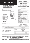
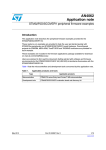
1. Termi-BUS for PC based controller
Because actuators in mechanical systems have own unique interfaces depending on their types, design of
system and control become very complicated and the result is that users limit the use of actuators types,
therefore this becomes the biggest factor of the obstacle to use best actuator for the application.
Termi-BUS is the interface between system controller and servo amplifier to make overall control with various
actuators. It will allow various servo actuators to be controlled with same digital information, therefore now it
is possible to choose the best actuators without over design and over specification.
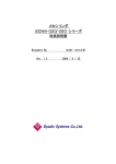
PC based controller establishing FA controller on personal computer is one of best way to build flexible
controller in short time by using commercial hardware and software. Termi-BUS SIO will give PC based
controllers effective servo actuator functions.
Termi-BUS SIO control library can build PC based controller easily with the core of Termi-BUS SIO
compatible servo system and software PLC. Because such system controllers with this need only basic
hardware of PC for the execution condition, hardware cost will be minimized, and also such system can utilize
commercial hardware and software and have high level of expansion ability and flexibility due to the fact that
special real time operation systems for task change time reduction are not needed, and special real time
expansion for standard operating systems is not needed.
I/O ƒ‚ƒWƒ…
module[ƒ‹
I/O
I/Oƒ‚ƒWƒ…
module[ƒ‹
I/O
Termi-BUS
&
ISaGRAF
ƒŠƒ‚
[ƒg I/O
Remote
I/O
( DeviceNet, InterBus-S, MELSEC-NET etc.)
(Device Net, InterBUS-S, MELSEC-NET, etc.)
Termi-BUS Win32
PC Based Controller
Termi-BUS SIO
B
U
V
W
P
N
R
T
BAA
B Series
ƒT
[ƒ{ƒVƒXƒeƒ€
Servo
system
R Series
ƒT
[ƒ{ƒVƒXƒeƒ€
Servo
system
RC Series
ƒAƒ“ƒv“à‘
Built-in
ƒT [ƒ{ƒ‚ [ƒ^
amplifier
2. Termi-BUS compatible servo system and TMBSCOM.DLL
Termi-BUS compatible servo amplifier has drastically small traffic in interface between upper controller due
to built-in PTP (Position To Position) motion control creation function compared with traditional interface that
is always sending position increment order. Therefore Termi-BUS compatible system doesn’t need dedicated
designed hardware to interface control of servo actuator, and hardware cost will be smaller. There are 2 types
of upper controller interfaces in Termi-BUS compatible servo system, Termi-BUS PIO structured with
parallel I/O (DC24V) and Termi-BUS SIO with serial communication. TMBSCOM.DLL is a library software
to control these servo systems through Termi-BUS SIO from application program on PC with 32 bit Windows,
it will allow PC programming very easy due to its flexible function of Termi-BUS SIO.
DEE-00054E-4
2.1. Summary of Termi-BUS SIO
Termi-BUS SIO has flexible and abundant command system and effective protocol as servo actuator
control dedicated interface, and it will allow system to order more flexible and higher functions compared
with axes controller orders through remote I/O and PLC I/O modules. Termi-BUS SIO is self-adjustable
synchronizing type of serial BUS interface based on EIA RS485, it can be connected directly to standard
COM (serial) port of PC through ADP-1 of RS232→RS485 converter.
Termi-BUS SIO connects dizzy chain with servo amplifiers through modular cables, and one COM port can
control up to 16 axes of Termi-BUS compatible servo systems. Termi-BUS SIO interface is integrated as
standard function in Termi-BUS compatible servo system.
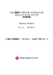
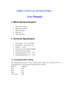
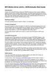
2.2. Summary of TMBSCOM.DLL
TMBSCOM.DLL is a dynamic link library to utilize effectively servo control functions generated by
Termi-BUS SIO on 32 bit Windows application, and there are provisions of functions corresponding to
control function unit such as positioning, positioning completion confirmation, etc., therefore programmers
don’t need to consider detailed control of communication protocol and hardware source by using those
functions.
TMBSCOM.DLL can be opened freely from regular Windows application made by VisualC/C++ or
VisualBasic, etc. same way as regular dynamic link library. If as long as software PLC is operated on 32 bit
Windows, it can be called out from user definition C language function, etc., and high level servo control
functions can be utilized easily on PLC program.
Win32 PC-Based Controller with Termi-BUS SIO
SoftwarePLC
Run-Time
Executive
VisualBasic
Application
VisualC/C++
Application
User Defined
C-Function
TMBSCOM.DLL
Termi-BUS SIO Control Library
Win32 API
Software
Windows Operating System
PC Hardware Resource
Serial Port
ADP-1
Termi-BUS SIO
Series B
Servo
Amplifier
Series R
Servo
Amplifier
Series RC
Servo
Motor
Hardware
Series SC
Inteligent
Cylinder
DEE-00054E-5
3. Features of TMBSCOM.DLL
By using functions of TMBSCOM.DLL, it is possible to use all functions of Termi-BUS SIO. These
functions are to execute all communication procedure automatically such as confirmation of
command-response from transmission of command to receipt of response and error recovery, therefore it is not
necessary for users to consider communication procedure details of Termi-BUS SIO.
Once Termi-BUS SIO communication is established by communication establishment procedure execution
function, Communication status parameter indicating communication control faults and all axes servo system
movement status monitor parameter at communication establishment will be created in dynamic link library.
These status parameter will be updated every time when Termi-BUS SIO is executed, users can read out those
by rececived contents of status parameters.
3.1. Call out from VisualC/C++ Application
TMBSCOM.DLL is coming with TBUSSIO.H declared header file of function prototype and
TMBSCOM.LIB file in order to linkage application of each function entry. Users will use these files to call
any functions of TMSCOM.DLL freely from visualC/C++ application. TBUSSIO.H will declare all
WINAPI for those functions, therefore users can call these same way as call-out regulation of WinewAPI
functions. Also TBUSSIO.H has designated returned value from each function, constant to pick bit
information from used parameter as flag, users can these in own program freely.
3.2. Call out from VisualBasic application
TMBSCOM.DLL will be provided with files of TBUSSIO.BAS declared as public procedure function.
Users can call any functions of TMBSCOM.DLL freely from any VisualBasic application by inserting
these files as standard module into project. TMBSCOM.DLL is included returned value from each function,
pubic definite parameter to choose bit information from used parameter as flag, users can use those in their
program freely.
3.3. ISaGRAF use C language function library
ISaGRAF user C language function library used TMBSCOM.DLL is a software PLC tool to use
Termi-BUS compatible servo system effectively. This library is provided as ISaUSP.DLL of object format
of user C language function for ISaGRAF, source codes and function templates including technical memo
will be provided as archive files for librarian, users don’t need to make R&D work and can use these
functions as any of IEC-1131-3 PLC programming language (IL, ST, LD, FBD). If user has developed own
C language function, these can be integrated and rebuilt easily because ISaGRAF has source code set
needed to rebuild C language function library.
TMBSCOM.DLL is based on the use of ADP-1 with RS-232C/RS-485 converter, therefore please note that
the system doesn’t operate well in case of use of other converter than ADP-1.
DEE-00054E-6
4. TMBSCOM.DLL Function references
4.1. Each function common constant for previous definition
Following constant used in TMBSCOM.DLL is defined already in TMBSCOM.H, therefore any modules
including this file can use such constant freely.
int WINAPI get_axes( unsigned short *axes );
int WINAPI get_sio_error( void );
int WINAPI get_tmbs_state( void );
int WINAPI get_current_baud( void );
int WINAPI get_com_errlog( void );
All functions of TMBSCOM.DLL other than above functions will send following returning value.
SIO_DONE
SIO_ERROR
1
0
// Command completed without problem, or conditions has been established
// Command error, or condition couldn’t be established
4.2. Communication establishment procedure and communication status check function
4.2.1.
Functions of init_tmbs_config
int WINAPI init_tmbs_config(
LPCTSTR port,
// Communication port file name ( "COM1","COM2"etc. )
int baud,
// Baud rate specification code
int nrt,
// Command re-send max. number of times
BOOL reset,
// TRUE if re-send number of times is over, it will return to communication
initialization
BOOL automatic, // TRUE Baud rate automatic set
int *axes_info
// Axes components specification information
);
Function init_tmbs_config can make communication establishment of Termi-BUS SIO and detect or
confirm connected axes automatically.
Input parameter
port:
This is a pointer into character digits including serial communication port name to be used as
Termi-BUS SIO.
This character digit line should be valid fine name as serial communication port name.
baud:
Serial communication baud rate used in Termi-BUS SIO is specified.
These parameters must be one of constant already defined in TBUSSIO.H as below.
TMBS_BAUD_9600
TMBS_BAUD_19200
TMBS_BAUD_38400
TMBS_BAUD_14400
TMBS_BAUD_57600
TMBS_BAUD_115200
0x04
0x05
0x06
0x11
0x13
0x14
// 9600 bps
// 19200 bps
// 38400 bps
// 14400 bps
// 57600 bps
// 115200 bps
In case of specification of parameter automatic TRUE, the parameter set value j will be disregarded,
and highest speed in above selections in the PC will be selected.
DEE-00054E-7
nrt:
This will specify re-sending maximum number of times of recovery procedure in case of
communication error accident after communication establishment.
If the error is recovered within the maximum re-sending number of times, the system doesn’t become
communication fault. If this parameter is set to 0, the system won’t do any recovery procedure.
reset:
TRUE specification will make communication initialization procedure again automatically for the
case of communication error that couldn’t be recovered by the recovery procedure. Such status
should be managed by the application, therefore this parameter should be set to FALSE.
aurtomatic:
TRUE specification will select maximum available baud rate in the PC regardless of parameter baud
set. FALSE specification will set baud rate with the set of parameter baud.
axes_info:
This is a pointer into int arrangement of 16 factors specified axes component information.
This index of arrangement is same as axis number, and factor 0 means that there is corresponding
axis, -1 means that there is no corresponding axis. If any one of factors of arrangement is not –1, the
system will confirm the existence of the axis only specified not –1 at initialization procedure.
For example, in case of 3 axes system with axis #0, #2 and #3, the arrangement set value of such
parameter will be as follows:
axes_info[0] = 0;
axes_info[1] = -1;
axes_info[2] = 0;
axes_info[3] = 0;
axes_info[4] = -1;
axes_info[5] = -1;
axes_info[6] = -1;
axes_info[7] = -1;
axes_info[8] = -1;
axes_info[9] = -1;
axes_info[10] = -1;
axes_info[11] = -1;
axes_info[12] = -1;
axes_info[13] = -1;
axes_info[14] = -1;
axes_info[15] = -1;
If there is no corresponding axis against arrangement factor of set value other than –1,
communication initialization error will occur.
If all of set value of arrangement factors are set to –1, communication establishment procedure will
confirm the existence of all axes from #0 to #15, and then arrangement factors corresponding to the
confirmed axes will be updated to 0. Therefore actual axes component information of the system can
be given in this way that value of all arrangement factors is to be checked after communication
establishment. If non of axis is confirmed its existence, communication error will occur.
DEE-00054E-8
Return value
After the status became normal communication establishment, SIO_DONE will be replied, and
SIO_ERROR will be replied for other status. The status of SIO_ERROR is not always communication
error, and SIO_ERROR is replied during communication initialization procedure execution.
4.2.2. Fuunction of init tmbs
int WINAPI init_tmbs( void );
Function of function init_tmbs is basically same as function of init_tmbs_config, but the set values
corresponding to parameters of function init_tmbs_config are defined by TBUSSIO.INI file in directory
of Windows (¥Windows for Window95/98、¥WinNT for WindowsNT)
Followings are definition of TBUSSIO.INI corresponding to the case of parameters port="COM1", baud=
TMBS_BAUD_115200, nrt=2、reset=FALSE, automatic=TRUE, axes_info=#0 axis, #1 axis, #2 axis, #3
axis existence specification in function init_tmbs_config;
[SYSTEM]
PORT=COM1
BRSL=14
NRT=2
RESET=0
AUTOMATIC=1
AXIS=00010203
AXIS is defined in 2 digits of decimal system for each axis, and it cannot be operated same way as
automatic all axes component information check in case of all –1 values of axes_info.
Return value
After the status became normal communication establishment, SIO_DONE will be replied, and
SIO_ERROR will be replied for other status. The status of SIO_ERROR is not always communication
error, and SIO_ERROR is replied during communication initialization procedure execution.
4.2.3. Function close_tmbs
int WINAPI close_tmbs( void );
This function will close all files created by TMBSCOM.DLL then end the execution of DLL.
TMBSCOM.DLL should be used for customer application software end.
When customer’s application program is loading, dedicated files such as synchronizing object are created
and used. When customer’s application program ends, there are cases that process of call side seems to
end before DLL process end event, in such case, created files in the application cannot be released and
remain in the memory area even after the end of application program. Therefore TMBSCOM.DLL should
be used for customer application software end.
4.2.4. Function init_sio_tbus
This function remains due to compatible function with old version.
Function init_tmbs_config should be used.
4.2.5. Function init_sio
This function remains due to compatible function with old version.
Function init_tmbs should be used.
4.2.6. Function get_tmbs_state
int WINAPI get_tmbs_state( void );
Function get_tmbs_state will give current communication status of Termi-BUS SIO.
DEE-00054E-9
Return value
This function reply one of following constant value defined in TBUSSIO.H.
TMBS_NO_EXIST
TMBS_INITIAL
TMBS_INIT_ERROR
TMBS_OPENING
TMBS_RUNNING
0
1
2
3
4
// Communication process is not starting
// Communication initialization request waiting status
// Communication initialization error status
// Communication initialization executing status
// Communication established status
4.2.7. Function get_current_baud
int WINAPI get_current_baud( void );
Function “get_current_baud” will give actual used baud rate set value.
Return value
This function reply one of following constant value defined in TBUSSIO.H
TMBS_BAUD_9600
TMBS_BAUD_19200
TMBS_BAUD_38400
TMBS_BAUD_14400
TMBS_BAUD_57600
TMBS_BAUD_115200
0x04
0x05
0x06
0x11
0x13
0x14
// 9600 bps
// 19200 bps
// 38400 bps
// 14400 bps
// 57600 bps
// 115200 bps
4.2.8. Function get_sio_error
int WINAPI get_sio_error( void );
Function “get_sio_error” will give latest communication error from just before calling this function.
Return value
This function reply one of following constant value defined in TBUSSIO.H
SIO_COMUSED
SIO_TIMEOUT
SIO_NOINIT
SIO_INVALID_PARAM
SIO_NOTSUPORT_TO
SIO_NOTSUPORT_BAUD
SIO_NOTSUPORT_PARA
SIO_NO_CONFIGFILE
SIO_COMFAILED
-1 // COM port is being used already
-2 // Re-sending number of times for error recovery is over
-3 // Communication order is executed before communication
initialization.
-5 // Wrong parameter has been given
-6 // Communication time out function is not supported
-8 // Baud rate without support is specified
-9 // Communication parameter update is not supported
-10 // “TBUSSIO.INI” condition set file cannot be found
-12 // Serial communication port fail to be opened
DEE-00054E-10
4.2.9. Actual procedures of communication establishment and notes
Other functions in TMBSCOM.DLL than Communication establishment procedure function and function
of “get_tmbs_state” shouldn’t be called before communication establishment of Termi-BUS SIO (until
communication establishment execution function reply with SIO_DONE as return value) by using
communication establishment procedure execution function (function init_tmbs_config, function
init_tmbs, function init_sio_tbus, function init_sio).
Followings are C language image of actual communication establishment execution program using
communication establishment procedure execution function or communication status check function.
while ( init_tmbs( ) != SIO_DONE )
{
Sleep( 5 ); // Anothor thread may need the time slice.
if ( get_tmbs_state( ) == TMBS_INIT_ERROR )
{
// Hard Luck!! some axes may not exist.
break;
}
}
if ( get_tmbs_state( ) == TMBS_RUNNING )
// OK!! the communication is established.
4.3. Motor movement order function and movement completion confirmation function
4.3.1. Function of move point (position number specification indirect PTP movement order)
int WINAPI move_point(
int axis,
// Execution objective axis number
int point
// PTP movement order position data number
);
PTP movement order data memorized in EEPROM memory area of servo amplifier/motor inside is to be
loaded to execution area, and then PTP movement is to be executed. Because PTP movement order data
of each position will be batch loaded into execution area including profile parameters such as speed,
acceleration, etc., therefore all of these data should be written in EEPROM memory area by TBVST or
CTA prior to the movement order execution. This function can only order push force movement of R, RC
and SC series.
Return value
After execution objective axis receives normal order, SIO_DONE is returned, for other status,
SIO_ERROR will be returned.
4.3.2. Funnction “move_abs” (Absolute positioning order PTP movement order)
int WINAPI move_abs(
int axis,
// Axis number
long position // Target position in absolute coordinate system
);
It will position to target position in absolute coordinate system. Data values remained in execution area
will be used for movement profile parameter of function execution such as speed/acceleration, etc.
DEE-00054E-11
Return value
After execution objective axis receives normal order, SIO_DONE is returned, for other status,
SIO_ERROR will be returned.
4.3.3. FUNCTION OF move_inc (incremental movement distance specify PTP movement order)
int WINAPI move_inc(
int axis,
// Axis number
long distance // Incremental movement distance
);
Target position will be the position with current position plus relative distance. Data values remained in
execution area will be used for movement profile parameter of function execution such as
speed/acceleration, etc.
Return value
After execution objective axis receives normal order, SIO_DONE is returned, for other status,
SIO_ERROR will be returned.
4.3.4. Fuunction “move_org” (Homing movement order)
void move_org(
int axis
int mode
);
// Execution objective axis number
// Pattern specify code of homing movement
This will make homing movement according to pattern specified based on parameter mode. Homing
movement pattern specified mode is as follows:
mode=00H
Servomotor doesn’t move, and the current position will be set to 0.
This pattern is default for absolute encoder, if other pattern is set, the new pattern will be
executed.
mode=01H (RC series with encoder 2ch type cannot select this.)
Servomotor will rotate clockwise at slow speed and stop at the position of encoder marker (Cch).
This position is to be set to 0.
mode=02H (Invalid for encoder 2ch type of RC series)
Servomotor will rotate counter clockwise at slow speed and stop at the position of encoder marker
(Cch). This position is to be set to 0.
mode=03H (Invalid for RC series)
Servomotor will rotate clockwise at slow speed by the procedure indicated by figure 1, and then
detect edge of stroke limit signal (Termi-BUS PIO *INH+), and then rotate counter clockwise at
slow speed and stop at the position of encoder marker (Cch). This position is to be set to 0.
mode=04H (Invalid for RC series)
Servomotor will rotate counter clockwise at slow speed by the procedure indicated by figure 6,
and then detect edge of stroke limit signal (Termi-BUS PIO *INH-), and then rotate clockwise at
slow speed and stop at the position of encoder marker (Cch). This position is to be set to 0.
mode=05H (Invalid for RC series)
Servomotor will rotate clockwise at slow speed by the procedure indicated by figure 5, and then
detect edge of stroke limit signal (Termi-BUS PIO *INH+), and then stop. This position is to be
DEE-00054E-12
set to 0.
OVCM‚Å
Ý’è
Speed set
by 0VCM
‚³‚ꂽ‘¬“x
‘¬“x
Speed
*INH+
ON
OFF
Figure 1. Clockwise *INH+ edge detect sequence
mode=06H (Invalid for RC series)
Servomotor will rotate counter clockwise at slow speed by the procedure indicated by figure 6,
and then detect edge of stroke limit signal (Termi-BUS PIO *INH-), and then stop. This position
is to be set to 0.
‘¬“x
Speed
OVCM‚Å
Ý’è
Speed set
by 0VCM
‚³‚ꂽ‘¬“x
*INH-
ON
OFF
Figure 2. Counter clock *INH- edge detect sequence
mode=07H (Valid only for R/RC series)
Servomotor is set in the status with current limitation of set by parameter ODPW, and then
servomotor is to move and collide at the speed of parameter OVCM clockwise to the mechanical
stopper. Servomotor will then return from the position by 2 counter of encoder feedback, this
position is to set to 0 of coordinate. In case of no collision detection within set time of parameter
OTIM, it will be in alarm (BEH) condition.
mode=08H (Valid only for R/RC series)
Servomotor is set in the status with current limitation of set by parameter ODPW, and then
servomotor is to move and collide at the speed of parameter OVCM counter clockwise to the
mechanical stopper. Servomotor will then return from the position by 2 counter of encoder
feedback, this position is to set to 0 of coordinate. In case of no collision detection within set time
of parameter OTIM, it will be in alarm (BEH) condition.
mode=09H (Valid only for R/RC series)
Servomotor is set in the status with current limitation of set by parameter ODPW, and then
servomotor is to move and collide at the speed of parameter OVCM clockwise to the mechanical
stopper. Servomotor will then return from the position at slow speed to encoder marker (Cch) and
stop, this position is to set to 0 of coordinate. In case of no collision detection within set time of
parameter OTIM, it will be in alarm (BEH) condition.
mode=0AH (Valid only for R/RC series)
Servomotor is set in the status with current limitation of set by parameter ODPW, and then
servomotor is to move and collide at the speed of parameter OVCM counter clockwise to the
mechanical stopper. Servomotor will then return from the position at slow speed to encoder
marker (Cch) and stop, this position is to set to 0 of coordinate. In case of no collision detection
within set time of parameter OTIM, it will be in alarm (BEH) condition.
DEE-00054E-13
ODPW, OVCM, OTIM are common parameter in EEPROM memory area inside of servo amplifier and
motor, and these data should be set prior to the operation by TBVST or CTA.
Return value
After execution objective axis receives normal order, SIO_DONE is returned, for other status,
SIO_ERROR will be returned.
4.3.5. Function “move_rotate” (unlimited revolution movement order)
int WINAPI move_rotate(
int axis,
// Execution objective axis axis number
int dir,
// Revolution direction 0=clockwise, 1=counter clockwise
int vcmd,
// Speed order value
int acmd
// Acceleration order value
);
This function will keep objective axis moving at ordered speed/acceleration to ordered direction. This may
be used for main axis revolution. This function will update movement profile parameter of execution area
with value of vcmd and acmd.
Return value
After execution objective axis receives normal order, SIO_DONE is returned, for other status,
SIO_ERROR will be returned
DEE-00054E-14
4.3.8. Function “move_jog” (JOG movement order)
int WINAPI move_jog(
int axis,
// Execution objective axis axis number
long distance // JOG order movement distance of repeat cycle
);
This function will order Servo amplifier/amplifier to execute JOG movement. Movement speed of JOG
order will be decided automatically based on internal calculation.
( ( distance * 60 ) / ( delta_T * motor_1rev ) ) [ r/min ]
Please note:
delta_T
:an interval between previous signal receipt and this signal receipt of JOG movement
order [sec]
motor_1rev :Movement distance per one revolution of motor
The maximum value of above delta_T is 0.1 [sec], in order to make continuous JOG movement, it is
necessary to execute JOG movement order function with shorter cycle of interval than 0.1 [sec]. And the
maximum distance of movement distance order value “distance” will be the maximum distance with
maximum revolution speed of servo system in 0.1 [sec]. Therefore motor will stop within 0.1 sec from the
start of last JOG movement function order execution.
Return value
After execution objective axis receives normal order, SIO_DONE is returned, for other status,
SIO_ERROR will be returned
4.3.9. Function ”check_pfin” (positioning completed status acquirement)
int WINAPI check_pfin(
int axis
// objective axis number
);
This function will acquire positioning completed status (PFIN of Termi-BUS PIO) of objective axis. This
function will find the completion status by servo system movement status monitor parameter in dynamic
link library, therefore function “check_status” should be used together to repeat to check.
Return value
After execution objective axis receives normal order, SIO_DONE is returned, for other status,
SIO_ERROR will be returned
4.3.10. Funnction “check_status (Servo system internal status polling)
int WINAPI check_status(
int axis
// objective axis number
);
This function will acquire internal status of objective axis and store into servo system movement status
monitor parameter in dynamic library. This function is to acquire internal status of servo amplifier/motor,
and it doesn’t order any actual movement at all.
Return value
After execution objective axis receives normal order, SIO_DONE is returned, for other status,
SIO_ERROR will be returned.
DEE-00054E-15
4.3.11. Function “follow_position” (Current position follow up/Immediate stop)
int WINAPI follow_position(
int axis
// objective axis number
);
This function is to follow up current position value at function execution from target position in absolute
coordinate. If the objective axis is moving, this function will stop the axis immediately and then move to
the above position.
Return value
After execution objective axis receives normal order, SIO_DONE is returned, for other status, SIO_ERROR
will be returned.
4.3.12. Notes of axes movement order
Following indicates C language image of 2 axes reciprocation movement execution program using PTP
movement order function in absolute position.
int ax0_err , ax1_err;
while( FOREVER )
{
ax0_err = move_abs( 0, 2000 )
ax1_err = move_abs( 1, 1500 )
// Ax#0 start to 2000;
// Ax#1 start to 1500;
if ( ( ax0_err == SIO_ERROR) || ( ax1_err == SIO_ERROR) )
break; // Hard Luck!! failed.
while ( FOREVER )
{
if ( ( check_status( 0 ) == SIO_DONE ) && ( check_status( 1 ) == SIO_DONE ) )
{
if ( ( check_pfin( 0 ) == SIO_DONE ) && ( check_pfin( 1 ) == SIO_DONE ) )
break; // Move complete
}
Sleep( 5 ); // Anothor thread may need the time slice.
}
ax0_err = move_abs( 0, 0 )
ax1_err = move_abs( 1, 0 )
// Ax#0 return to 0;
// Ax#1 return to 0;
if ( ( ax0_err == SIO_ERROR) || ( ax1_err == SIO_ERROR) )
break; // Hard Luck!! failed.
while ( FOREVER )
{
if ( ( check_status( 0 ) == SIO_DONE ) && ( check_status( 1 ) == SIO_DONE ) )
{
if ( ( get_pfin( 0 ) == SIO_DONE ) && ( get_pfin( 1 ) == SIO_DONE ) )
break;
}
Sleep( 5 ); // Anothor thread may need the time slice.
}
}
DEE-00054E-16
4.4. Servo system status change function
4.4.1. Function of “write_position” (Current position direct set)
int WINAPI write_position(
int axis,
// objective axis number
long position // current position in absolute coordinate system
);
This function is to update current position value in absolute coordinate system to value of “position”. This
function is used to shift absolute position coordinate system, this doesn’t make any movement of motor.
Return value
After execution objective axis receives normal order, SIO_DONE is returned, for other status, SIO_ERROR
will be returned.
4.4.2. Function of “set_son” (Servo ON order)
int WINAPI set_son(
int axis
// objective axis number
);
This function is to make servo amplifier status to servo ON status. However, servo ON can be set only
when SON input of Termi-BUS PIO in servo amplifier of objective axis should be ON. (For RC, SC
series, it means that main power is turned ON.)
Return value
After execution objective axis receives normal order, SIO_DONE is returned, for other status, SIO_ERROR
will be returned.
4.4.3. Function of “set_soff” (Servo OFF order)
int WINAPI set_soff(
int axis
// objective axis number
);
This function is to make servo amplifier status to servo OFF status.
Return value
After execution objective axis receives normal order, SIO_DONE is returned, for other status,
SIO_ERROR will be returned.
4.4.4. Function of ”reset_alarm” (Servo amplifier alarm reset)
int WINAPI reset_alarm(
int axis
// axis number
);
This function is to reset alarm status of servo amplifier.
Return value
After execution objective axis receives normal order, SIO_DONE is returned, for other status,
SIO_ERROR will be returned.
DEE-00054E-17
4.5. Motor movement parameter change functions
4.5.1. Function of “write_velocity” (speed/acceleration order set)
int WINAPI write_velocity(
int axis,
// objective axis number
int vcmd,
// speed order value
int acmd
// acceleration order value
);
This function is to set speed and acceleration order values at PTP movement. This function will update
movement profile parameters in execution data area to values of vcmd and acmd, therefore those new
values of movement profile parameters will be used for axes movement order afterward.
Return value
After execution objective axis receives normal order, SIO_DONE is returned, for other status,
SIO_ERROR will be returned.
4.5.2. Function of “select_svparm” (servo gain parameter selection)
int WINAPI select_svparm(
int axis,
// axis number
int gain_sel,
// Selection of “at movement” or “at stop” 0=at movement, 1= at stop
int svparm
// servo gain parameter
);
This function is to update servo gain parameter at movement or at stop for the objective axis to the value
of svparm. This function will overwrite servo gain parameter in execution data area, therefore this new
servo gain parameter will be used for axes movement order afterward.
Return value
After execution objective axis receives normal order, SIO_DONE is returned, for other status,
SIO_ERROR will be returned.
4.5.3. Function of “write_trqlim” (Electrical current limit value set)
int WINAPI write_trqlim(
int axis,
// objective axis number
int l_dynamic, // current limit value at stop
int l_static
// current limit value at movement
);
This function is to set electrical current limit value of servomotor at movement and at stop. This function
will overwrite current limit parameter in execution data area, therefore this new current limit value will be
used for axes movement order afterward.
Return value
After execution objective axis receives normal order, SIO_DONE is returned, for other status,
SIO_ERROR will be returned.
DEE-00054E-18
4.5.4. Function of “write_inpos” (positioning completion detection width set)
int WINAPI write_inpos(
int axis,
// objective axis number
long width
// positioning completion detection width
);
This function is to set tolerance value of difference between target position to detect movement
completion and current position to the value of “width”. This function will overwrite positioning
completion detection width parameter in execution data area, therefore this new positioning completion
detection width value will be used for axes movement order afterward.
Return value
After execution objective axis receives normal order, SIO_DONE is returned, for other status,
SIO_ERROR will be returned.
4.5.5. Function of “write_fzone” (zone output +side border value set)
int WINAPI write_fzone(
int axis,
// objective axis number
long zone
// clockwise zone border value
);
This function is to set + side border value of zone output to the value of “zone”.
Return value
After execution objective axis receives normal order, SIO_DONE is returned, for other status,
SIO_ERROR will be returned.
4.5.6. Function of “write_rzone” (zone output – side border value set)
int WINAPI write_rzone(
int axis,
// objective axis number
long zone
// counter clockwise zone border value
);
This function is to set - side border value of zone output to the value of “zone”.
Return value
After execution objective axis receives normal order, SIO_DONE is returned, for other status,
SIO_ERROR will be returned.
4.6. Servo system internal status check function
4.6.1. Function of “check_run” (servo system RUUN status acquirement)
int WINAPI check_run(
int axis
// objective axis number
);
Return value
If servo system is in RUN status, SIO_DONE is returned, for other status, SIO_ERROR will be returned.
4.6.2. Function of “check_son” (servo ON/OFF status acquirement)
int WINAPI check_son(
int axis
// objective axis number
);
DEE-00054E-19
Return value
If servo system is in servo ON status, SIO_DONE is returned, for servo OFF status, SIO_ERROR will be
returned.
4.6.3. Function of “check_alrm” (alarm status acquirement)
int WINAPI check_alrm(
int axis
// objective axis number
);
Return value
If servo system is in alarm status, SIO_DONE is returned, for normal status, SIO_ERROR will be
returned.
4.6.4. Function of “check_org” (homing completion status acquirement)
int WINAPI check_org(
int axis
// objective axis number
);
Return value
If servo system is in homed status, SIO_DONE is returned, for other status, SIO_ERROR will be
returned.
4.6.5. Function of “get_status” (servo system internal status acquirement)
int WINAPI get_status(
int axis,
// objective axis number
char *param
// pointer of servo system internal status data storage area
);
This function is to acquire all internal status of servo amplifier/motor for the objective axis from servo
system movement status monitor parameters in dynamic link library acquired by execution of
“check_status” function or other communicational functions, and then store this into char arrangement
indicated by parameter of “param”.
Return value
After execution objective axis receives normal order, SIO_DONE is returned, for other status,
SIO_ERROR will be returned.
DEE-00054E-20
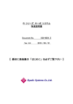
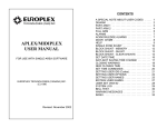
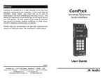
4.7. Virtual memory space access function in Servo amplifier/motor
Servo amplifier/motor compatible with Termini-BUS SIO has EEPROM memory area to memorize axis
control order data, and this area is connected with axis control execution data area inside of servo
amplifier/motor through Window area that can be written and read freely. EEPROM memory area access
function can write and read EEPROM memory area. These operations can be done through Window area.
EEPROM memory
•sŠö”- «ƒ ƒ‚ƒŠ—̈æ
Window area
ƒEƒBƒ“ƒhƒE—̈æ
Execution
•À s—̈æ
Common
‹¤’ʃf [ƒ^
data
memory
‹L‰¯—̈æ
area
Common
data
‹¤’ʃf [ƒ^
Window area
ƒEƒBƒ“ƒhƒE—̈æ
(Bank#00)
(Bank#00)
‹¤’ʃf [ƒ^
Execution data
•À
areasƒf [ƒ^—̈æ
(Bank#30)
(Bank#30)
Position data
ƒ|ƒCƒ“ƒgƒf
[ƒ^
memory
area
‹L‰¯—̈æ
(Position#00)
(Point#00)
Position data
ƒ|ƒCƒ“ƒgƒf
[ƒ^
Window area
ƒEƒBƒ“ƒhƒE—̈æ
(Position#01)
(Bank#01)
ƒ|ƒCƒ“ƒgƒf
[ƒ^
execution data area
•À
sƒf [ƒ^—̈æ
(Position#31)
(Bank#31)
Common data
Position data
Position data
ƒ|ƒCƒ“ƒgƒf
[ƒ^
memory
area
‹L‰¯—̈æ
(Position#01)
(Point#01)
Position data
ƒ|ƒCƒ“ƒgƒf
[ƒ^
memory area
‹L‰¯—̈æ
(Position#N)
(Point#N)
Normally, data edit and memory of EEPROM memory area will be done by Termi-BUS Tools or CTA,
therefore it is not necessary to data transfer by using EEPROM memory area access function in sequence
program. In case of using virtual memory space access function explained later, please refer “4.8. Notes of
COMPACK structure body and virtual memory space” to get information about structure of virtual
memory space and its use.
4.7.1. Random access read out function from virtual memory space
int WINAPI read_svmem(
int axis,
// objective axis number
int address, // virtual memory space address of read out data
long *dst
// pointer to read out data storage area
);
This function is to read out specified data by address from virtual memory space inside of servo amplifier,
and then write into the area specified by pointer “dst”.
Return value
After successful read out, SIO_DONE is returned, for other status, SIO_ERROR will be returned.
DEE-00054E-21
4.7.2. Random access read out function from virtual memory space
int WINAPI write_svmem(
int axis,
// objective axis number
int address,
// write to address in virtual memory space
const long *src
// pointer of write to data storage area
);
This function is to write specified data by pointer “src” into specified area on virtual memory space inside
of servo amplifier by “address”.
Return value
After successful writing, SIO_DONE is returned, for other status, SIO_ERROR will be returned.
4.7.3. Servo system movement parameter write function
int WINAPI write_param(
int axis,
// objective axis number
const COMPACK *src // pointer into COMPACK structure body with writing data
);
This function is to write movement parameters at once written in specified COMPACK structure body by
pointer “src” in common data memory area of EEPROM memory area inside of servo amplifier.
COMPACK structure body is the structured body indicated as below, please refer “4.8. Notes of
COMPACK structure body and virtual memory space” for its usage.
typedef struct {
int address[32];
long data[32];
} COMPACK;
// Offset value arrangement in bank of virtual address (value –1 means to skip
process)
// data arrangement
Return value
After successful writing, SIO_DONE is returned, for other status, SIO_ERROR will be returned.
4.7.4. Servo system movement parameter read out function
int WINAPI read_param(
int axis,
// objective axis number
COMPACK *dst // pointer into COMPACK structure body to read out to
);
This function is to read out movement parameters at once memorized in common data memory area of
EEPROM memory area inside of servo amplifier, and then to write in specified COMPACK structure
body by pointer “dst”. COMPACK structure body is the structured body indicated as below, please refer
“4.8. Notes of COMPACK structure body and virtual memory space” for its usage.
typedef struct {
int address[32];
long data[32];
} COMPACK;
// Offset value arrangement in bank of virtual address (value –1 means to skip
process)
// data arrangement
Return value
After successful read out, SIO_DONE is returned, for other status, SIO_ERROR will be returned.
DEE-00054E-22
4.7.5. PTP movement order data write function
int WINAPI write_point(
int axis,
// objective axis number
int point,
// point number
const COMPACK *src // pointer into COMPACK structure body with written data
);
This function is to write PTP movement order data at once written in specified COMPACK structure body
by pointer “src” into corresponding position data memory area to specified position by “point” in
EEPROM memory area inside of servo amplifier. COMPACK structure body is the structured body
indicated as below, please refer “4.8. Notes of COMPACK structure body and virtual memory space”
for its usage.
typedef struct {
int address[32];
long data[32];
} COMPACK;
// Offset value arrangement in bank of virtual address (value –1 means to skip
process)
// data arrangement
Return value
After successful writing, SIO_DONE is returned, for other status, SIO_ERROR will be returned.
4.7.6. PTP movement order data read out function
int WINAPI read_point(
int axis,
// objective axis number
point,
// position number
COMPACK *dst // pointer into COMPACK structure body read out to
);
This function is to read out PTP movement order data at once memorized in corresponding position data
memory area to position number specified by “point” in EEPROM memory area inside of servo amplifier,
and then to write in specified COMPACK structure body by pointer “dst”. COMPACK structure body is
the structured body indicated as below, please refer “4.8. Notes of COMPACK structure body and
virtual memory space” for its usage.
typedef struct {
int address[32];
long data[32];
} COMPACK;
// Offset value arrangement in bank of virtual address (value –1 means to skip
process)
// data arrangement
Return value
After successful read out, SIO_DONE is returned, for other status, SIO_ERROR will be returned.
DEE-00054E-23
4.7.7. Servo system movement parameter load function
int WINAPI load_param(
int axis
// objective axis number
);
This function is to load movement parameters memorized in common data memory area of EEPROM
memory area inside of servo amplifier into execution area at once via Window area. After execution of
this function, the system will move following movement parameters memorized in EEPROM memory
area. Respective parameters in Window area and execution area will be loaded automatically with
memorized values in EEPROM memory area after the power is turned ON. Therefore it is not necessary
to load movement parameters by using this function, and this function should be used only for
initialization and/or update of movement parameters in EEPROM memory area. It is necessary to write
movement parameters into EEPROM memory area prior to the operation by Termi-BUS Tools or CTA.
Return value
After successful loading, SIO_DONE is returned, for other status, SIO_ERROR will be returned.
4.7.8. Servo system movement parameter save function
int WINAPI save_param(
int axis
// objective axis number
);
This function is to save movement parameters memorized in common data memory area of execution area
into EEPROM memory area inside of servo amplifier at once via Window area. This function should be
used in case when movement parameters updated during execution must be written into EEPROM
memory area as they are.
Return value
After successful save, SIO_DONE is returned, for other status, SIO_ERROR will be returned.
4.7.9. PTP order data save function
int WINAPI save_point(
int axis,
// objective axis number
int point
// position number
);
This function is to save current PTP order data memorized in position data memory area of execution area
into EEPROM memory area inside of servo amplifier at once via Window area. This function should be
used in case when PTP order data updated during execution must be written into EEPROM memory area
as they are.
Return value
After successful save, SIO_DONE is returned, for other status, SIO_ERROR will be returned.
4.7.10. Memory initialization function of servo amplifier
int WINAPI reset_memory(
int axis
// objective axis number
);
This function is to make servo system movement parameter and position data in Window area and
execution area to default value. Set default values are fixed values depending on the model, they are not
values in EEPROM memory area. Execution of “reset_memory” function will update status parameters of
objective axis on global memory to new values.
DEE-00054E-24
4.8. Notes of COMPACK structure body and virtual memory space
Virtual memory space in servo amplifier/motor is divided into SWORD arrangement of 32 factors all named
bank. COMPACK structure body is to make these banks batch operation able, there are 2 groups of
arrangements with 32 factors as indicated as below.
typedef struct {
int address[32];
long data[32];
} COMPACK;
// Offset value arrangement in bank of virtual address (value –1 means to skip
process)
// data arrangement
COMPACK structure body handles 2 factors of address and data as a pair, one number i has address [i] and
data [i] and it means one factor in bank with offset address and data in bank. Item of “address” with –1 value
is disregarded, therefore this enables to partial data pick up and/or partial writing in bank.
Following is data structure of virtual memory space including bank 0 (servo system movement parameter),
bank 1 (PTP movement order data) and status monitor area. It is value that virtual address in the following
list is deducted by base address (top item address of its bank) of bank for offset address in bank that
specifies address field in COMPACK structure body.
Virtual address
(HEX)
00000000
00000001
00000002
00000003
00000004
00000005
00000006
Common parameter
Symbol
CNTM
CNTL
LIMM
LIML
ZONM
ZONL
ORG
Window area
Bank 0 (COM0)
Items
Model
Absolute position coordinate range + side maximum value
Absolute position coordinate range - side maximum value
Software stroke limit value + side
Software stroke limit value - side
Zone border value + side
Zone border value - side
Homing pattern selection code
Bit 0~3: Homing pattern selection code
Bit 7:
Short cut control valid specify bit (1=valid)
00000007 PHSP Motor energizing phase signal detection operation parameter
Bit 0~6: Energizing phase signal detection operation start delay time
specify code
Unit:
1ms
Bit 7:
Energizing phase signal detection movement direction
specify bit
0/1:
= Clockwise / Counter-clockwise
00000008 FPIO PIO function set flag
Bit 0:
0 / 1 = PFIN / INP
Bit 4:
1 = CSTR invalid
Bit 5:
1 = INH + invalid
Bit 6:
1 = INH - invalid
Bit 7:
1 = ILK invalid
R/RC
00000009 BRSL SIO communication speed selection code
0000000A OVCM Homing speed order
Unit: 0.2rpm
0000000B OACC Homing acceleration order
Unit: 0.1r/min/ms
0000000C RTIM Slave transmitter activation minimum delay time parameter
Unit: 1ms
0000000D INP In position width default value
DEE-00054E-25
0000000E VCMD Speed order default value
Unit: 0.2 rpm
0000000F ACMD Acceleration order default value
Unit: 0.1 r/min/ms
00000010 SPOW Electrical current limitation default value for positioning stop
00000011 DPOW Electrical current limitation default value during movement
00000012 PLG0 Servo gain number default value
00000013 MXAC Maximum acceleration specify flag default value
00000014 CPAC CP control mode acceleration constant (reservation for future
expansion)
00000015 PSWT Special specification (reservation)
Reservation for future expansion
00000018 ZRMK Homing prohibition flag (B series absolute model only)
00000019 ODPW Homing current limitation value
Unit: 1ms
0000001A OTIM Homing time out value
Servo
gain
number
default
value
for
positioning stop
0000001B PLG1
0 = Light load
0000001C PLJL Servo gain table selection switch by load inertia
inertia
1 = Middle
load inertia
2 = Heavy
load inertia
0000001D FLSL Type selection flag for current order filter
0 = Primary low pass filter
1 = band elimination filter 0 = Light load inertia
0000001E FLFC LP cut off frequency/BEF central frequency of current order
Total write number of times in EEPROM memory area (Area A)
0000001F
Position data window area
bank 1 (PNT1)
Symbol
Data
00000400 PCMD Absolute position coordinate target positioning stop
00000401 FLGP Axis movement parameter default / Position data selection flag
Position data valid
Bit 7:
In position width
Bit 6:
Speed, acceleration, ultimate acceleration
Bit 5:
Electrical current limitation value
Bit 4:
Servo gain number
B
Models
Reservation for future expansion
00000402
00000403 INP In position width / Push force maximum pushing depth
Unit: 0.2 rpm
00000404 VCMD Speed order
Acceleration
order
Unit: 0.1 r/min/ms
00000405 ACMD
00000406 SPOW Electrical current limitation value for positioning stop / Electrical
current limitation value for push movement
00000407 DPOW Electrical current limitation value during movement
00000408 PLG0 Servo gain number value
00000409 MXAC Ultimate acceleration specify flag
Bit 0:
1 = Ultimate acceleration
0000041F
B
R/RC
R/RC
B
B
B
Address (HEX)
00000411 PLG1 Servo gain number of positioning stop
R/RC
B/R
R/RC
B
Total write number of times in EEPROM memory area (Area A)
DEE-00054E-26
Address (HEX)
00006800
00006801
00006802
00006803
00006804
00006805
00006806
00006807
00006808
00006809
Address (HEX)
00006C00
00006C01
00006C02
00006C03
00006C04
00006C05
Amplifier / Motor type monitor
Bank 26 (TYPE)
Models
Symbol
Data
ROM Model code and ROM version code
RC
S/N Serial number
Servo
amplifier
model
name
character
digits,
Number
1
group
4
characters
AMP1
AMP2 Servo amplifier model name character digits, Number 2 group 4 characters
AMP3 Servo amplifier model name character digits, Number 3 group 4 characters
Reservation
Servo
motor model name character digits, Number 1 group 4 characters
MOT1
MOT2 Servo motor model name character digits, Number 2 group 4 characters
MOT3 Servo motor model name character digits, Number 3 group 4 characters
Reservation
Monitor relating data
bank 27 (MONI)
Symbol
Data
A_FL Flag of analog monitor (Note 1)
A_AD Address of analog monitor (fixed value 7401) (Note 1)
H_DT Trace data specify address
H_SC Sampling distance for trace data
Set value n : (n+1)*500µs
H_WR Maximum written address for trace data
All area write completion when top bit is 1
H_BY Trace data type
BYTE = 1, WORD = 2, LWORD = 4
Models
R
R
B/RC
B/RC
B/RC
B/RC
(Note 1) Dyadic uses only, please do not use this.
Address (HEX)
10000000
10000001
.
********
Address (HEX)
00007000
00007001
00007002
00007003
00007004
00007005
00007006
00007007
00007008
00007009
Storage area for trace data
Symbol
First data
2nd data
.
Last data
Data
Alarm monitor area
bank 28 (ALRM)
Symbol
Data
WARN Final detected warning code
HYS0 Final detected alarm code
HYS1 Preceding detected alarm code one time before last
HYS2 Preceding detected alarm code 2 times before last
HYS3 Preceding detected alarm code 3 times before last
HYS4 Preceding detected alarm code 4 times before last
HYS5 Preceding detected alarm code 5 times before last
HYS6 Preceding detected alarm code 6 times before last
HYS7 Preceding detected alarm code 7 times before last
ARMA Data address where execution was something wrong.
Models
Models
DEE-00054E-27
Address (HEX)
00007400
00007401
00007402
00007403
00007404
00007405
00007406
00007407
Internal status monitor area
bank 29 (STAT)
Symbol
Data
PNOW Absolute position counter current position
VNOW Current speed monitor
Reservation for future expansion
STAT Internal status flag
ALRM Current alarm/Warning code
PIO input port monitor
PI
PIO output port monitor
PO
Status monitor of SW1 (Rotary), SW2 (DIP)
SW
Bit 4~7: 4 bit status of SW1 (Axis number)
Bit 3:
6 of SW2 (1 / 0 = ON / OFF)
Bit 2:
5 of SW2 (1 / 0 = ON / OFF)
Bit 1:
4 of SW2 (1 / 0 = ON / OFF)
Bit 0:
3 of SW2 (1 / 0 = ON / OFF)
00007408 STA2 Bit 0:
00007409
0000740A
0000740B
0000740C
0000740D
WADR
ROM
A/D0
A/D1
A/D2
Homing flag
Models
B/R
B/R
1 = Homing is in execution
Write to address counter by 4 command
Model code and ROM version
Analog value for inspection
Analog value for inspection
Analog value for inspection
R/RC
R/RC
R/RC
Output alarm for 78H or
00007412 OLLV Current value of over load detection,
greater
00007413 LVPK Peak hold value of over load detection level
00007414 ICMD Internal electrical current order value (torque order value)
100/Current rating
00007415 PNTM Current position number monitor (0~255)
B
B
DEE-00054E-28