1
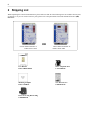
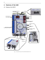
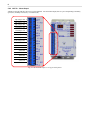
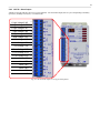
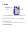
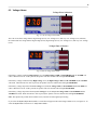
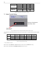
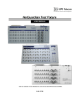
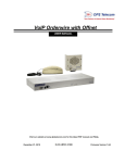
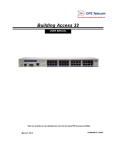
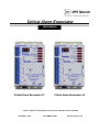
Critical Alarm Enunciator
USER MANUAL
Critical Alarm Enunciator 33
Critical Alarm Enunciator 42
Visit our website at www.dpstelecom.com for the latest PDF manual and FAQs.
December 9, 2004
D-OC-UM04C.09100
Firmware Version 1.0F
Revision History
December 9, 2004
Critical Alarm Enunciator Manual
D-OC-UM04C.09100 released.
This document contains proprietary information which is protected by copyright. All rights are reserved. No part of this
document may be photocopied without prior written consent of DPS Telecom.
All software and manuals are copyrighted by DPS Telecom. Said software and manuals may not be reproduced, copied,
transmitted or used to make a derivative work, by either mechanical, electronic or any other means in whole or in part,
without prior written consent from DPS Telecom, except as required by United States copyright laws.
© 2004 DPS Telecom
Notice
The material in this manual is for information purposes and is subject to change without notice. DPS Telecom shall not be
liable for errors contained herein or consequential damages in connection with the furnishing, performance, or use of this
manual.
Contents
Visit our website at www.dpstelecom.com for the latest PDF manual and FAQs
1 Introduction
1
2 Shipping List
2
3 Specifications
3
4 Features of the CAE
4
4.1 Features of the CAE 33
4
4.2 Features of the CAE 42
5
5 Installation
6
5.1 Tools Needed
6
5.2 Mounting
6
5.3 Power Connection
6
5.4 Alarm Connections
7
5.4.1
Alarm Inputs
7
5.4.2
CAE 33 - Alarm Output
8
5.4.3
CAE 42 - Alarm Output
9
6 Operation
10
6.1 Discrete Alarms
10
6.2 Voltage Alarms
11
6.3 3-Digit Voltage Readout
12
6.4 Test Mode
13
7 Configuration
14
7.1 Alarm Input Polarity Settings
15
7.2 Major/Minor (Mj/Mn) Mode
15
7.3 Voltage Threshold Settings
16
8 Troubleshooting
17
9 Technical Support
17
1
1 Introduction
Critical Alarm Enunciator 33
Critical Alarm Enunciator 42
The Critical Alarm Enunciator is a local alarm notification device that is available in two models: the CAE 33 and the CAE
42. The CAE 33 monitors three discrete alarms and three battery plant low voltage alarms. The CAE 42 monitors two
discrete alarms and four voltage alarms. All information in this manual applies to all CAE models, unless otherwise noted.
The CAE receives alarm input from monitored devices, provides audiovisual notification to local personnel, and then relays
alarms to your existing alarm collection equipment. The CAE provides local notification of alarms through its integrated
front-panel LED voltage meter, 6 alarm notification LEDs, and an audible speaker signal. The speaker can be silenced by
pressing the LOCAL ACK (acknowledge) button on the bottom of the unit.
You can reverse the input polarity of the discrete alarms, set the voltage thresholds of the voltage alarms, and select between
Normal and Major/Minor(Mj/Mn) alarm modes by using the configuration DIP switches on the top panel of the unit. See
Section 7, "Configuration," for instructions on setting the DIP switches.
2
2 Shipping List
While unpacking the Critical Alarm Enunciator, please make sure that all of the following items are included. If some parts
are missing, or if you ever need to order new parts, please refer to the part numbers listed and call DPS Telecom at (800)
622-3314.
OR
Critical Alarm Enunciator 33
D-PK-CAE33-12001
Critical Alarm Enunciator 42
D-PK-CAE42-12001
User Manual
D-OC-UM04C.09100
One 1 Amp GMT Fuse
1-741-01000-00
Mounting Template
D-OC-CAEMNT
Two Wood Screws
1-000-80750-50
Power Screw Lug Barrier Plug
1-820-00862-00
3
3 Specifications
Dimensions:
5" H x 4" W x 2" D (12.7 cm x 10.2 cm x 5.1 cm)
Weight:
3 lbs (1.4 kg)
Mounting:
Wall mount
Power Input:
+24 VDC or –48 VDC
Current Draw:
+24VDC unit:
–48VDC unit:
Fuse:
1 Amp GMT
Discrete Inputs:
CAE 33:
CAE 42:
Alarm Detection Speed:
100 msec
Analog Inputs:
1 (battery plant monitoring input)
550 mA
250 mA
3
2 (3 in Mj/Mn Mode)
Analog Input Range (+24 VDC unit): +21.4 VDC to +30 VDC
Analog Input Range (–48 VDC unit): –44 to –56.5 VDC
Control Outputs:
6 (alarm relay outputs)
CAE 33:
3 threshold level alarms
3 alarm relays
CAE 42:
4 threshold level alarms
2 alarm relays
Maximum Current:
1 Amp
Visual Alarm Display:
6 unicolour LEDs, voltage readout
Speaker output volume:
0 - 85 dB @ 1 meter
Operating Temperature:
32° to 140° F (0° - 60° C)
Operating Humidity:
0%–95% noncondensing
4
4 Features of the CAE
4.1 Features of the CAE 33
3 Digit Voltage Readout/
Test Voltage
Config DIP
Switches 1 - 8
8 7
3 2 1
HV LED
Critical Alarms for
Local Visibility
LV1 LED
LV2 LED
Critical Alarm
Indicators
Voltage Simulation
Wheel
Audible Alarm
Speaker
Alarm Relays to
Reporting Center (NOC)
Momentary Voltage
Test Mode
Power Feed
Fuse
Fuse Alarm
Acknowledgement
button
Volume Control
Voltage Simulation wheel
Momentary Voltage Test Mode button
Power Feed
Fuse
Acknowledgement button
Volume control
Fig. 1. The features of the Critical Alarm Enunciator 33
5
4.2 Features of the CAE 42
3 Digit Voltage Readout/
Test Voltage
Config DIP
Switches 1 - 8
8 7
3 2 1
HV2 LED
Critical Alarms for
Local Visibility
HV1 LED
LV1 LED
LV2 LED
Critical Alarm
Indicators
Voltage Simulation
Wheel
Audible Alarm
Speaker
Alarm Relays to
Reporting Center (NOC)
Momentary Voltage
Test Mode
Power Feed
Fuse
Fuse Alarm
Acknowledgement
button
Volume Control
Voltage Simulation wheel
Momentary Voltage Test Mode button
Power Feed
Fuse
Acknowledgement button
Volume control
Fig. 2. The features of the Critical Alarm Enunciator 42
6
5 Installation
5.1 Tools Needed
To install the Critical Alarm Enunciator, you'll need the following tools:
Wire Strippers/Cutter
Small Standard No. 2 Screwdriver
5.2 Mounting
To mount the Critical Alarm Enunciator, drive the two included wood mount screws. Mount the CAE by attaching the
mounting template cutout to the back of the unit and placing the unit on the two wood screws. Press the unit back to secure it
to the wall.
5.3 Power Connection
To connect the Critical Alarm Enunciator to a power source, follow these steps:
1. Remove the fuse from the bottom panel of the CAE and make sure that the power supply to the unit is off.
2. Remove the screw lug barrier plug from the bottom panel of the CAE.
3. For a CAE +24VDC unit, connect a +24 VDC line to the +24V terminal and a battery ground to the GND terminal of
the screw lug. For a CAE –48VDC unit, connect a –48VDC line to the –48V terminal and a battery ground to the
GND terminal of the screw lug. Seat the barrier screws firmly, but be careful not to nick the bare wire.
4. Push the plug firmly back into its socket. Note that this connection is keyed and the plug must be properly aligned
within the socket.
5. With the CAE fuse still removed, turn on the power supply.
6. On a CAE +24VDC unit, the voltmeter should read between +21.4 and +30 VDC. CAE –48VDC unit, the voltmeter
should read between –44 to –56.5 VDC. If the reading is outside this range, check your power supply.
7. Do not power the unit until all connections have been made.
8. Insert the fuse to power the CAE.
7
5.4 Alarm Connections
Alarm Input
Alarm Output
Fig. 3. Alarm Input and Alarm Output connectors
Alarm connections are located on the left side panel of the Critical Alarm Enunciator. Alarm Input and Alarm Output are
screw-lug connectors.
5.4.1 Alarm Inputs
Alarm inputs are connected to the CAE 33 and CAE 42 via screw-lug terminals. The Alarm Inputs in the CAE 33 and 42 are
identical, see Figure 4 for example.
Alarm 1
1
Ground
2
Alarm 2
1
Ground
2
Alarm 3
1
Ground
2
Fig. 4. Alarm Input pinouts
8
5.4.2 CAE 33 - Alarm Output
Alarms are relayed from the CAE via screw-lug terminals. For each alarm output, there is a pin corresponding to normally
open (NO), normally closed (NC), or common (CO).
High Voltage 1 NO
1
High Voltage 1 CO
2
High Voltage 1 NC
1
Low Voltage 1 NO
2
Low Voltage 1 CO 1
Low Voltage 1 NC 2
V Low Voltage 2 NO 1
V Low Voltage 2 CO 2
V Low Voltage 2 NC 1
Alarm 1 NO 2
Alarm 1 CO 1
Alarm 1 NC 2
Alarm 2 NO 1
Alarm 2 CO 2
Alarm 2 NC 1
Alarm 3 NO 2
Alarm 3 CO 1
Alarm 3 NC 2
Fig. 5. CAE 33 alarm output screw-lug terminal pinouts
9
5.4.3 CAE 42 - Alarm Output
Alarms are relayed from the CAE via screw-lug terminals. For each alarm output, there is a pin corresponding to normally
open (NO), normally closed (NC), or common (CO).
V High Voltage 2 NO
1
V High Voltage 2 CO
V High Voltage 2 NC
2
High Voltage 1 NO
2
High Voltage 1 CO
1
High Voltage 1 NC
2
Low Voltage 1 NO
1
Low Voltage 1 CO
2
Low Voltage 1 NC
1
V Low Voltage 2 NO
2
V Low Voltage 2 CO
1
V Low Voltage 2 NC
2
Alarm 1 NO
1
Alarm 1 CO
2
Alarm 1 NC
1
Alarm 2 NO
2
Alarm 2 CO
1
Alarm 2 NC
2
1
Fig. 6. CAE 42 alarm output screw-lug terminal pinouts
10
6 Operation
6.1 Discrete Alarms
Monitored Equipment
Alarm Collection
Equipment
Discrete Alarm Input
Alarm Output
Discrete
Alarm Indicators
Master
Fig. 7. The CAE receives input from monitored devices, provides local notification, and relays alarms to existing alarm
collection equipment.
The CAE receives alarm input from monitored devices, provides audiovisual notification to local personnel, and then relays
alarms to your existing alarm collection equipment.
When the CAE receives an alarm input, the LED corresponding to the activated alarm point will FLASH RED and the
speaker will sound.
To acknowledge the alarm and silence the speaker, press the LOCAL ACK button on the bottom panel of the unit. The alarm
LED will turn SOLID RED to indicate that the alarm has been acknowledged. The speaker only sounds when an alarm
occurs, and will not sound again upon clearing.
The speaker is set at the factory to the maximum volume. You may adjust the volume of the alarm with the Volume Control
wheel located on the right side of the CAE.
The input polarity of the discrete alarms can be reversed using the configuration DIP switches on the top panel. See Section
7.1, "Alarm Input Polarity Settings," for instructions.
11
6.2 Voltage Alarms
Voltage Alarm Indicators
Fig. 8. CAE 33 voltage alarm LEDs.
The CAE 33 has three voltage alarms: High Voltage (HV1), Low Voltage (LV1) and Very Low Voltage (LV2). Whereas,
the CAE 42 has four voltage alarms: High Voltage (HV2), High Voltage (HV1), Low Voltage (LV1) and Very Low Voltage
(LV2).
Voltage Alarm Indicators
Fig. 9. CAE 33 voltage alarm LEDs.
If the battery voltage reaches the High Voltage level, the High Voltage 1 LED will FLASH RED and the ALARM will
sound. When the LOCAL ACK is pressed, the speaker will cease and the LED will light SOLID RED.
If the battery voltage reaches the Very High Voltage level, the High Voltage 2 LED will FLASH RED and the ALARM
will sound. When the LOCAL ACK is pressed, the speaker will cease and the LED will light SOLID RED.
If the battery voltage drops below the Low Voltage level, the Low Voltage LED will FLASH RED and the ALARM will
sound. When the LOCAL ACK is pressed, the speaker will cease and the LED will light SOLID RED.
If the battery voltage drops below the Very Low Voltage level, the Very Low Voltage LED will FLASH RED and the
ALARM will sound. When the LOCAL ACK is pressed, the speaker will cease and the LED will light SOLID RED.
Note: The speaker only sounds when an alarm occurs, and will not sound again upon clearing.
If you select the Mj/Mn (Major/Minor) Mode, a second dot will appear in the LED voltage readout screen, see Figure 10. To
select the Mj/Mn Mode see Section 7.2 "Major/Minor Mode."
12
Fig. 10. Second dot indicates Mj/Mn Mode
You can adjust the voltage alarm thresholds to use the CAE with either VRLA or flooded system battery plants.
CAE
Battery
Type
LV1 (Low
Voltage 1)
LV2 (Low
Voltage 2)*
HV1 (High
Voltage 1)
HV2 (High
Voltage 2)*
24
VDC
–48
VDC
Flooded
VRLA
Flooded
VRLA
25.4
26.0
–51.8
–53.0
22.4
23.0
–44.8
–46.0
27.9
28.5
–54.3
–55.5
28.4
29.0
–54.8
–56.0
Table A.. Voltage Threshold settings
* = only available on CAE 42
For instructions on adjusting voltage alarm thresholds, see Section 7.3, "Voltage Threshold Settings."
6.3 3-Digit Voltage Readout
Fig. 11. Voltage readout/Test panel.
The 3-digit voltage readout on the front of the CAE allows for a visual confirmation of the current voltage of the unit without
the need to attach an outside voltometer to the unit. When powered up, the voltage readout will display rLA or Fld to let you
know that the unit is in either VRLA or Flooded mode.
On a CAE +24 VDC, the voltage readout can visually display readings between 21.4V and 30.0V. On a CAE –48 VDC, the
voltage readout can visually display readings between –44.0V and –56.5V. If the voltage reading should fall outside of this
range, the closest displayable voltage (21.4 or 30.0) will flash on the display, followed by under bars ( _ _ _ ) if the voltage is
below 21.4V (–44.0V), or over bars ( ¯ ¯ ¯ ) if the voltage is above 30.0V(–56.5V).
On power up, the CAE will display one of two short messages in the voltage readout to let the user know what mode the unit
is in. The message beings: dps cae 33 (or 42) 1.0f (the firmware version) and the voltage readout settings — see Table B for
voltage readout.
13
CAE
Battery Type
24
VDC
48
VDC
rLA (VRLA)
Fld (Flooded)
rLA (VRLA)
Fld (Flooded)
HV1 (High
Voltage 1)
27.9
28.5
54.3
55.5
HV2 (High
Voltage 2)*
28.4
29.0
54.8
56.0
LV1 (Low
Voltage 1)
25.4
26.0
51.8
53.0
LV2 (Low
Voltage 2)*
22.4
23.0
44.8
46.0
Battery Type
rLA (VRLA)
Fld (Flooded)
rLA (VRLA)
Fld (Flooded)
Table B.. Voltage readout settings
* = only available on CAE 42
To display the mode message again, press and hold the LOCAL ACK button for three seconds. To skip this message hold the
LOCAL ACK button before powering up.
6.4 Test Mode
Your Critical Alarm Enunciator comes equipped with a built-in voltage test mode. This mode allows testing of threshold
crossings to send alarms to the NOC that could not otherwise be tested without running the battery down—a great feature for
alarm audits.
Momentary Voltage Test Mode button
Voltage Simulation wheel
Fig. 12. Using the CAE Test mode.
To begin the test mode, press the Momentary Voltage Test Mode button located on the right side of the CAE. Rotate the
Voltage Simulation Wheel until the readout simulates a High, Low, or Very Low voltage reading. When the appropriate
threshold has been achieved, an alarm will notify you the test was successful.
The CAE is factory configured with the volume at maximum.
Note: you will not be able to test HV2 after 23.5 volts or HV1 after 23.2 volts.
14
7 Configuration
DIP switch 8:
Select Battery
Plant Voltage
Threshold
8
7
6
5
4
3
2
DIP switches 1 - 3:
Reverse Alarm
Input Polarity
1
DIP switches 4 & 5:
Not Used
DIP switch 6:
Reserved
Factory Pre-set
Leave in Off
Position
DIP switch 7:
Mj/Mn Mode
Fig. 13. Configuration DIP switches
All user-adjustable options on the Critical Alarm Enunciator can be set using the DIP switches on the left side panel of the
unit. The CAE ships with all DIP switches set in the DOWN or OFF position, which represents the default settings for all
options.
When the DIP switches are used to configure the CAE, the unit will automatically reboot itself so that the changes
take place immediately. A scrolling message will appear with most of your new settings in the Voltage Readout LED
screen.
Table B summarizes all of the CAE's DIP switch settings.
1
Function
DOWN
(default)
UP
2
3
Discrete Alarm Input
Polarity Selection
Alarm
1 NO
Alarm
1 NC
Alarm
2 NO
Alarm
2 NC
Alarm 3
NO
Alarm 3
NC
DIP Switches
4
5
6
Reserved
NOT
USED
(Factory
pre-set:
Do not
change)
Table B. DIP switch options
7
8
Alarm
Mode
Voltage
Threshold
Selection
Normal
VRLA
Major/Minor
FLOODED
15
7.1 Alarm Input Polarity Settings
Alarm 2
Alarm 1
Alarm 3
Switch Up = Normally Closed
3
2
1
Switch Down= Normally Open
Fig. 14. DIP switches 1–4 set the discrete alarm inputs for normal or reversed polarity
The polarity of the three discrete alarm inputs can be reversed using DIP switches 1–3. The DIP switch numbers match the
numbers of the alarms they control, so Switch 1 controls Alarm 1, Switch 2 controls Alarm 2, and Switch 3 controls Alarm 3.
When the switch is angled DOWN, the alarm input is Normally Open. (This is the DEFAULT setting.) When the switch is
angled UP, the alarm input is Normally Closed.
7.2 Major/Minor (Mj/Mn) Mode
7
DIP switch 7:
Mj/Mn Mode
Fig. 15. Adjust DIP Switch 7 to select the Mj/Mn Mode.
When switch 7 is Down, the Normal mode is selected. In Normal mode, the CAE 42 can monitor four voltage alarms and
two discrete alarms. The CAE 33 monitors three voltage alarms and three alarm points. The Alarm inputs are echoed 1 to 1
to the Alarm Outputs.
When switch 7 is UP, the Mj/Mn mode is selected. A second dot will appear in the LED voltage readout screen, see Section
6.2 "Voltage Alarms" for example. If there is an alarm, the Alarm 1 LED will flash a minor alarm notification. If there are
two or more alarms, then the Alarm 2 LED will flash a major alarm. Alarm 1 LED will not flash, but it will be on when a
major alarm occurs. Press the LOCAL ACK (acknowledge) button to silence the speaker and acknowledge the alarm.
16
Alarm Mode
CAE 33
LED Flash
CAE 42
LED Flash
Normal Mode
1–1
2–2
3–3
Alarm 1
Alarm 2
Alarm 3
1–1
2–2
—
Alarm 1
Alarm 2
—
> 1 Minor (Mn)
Alarm 1
>1
Alarm 1
> 2 Major (Mj)
Alarm 2
>2
Alarm 2
Mj/Mn Mode
Table C. Alarm mode visual notification settings
7.3 Voltage Threshold Settings
Switch Up = Flooded System
8
Switch Down = VRLA
Voltage Threshold
Selection Switch
Fig. 16. DIP Switch 8 selects voltage thresholds for different battery plants
You can adjust the voltage alarm thresholds to use the CAE with either VRLA or flooded system battery plants using DIP
Switch 8.
CAE
24 VDC
–48 VDC
Battery Type
LV2 (Low
Voltage 2)
LV1 (Low
Voltage 1)
Float
HV1 (High
Voltage 1)
HV2 (High
Voltage 2)*
Flooded
VRLA
Flooded
VRLA
22.4
23.0
–44.8
–46.0
25.4
26.0
–51.8
–53.0
26.4
27.0
–52.8
–54.0
27.9
28.5
–54.3
–55.5
28.4
29.0
–54.8
–56.0
Table D. Voltage threshold settings
* = only available on CAE 42
When Switch 8 is angled DOWN, the VRLA thresholds are selected. (This is the DEFAULT setting.)
When Switch 8 is angled UP, the FLOODED SYSTEM thresholds are selected.
17
8 Troubleshooting
Alarm Notification: If you experience problems with CAE alarm notification, test the unit by simulating an alarm.
Reversing the polarity of the alarm and the associated DIP switches is an easy way to test alarm notification.
LED Flash: Each alarm LED should FLASH RED when an event occurs until the LOCAL ACK button is pressed. If the
LED does not flash red, check the LED light and the power pack.
Speaker Sound: The speaker should sound each time an alarm notification occurs. If you notice the red light flashing but
don't hear sound from the speaker, make sure the volume is turned up.
Acknowledge Button: The LOCAL ACK button will stop the LED flashing and the speaker notification each time an alarm
is cleared. If the LOCAL ACK button does not disable both the alarm and the speaker, check the wiring connection to the
LOCAL ACK button.
Fuse Alarm: If for any reason the power fuse of the CAE should fail, the Fuse Alarm (FA) LED on the front of the unit will
light. Remove failed fuse and replace with a new one.
9 Technical Support
DPS Telecom products are backed by our courteous, friendly Technical Support representatives, who will give you the best
in fast and accurate customer service. To help us help you better, please take the following steps before calling Technical
Support:
1. Check the DPS Telecom website.
You will find answers to many common questions on the DPS Telecom website, at
http://www.dpstele.com/products/cae/support.html
Look here first for a fast solution to your problem.
2. Prepare relevant information.
Having important information about your DPS Telecom product in hand when you call will greatly reduce the time it
takes to answer your questions. If you do not have all of the information when you call, our Technical Support
representatives can assist you in gathering it. Please write the information down for easy access. Please have ready
your User Manual and hardware serial number.
3. Have access to troubled equipment.
Please be at or near your equipment when you call DPS Telecom Technical Support. This will help us solve your
problem more efficiently.
4. Call during Customer Support hours.
Customer support hours are Monday through Friday, from 7 A.M. to 6 P.M., Pacific time. During these hours
Technical Support representatives are on duty in our fully equipped simulation lab.
Emergency Assistance: Emergency assistance is available 24 hours a day, 7 days a week. For emergency assistance after
hours, allow the phone to ring until it is answered with a paging message. You will be asked to enter your phone number. An
on-call technical support representative will return your call as soon as possible.
Warranty
DPS Telecom warrants, to the original purchaser only, that its products a) substantially conform to DPS' published
specifications and b) are substantially free from defects in material and workmanship. This warranty expires two years from
the date of product delivery with respect to hardware and ninety days from the date of product delivery with respect to
software. If the purchaser discovers within these periods a failure of the product to substantially conform to the specifications
or that the product is not substantially free from defects in material and workmanship, the purchaser must promply notify
DPS. Within reasonable time after notification, DPS will endeavor to correct any substantial non-conformance with the
specifications or substantial defects in material and workmanship, with new or used replacement parts. All warranty service
will be performed at the company's office in Fresno, California, at no charge to the purchaser, other than the cost of shipping
to and from DPS, which shall be the responsiblity of the purchaser. If DPS is unable to repair the product to conform to the
warranty, DPS will provide at its option one of the following: a replacement product or a refund of the purchase price for the
non-conforming product. These remedies are the purchaser's only remedies for breach of warranty. Prior to initial use the
purchaser shall have determined the suitability of the product for its intended use. DPS does not warrant a) any product,
components or parts not manufactured by DPS, b) defects caused by the purchaser's failure to provide a suitable installation
environment for the product, c) damage caused by use of the product for purposes other than those for which it was designed,
d) damage caused by disasters such as fire, flood, wind or lightning unless and to the extent that the product specification
provides for resistance to a defined disaster, e) damage caused by unauthorized attachments or modifications, f) damage
during shipment from the purchaser to DPS, or g) any abuse or misuse by the purchaser.
THE FOREGOING WARRANTIES ARE IN LIEU OF ALL OTHER WARRANTIES, EXPRESS OR IMPLIED,
INCLUDING BUT NOT LIMITED TO THE IMPLIED WARRANTIES OF MERCHANTABILITY AND FITNESS FOR
A PARTICULAR PURPOSE.
In no event will DPS be liable for any special, incidental, or consequential damages based on breach of warranty, breach of
contract, negligence, strict tort, or any other legal theory. Damages that DPS will not be responsible for include but are not
limited to, loss of profits; loss of savings or revenue; loss of use of the product or any associated equipment; cost of capital;
cost of any substitute equipment, facilities or services; downtime; claims of third parties including customers; and injury to
property.
The purchaser shall fill out the requested information on the Product Warranty Card and mail the card to DPS. This card
provides information that helps DPS make product improvements and develop new products.
For an additional fee DPS may, at its option, make available by written agreement only an extended warranty providing an
additional period of time for the applicability of the standard warranty.
Technical Support
If a purchaser believes that a product is not operating in substantial conformance with DPS' published specifications or there
appear to be defects in material and workmanship, the purchaser should contact our technical support representatives. If the
problem cannot be corrected over the telephone and the product and problem are covered by the warranty, the technical
support representative will authorize the return of the product for service and provide shipping information. If the product is
out of warranty, repair charges will be quoted. All non-warranty repairs receive a 90-day warranty.
“We protect your network like
your business depends on it” TM
www.dpstelecom.com
4955 E. Yale • Fresno, CA 93727
(559) 454-1600 • (800) 622-3314 • (559) 454-1688 fax