1
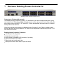
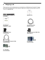
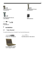
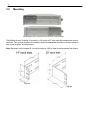
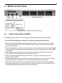
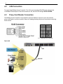
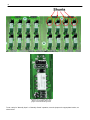
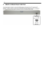
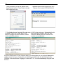
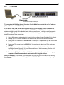
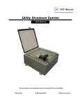
Building Access 32
USER MANUAL
Visit our website at www.dpstelecom.com for the latest PDF manual and FAQs.
March 7, 2013
D-UM-BACTL.12002
Revision History
March 7, 2013
Added COS Mode, Elevator, Floor Lighting, and Port
Customization
August 8, 2011
Added "Exit Mode"
February 10, 2011
Included instructions for using In-Facility Elevator Mode
November 12, 2010 Miscellaneous updates
August 27, 2010
Preliminary release
This document contains proprietary information which is protected by copyright. All rights are reserved. No part of this
document may be photocopied without prior written consent of DPS Telecom.
All software and manuals are copyrighted by DPS Telecom. Said software and manuals may not be reproduced, copied,
transmitted or used to make a derivative work, by either mechanical, electronic or any other means in whole or in part, without
prior written consent from DPS Telecom, except as required by United States copyright laws.
© 2011 DPS Telecom
Notice
The material in this manual is for information purposes and is subject to change without notice. DPS Telecom shall not be
liable for errors contained herein or consequential damages in connection with the furnishing, performance, or use of this
manual.
Contents
Visit our w ebsite at w w w .dpstelecom .com for the latest PDF m anual and FAQs
1
Overview: Building Access Controller 32
1
2
Shipping List
2
3
Installation
3
3.1
Tools Needed
3
3.2
Mounting
4
4
BACTL 32 Front Panel
5
4.1
Power Connection (+24VDC)
5
4.2
LAN Connection
6
4.3
Proxy Card Reader Connection
6
4.4
Adjusting Relay Operation
7
5
BACTL 32 Back Panel Craft Port
10
6
Quick Start: How to Connect to the BACTL 32
11
6.1
...via Craft Port (using TTY Interface)
11
6.2
...via LAN
13
7
Quick Start: How to Setup BACTL 32 in T/Mon
14
8
Quick Start: Access Web Browser Interface
16
8.1
16
9
Logging on to the BACTL 32
Web Browser (Editing)
17
9.1
System
17
9.2
Edit BAC1 (for Doors 1-16)
19
9.2.1
Customize Port Options
19
9.3
Edit BAC2 (for Doors 17-32)
20
9.4
Logon
20
9.5
Ethernet
21
9.6
Filter IPA
22
9.7
Ports
23
9.8
Date and Time
24
9.9
NVRAM
25
9.10 Reboot
25
9.11 Web Browser (Monitoring)
26
9.11.1
Mon BAC1
26
9.11.2
Mon BAC2
26
10 In-Facility Broadcast
27
10.1 Elevator Mode
30
10.2 Exit Mode
33
11 Front and Back Panel LEDs
34
12 Upgrading Firmware via COM Port
35
13 Technical Support
36
14 End User License Agreement
37
1
1
Overview: Building Access Controller 32
Building Access Controller 32 (BACTL 32)
Control up to 32 doors with one unit
The Building Access Controller 32 (BACTL 32) interfaces to your door controllers and alarms, proxy
card readers, and T/Mon Alarm Master. When someone waves a proxy card in front of the reader, the
entry code is sent to the BACTL 32. The BACTL 32 then authenticates the code to see if it is valid for
that specific door at that time.
While entry decisions are made by the Building Access Controller 32, the T/Mon is notified of entry
activities and logs any intrusion alarms. The T/Mon is also responsible for provisioning the BACTL 32
with valid access codes.
Building Access Controller 32 features
Controls up to 32 entry points
Supports proxy card entry
Easy hookup via standard RJ45 connector (1 per door)
LAN communication with T/Mon
Relay locks and unlocks each door
Alarm point monitors each door for open and close
2
2
Shipping List
Please make sure all of the following items are included with your Building Access Controller 32. If parts
are missing, or if you ever need to order new parts, please refer to the part numbers listed and call DPS
Telecom at 1-800-622-3314.
Building Access Controller 32
D-PK-BACTL
Resource CD
User Manual
D-UM-BACTL.12002
14 ft. Ethernet Cable
D-PR-923-10A-14
3/4-Amp GMT Fuses
2-741-00750-00
Lg. Power Connector (Main Pwr)
2-820-00862-02
x2
6 ft. DB9M-DB9F Download Cable
D-PR-045-10A-04
x2
19" Rack Ears
D-CS-325-10A-00
23" Rack ears
D-CS-325-10A-01
3
x4
x2
Four 3/8" Ear Screws
1-000-60375-05
Two Metric Rack Screws
2-000-80750-03
x2
Two Standard Rack Screws
1-000-12500-06
Pads
2-0150-00030-00
x 32
32 Diodes
2-302-04002-00
3
3.1
Installation
Tools Needed
To install the Building Access Controller 32, you'll need the following tools:
Phillips No. 2 Screwdriver
PC with terminal emulator,
such as HyperTerminal
Small Standard No. 2 Screwdriver
4
3.2
Mounting
The Building Access Controller 32 can be flush or rear-mounted
The Building Access Controller 32 mounts in a 19" rack or a 23" rack using the provided rack ears for
each size. Two rack ear locations are available. Attach the appropriate rack ears in the flush-mount or
rear-mount locations, as shown above.
Note: Rack ears can be rotated 90° for wall mounting or 180º for other mounting options (not shown).
Fig. 4.2
Fig. 4.3
5
4
BACTL 32 Front Panel
Building Access Controller 32 panel connections
4.1
Power Connection (+24VDC)
The Building Access Controller 32 is powered by a single terminal barrier plug power connector.
To connect the Building Access Controller 32 to a power supply, follow these steps:
1. Always use safe power practices when making power connections. Be sure to remove fuses from
the fuse distribution panel, as well as the back of the Building Access Controller 32, before making
your power connections.
2. Use the grounding lug to connect the unit to earth ground. The grounding lug is next to the symbol
. Insert the eyelet of the earth ground cable between the two bolts on the grounding lug (Ground cable
not included).
3. Insert a battery ground into the power connector plug's right terminal and tighten the screw; then
insert a battery line to the plug's left terminal and tighten its screw.
4. Insert a fuse into the fuse distribution panel and measure voltage. The voltmeter should read
between+18 and +30VDC.
5. The power plug can be inserted into the power connector only one way to ensure the correct polarity.
Note that the positive voltage terminal is on the left and the GND terminal is on the right.
6. Insert fuse into the Power fuse slot. The power LED should be lit green. If the LED is off, the power
connection may be reversed. To confirm that power is correctly connected, the front panel LEDs will
flash RED and GREEN, indicating that the firmware is booting up.
6
4.2
LAN Connection
To connect the Building Access Controller 32 to LAN, insert a standard RJ45 Ethernet cable into the
10/100BaseT Ethernet port. If the LAN connection is OK, the LNK LED will light SOLID GREEN.
4.3
Proxy Card Reader Connection
The Building Access Controller 32 uses RJ45 to open-end cables to connect to your door sensors,
proxy card readers, and door controller. Below is a topology drawing with pinouts used when connecting
these devices.
Pin
Signal
1
NO/NC*
2
CO
3
DAT-0
4
GND
5
GND
6
DAT-1
7
ALM
8
RTN
*see "Adjusting Relay Operation"
Open-end
7
!
Hot Tip!
DPS Telecom suggests placing a protection diode across the power supply
output if utilizing the same power supply to power both the door strike and RFID access card
reader. This will protect the power supply from flyback from the door strike. We have included a
1N4002 (DPS Part # 2-302-04002-00) diode in this package to use for this protection.
4.4
Adjusting Relay Operation
The BACTL 32 contains 32 control relays used to lock/unlock doors. Each relay has a corresponding jumper that
allows switching between the default "Normally Open" (NO) setting and the "Normally Closed" (NC) setting.
WARNING: Always observe anti-static precautions whenever opening the unit.
To change jumper configurations, remove all of the screws holding the top of the BACTL 32 metal chassis in
place. Once the top of the chassis has been freed, carefully remove it and set it aside.
On the BACTL 32 circuit board, you will now see 4 groups of 8 relays, for a total of 32. Each relay is labeled on
the circuit board from "RLY1" to "RLY32". This 1-32 numbering matches the numbering found in the BACTL 32
software interfaces.
Each relay has a shunt located next to it. By default, a jumper will be installed in the NO position of each shunt.
Note: Default settings may be different if you ordered a special-configuration BACTL 32.
8
Shunts are locate d ne xt to e ach of the 32 door re lays
Top-down vie w of a single door re lay
and its corre sponding shunt, with
jumpe r in the de fault NO position.
To set a relay for "Normally Open" or "Normally Closed" operation, move the jumper to the appropriate location, as
shown below.
9
Jumpe r location for "Normally O pe n"
(NO ) ope ration
Jumpe r location for "Normally Close d"
(NC) ope ration
Circuit diagram of a BACTL 32 door re lay shunt
10
5
BACTL 32 Back Panel Craft Port
Use the back panel craft port to connect the Building Access Controller 32 to a PC to give it an IP
address. To use the craft port, connect the included DB9 download cable from your PC's COM port to
the craft port. Pinout is shown here for reference, but this is a standard DB9 to DB9.
11
6
Quick Start: How to Connect to the BACTL 32
Most Building Access Controller 32 users find it easiest to give the unit an IP address, subnet and
gateway through the front craft port (TTY interface) to start. Once these settings are saved and you
reboot the unit, you can access it over LAN to do the rest of your databasing via the Web Browser
interface. Alternative option: You can skip the TTY interface by using a LAN crossover cable directly
from your PC to the Building Access Controller 32 and access its Web Browser.
6.1
...via Craft Port (using TTY Interface)
1. The simplest way to connect to the Building Access Controller 32 is over a physical cable
connection between your PC's COM port and the unit's craft port. Note: You must be connected
via craft port or Telnet to use the TTY interface. Make sure you are using the straight through (1 to
1) Male to Female DB9-DB9 download cable provided with your Building Access Controller 32 to
make a craft port connection. We'll be using HyperTerminal to connect to the unit in the following
example - however, most terminal-emulating programs should work.
To access HyperTerminal using Windows:
2. Click on the Start menu > select Programs > Accessories > Communications >
HyperTerminal.
3. At the Connection Description screen, enter a
name for this connection. You may also select an
icon. The name and icon do not affect your ability
to connect to the unit.
4. At the Connect To screen, select Com port
you'll be using from the drop down and click OK.
(COM1 is the most commonly used.)
5. Select the following COM port options:
• Bits per second: 9600
• Data bits: 8
• Parity: None
• Stop bits: 1
• Flow control: None
6. When prompted, enter the default password
dpstelecom. NOTE: If you don't receive a
prompt for the password, check the Com port
you are using on your PC and make sure you
are using the cable provided.
12
Once connected, you will see a blank, white
HyperTerminal screen. Press Enter to activate
the configuration menu.
Additional cables can be ordered from DPS
Telecom: Part number D-PR-045-10A-04
7. The Building Access Controller 32's main menu
will appear. Type C for C)onfig, then E for E)
thernet. Configure the unit's IP address, subnet
mask, and default gateway.
8. ESC to the main menu. When asked if you'd
like to save your changes, type Y for Y)es.
Reboot the Building Access Controller 32 to
save its new configuration.
Be sure to change the IP of your computer back to one that operates on your network. Now you're
ready to do the rest of your configuration via LAN. Plug your LAN cable into the Building Access
Controller 32 and see Section "Logging On to the BACTL 32" to continue databasing using the Web
Browser.
13
6.2
...via LAN
Connection through Ethernet port
To connect to the Building Access Controller 32 via LAN, all you need is the unit's IP address
(Default IP address is 192.168.1.100).
If you DON'T have LAN, but DO have physical access to the Building Access Controller 32,
connect using a LAN crossover cable (not included). NOTE: Newer PCs should be able to use a
standard straight-through LAN cable and handle the crossover for you. To do this, you will temporarily
change your PC's IP address and subnet mask to match the Building Access Controller 32's factory
default IP settings. Follow these steps:
1. Get a LAN crossover cable and plug it directly into the Building Access Controller 32's LAN port.
2. Look up your PC's current IP address and subnet mask, and write this information down.
3. Reset your PC's IP address to 192.168.1.200. Contact your IT department if you are unsure how
to do this.
4. Reset your PC's subnet mask to 255.255.0.0. You may have to reboot your PC to apply your
changes.
5. Once the IP address and subnet mask of your computer coincide with the unit, you can access
the Building Access Controller 32 via a Telnet session or via Web browser by using the unit's
default IP address of 192.168.1.100.
6. Provision the Building Access Controller 32 with the appropriate information, then change your
computer's IP address and subnet mask back to their original settings.
Now you're ready to do the rest of your configuration via LAN. Plug your LAN cable into the Building
Access Controller 32 and see section "Logging On to the BACTL 32" to continue databasing using the
Web Browser.
14
7
Quick Start: How to Setup BACTL 32 in T/Mon
In order for the Building Access Controller 32 to communicate with a T/Mon master station, it must be added to
the T/Mon database.
To define the NetGuardian for BAS, go to the Master menu > Files Maintenance menu > LAN-Based Remotes
option. The Net Guardian Definition screen will appear. Fill in the fields with the appropriate information, and be
sure to select BAC (Building Access Controller) in the Expansions Modules list box menu.
Field
Description
Site Number
3-digit site number. This number is unique over the entire alarm network. This
number is the address field for responders, derived alarms, and labeled controls.
Description
41 character description of the site.
Site Name
15 character site name. This will be stamped on every event from this BACTL.
Password
20 character password. (Only needed if T/MonXM will be managing the proxy
ports.)
Device Type
Indicates that the device is a BACTL.
Base Proxy Port
Set to 3000 (default) or the same as the BACTL.
Expansion Units
Enter the number of NetGuardian expansion units you are using. (Only needed if
T/MonXM will be managing the proxy ports.)
Expansion Modules
IP Address / Port
Select BAC.
Enter the IP address for the unit. This is the address that T/Mon will use to poll
the BACTL. Also enter the UDP Port address of the BACTL (must match the
BACTL).
Dedicated Port
If the BACTL reports on a dedicated or Ethernet line (DCP), enter the T/MonXM
port number.
Base Address
The DCP address of the “BAC1” section of a BACTL32.
15
Exp. Addr. #1
The DCP address of the BACTL32 “BAC2” DCP address.
Exp. Addr. #2
N/A
Dialout Port
N/A
Phone
Polling Type*
Polling Interval*
Enter the phone number to reach the remote.
Select Periodic or Schedule from the default box. Periodic polling polls at the
interval specified in minutes in the polling interval field. Schedule sets a defined
day and time in the week to poll the unit. If periodic is selected, the cursor will skip
to the Polling Interval field. If schedule is selected, the cursor will skip to the
scheduled days field.
Periodic polling only. 0 to 9999 minutes. 0 = never. The cursor will skip out of edit
mode after entering a value.
Scheduled Days*
Enter the whole number of each hour (24 hour clock) to place a polling call (0-23,
where 0 = midnight). Example: 0, 8-16 polls at midnight and every hour from 8 AM
to 4 PM.
Scheduled Minutes*
Enter the whole number of the offset from the hour each call is to be made. (0-59,
where 0 = on the hour). Example: 30 polls at half past the hour.
This procedure is also located in section M22 of your T/MonXM User Manual.
16
8
Quick Start: Access Web Browser Interface
The Building Access Controller 32 features a builtin Web Browser Interface that allows you to
manage your monitored doors. The web browser
is accessible using most browsers.
NOTE: Max # of users allowed to simultaneously
access the Building Access Controller 32 via the
web is 4.
8.1
Logging on to the BACTL 32
1. To connect to the Building Access Controller 32 from your Web browser, you must know its IP
address or domain name if it has been registered with your internal DNS. Enter it in the address bar
of your Web browser. It may be helpful to bookmark the logon page to simplify access.
2. After connecting to the unit's IP address, enter your password and click Submit. Note: The factory
default password is dpstelecom.
3. In the left frame there is Monitor menu button and an Edit menu button. Most of the software
configuration will occur in the Edit menu. The following sections provide detailed information
regarding these functions.
!
Hot Tip!
If the Edit menu does not appear in the left frame after logging on, it means that another station has
already logged on as the primary user, or that you don't have the rights to modify parameters. The
maximum number of users allowed to simultaneously access the Building Access Controller 32 via
Web is four. The primary user is the only user with access to the editing features.
Exiting the Web interface without logging out prevents other users from accessing the Editing features,
as well. Web sessions are tracked by IP Address and the session will time out after twelve minutes of
inactivity.
Enter your password to enter the Web Browser Interface
17
9
Web Browser (Editing)
9.1
System
In the Edit > System menu, fill in the following fields with the appropriate information to begin
configuring your Building Access Controller 32.
The Edit > System menu
Field
Description
Name
Name of this device, used for your reference.
Location
Location of this Building Access Controller 32, used for your reference.
Contact
Contact phone number for the person responsible for this Building Access Controller 32.
Serial Number
Assigned at the DPS Telecom factory for unique unit identification.
DCP Port
Enter the DCP Port for this Building Access Controller 32, then select between UDP/TCP.
In-Facility
Broadcast
When checked, the "In-Facility Broadcast" function is active. This is an alternate mode of
operation and is not commonly used. (see later section for description)
In-Facility UDP
Port
The UDP port used to broadcast "In-Facility" notices to other BACTL 32 units. This port is
also used to listen for incoming broadcasts. Default port is 6000.
The number of broadcasts (from 1 to 3) that will be executed for each "In-Facility" notice.
In-Facility Send
Since broadcasts receive no response, sending more than one broadcast increases
Count
reliability. Broadcast retries occur within a few seconds of each other. Default send value is
1.
Normally Open
Door Alarms
When checked, all door alarms attached to this Building Access Controller 32 will reverse
their polarity from "normally closed" to "normally open".
Door Unlock
Duration
The number of seconds (from 1 to 30) that a door will remain unlocked after a valid
electronic entry (manual card swipe or keypad, or remote unlock from T/Mon).
18
In-Facility Time
The number of minutes (from 1 to 120) that a user will receive "In-Facility" status after
successfully accessing one door in the facility. Each BACTL manages countdowns after
receiving a broadcast.
Lights-On Time
(1-120)
The amount of time the lights will remain turned on, once the relay is latched.
COS Mode
Turn COS Mode ON or OFF. Once an open door alarm goes off, COS Mode will
automatically turn off the door alarm as soon as the door is closed. If COS Mode is OFF,
the door alarm will not reset until the unit is restarted or the user latches the appropriate
relay.
Elevator
Settings
Description
ID
The Identification number (1-4) of each Building Access Controlled device.
IP
The IP address of the profile-receiving unit.
Port
The On-the-Floor Port of the receiving unit.
On-the-Floor
Port
Listening port if BAC32 is controlling the elevator.
19
9.2
Edit BAC1 (for Doors 1-16)
The Edit > BAC1 menu
Field
BAC Unit ID
Default
(Entry Codes)
9.2.1
Description
The DCP address for reporting with T/Mon. You must choose different DCP
addresses for BAC1 and BAC2.
These entry codes (one per door) will be used if codes have not yet been
provisioned by T/Mon. The entry code is the proxy card number. This function is
intended to simplify the turn-up process.
Customize Port Options
To customize the Port Options, click on "Click Here to Customize."
The Edit > BAC1 > Port Options menu
20
Field
Description
ID
The Identification number.
Depending on the BAC function, select either Normal, Elevator, or Floor Lights.
Enter the IP Address of the RTU.
Enter the ID of the BAP.
Note: The chosen BAP should be connected to the same RTU specified by the IPA.
Mode
IPA
BAP ID
Floor
9.3
Specify the Floor number.
Edit BAC2 (for Doors 17-32)
The "Edit BAC2" menu is identical to the "Edit BAC1" menu, except that it is used to edit Doors 17-32. Refer to the
previous section for an explanation of the fields in this menu.
9.4
Logon
These settings affect the master password and should be provisioned by the unit's administrator.
The Edit > Logon menu
Field
Description
Minimum Length
Enter the minimum number of characters required for the device's master password.
Password
Confirm Password
Quiet Logon
Enter your custom password. NOTE: Default password is "dpstelecom"
Re-type your custom password.
No password prompt will appear when creating a Telnet session for accessing the
unit.
21
9.5
Ethernet
Access the Edit > Ethernet menu allows you to define and configure your network settings.
1. Configure the Building Access Controller 32 ethernet port by clicking on the Ethernet link from the
Edit menu.
2. Enter the appropriate information for your ethernet port in the corresponding fields.
3. Click Submit Data to save your configuration settings.
The Edit > Ethernet menu
Field
Description
Unit Address
IP address of the Building Access Controller 32.
Subnet Mask
A road sign to the unit telling it whether your packets should stay on your local
network or be forwarded somewhere else on a wide area network.
Gateway
An important parameter if you are on a network that is connected to a wide area
network. It tell the unit which machine is the gateway out of your local network. Set
to 255.255.255.255 if not using .
MAC Address
Hardware address of the Building Access Controller 32 (not editable, for reference
only).
22
9.6
Filter IPA
CAUTION: Changing IPA Filter settings may make the BACTL 32 unit unreachable via LAN. Please
take caution and only enable the IPA table after submitting and verifying your other Filter IPA settings.
The Filter IPA table allows you to increase the device's network security by allowing or blocking packets
from specified IP addresses. It is primarily used for diagnostic purposes and should not be required
unless to increase security.
Addresses which appear in the table will be processed by the Building Access Controller 32. Defined IP
addresses associated with network cameras or the network time server are automatically processed
and will not be filtered out by this feature. Broadcast packets of 255.255.255.255 and ARP requests for
the Building Access Controller 32 IP address are also not filtered.
The Edit > Filter IPA menu
1. From the Edit menu select Filter IPA.
2. A warning prompt will appear. Click OK to continue, or Exit to cancel.
23
Filter IPA warning prompt
3. Once enabled only the IP addresses in the table will be allowed access to the Building Access
Controller 32.
4. Select to Enable IPA Table.
5. Enter the IP address of the machine(s) you would like to give access to the Building Access
Controller 32.
6. Click Submit to save the configuration settings.
!
Hot Tip!
WARNINGS
Entering a zero in any of the octet fields will declare that part of the octet to be a wildcard.
Does not work with networks that assign IP addresses. Use the wildcard field to open an entire
subnet.
Two Modes:
Firewall: Block specific addresses
Filter table: only allow specific addresses
9.7
Ports
Use the following steps to change the craft port communication settings:
1. Navigate to the Edit menu > Ports screen.
2. You can set the baud rate for the craft port to 300, 1200, 2400, 9600, 19200, 38400, 57600, 115200.
(Default Baud is 9600)
3. Under the Wfmt (word format) field, select the appropriate data bits, parity, and stop bits setting to
match your terminal emulation software or device connected to the NetGuardian craft port. (Default
designation is 8,N,1)
4. Click Submit Data to save the craft port settings.
Configure the front panel craft port parameters from the Edit > Ports menu
24
9.8
Date and Time
The current date and time can be entered from the Date and Time screen or from an SNMP manager
The date is entered in the mm/dd/yyyy format and the time is entered in the hh:mm:ss format. The date
and time will need resetting following a power failure or reboot unless your Building Access Controller
32 is equipped with the real-time clock option or network time is enabled.
Use the following steps to manually set the system's time and date:
1. From the Edit menu, select Date and Time, see Figure 2.31.
2. Enter the appropriate date, the day of the week, and time.
3. Click Submit Data to save the data and time settings.
Use the following steps to manually set the system's time and date:
1. From the Edit menu select Date and Time.
2. Click on the Time Zone drop-down menu and select the appropriate time zone.
3. Put a check next to Observe DST if you are in an area that observes daylight saving.
4. You may also change the server IP Address that the unit syncs with by entering a the appropriate IP
address in the Time Server IPA field.
5. If you do not want your Building Access Controller 32 to sync with an NTP server, simply set the
Time Server IPA to 255.255.255.255.
Note: If Time Server IPA is set to 255.255.255.255, you will be able to manually adjust the date and
time.
6. Click Submit Data to save the date and time settings.
25
9.9
NVRAM
Your Building Access Controller 32 comes equipped with Non Volatile RAM (NVRAM), which enables
the retention of data in the event of power loss. This section allows you to write and initialize the
NVRAM. NOTE: Some changes require a reboot of the unit to take effect.
1. From the Edit menu select NVRAM.
2. Select Write to cause the current data in RAM to be written to NVRAM and then verified.
3. Select Initialize to reload factory defaults into NVRAM. DO NOT SELECT THIS OPTION UNLESS
YOU WANT TO RE-ENTER ALL OF YOUR CONFIGURATION INFORMATION AGAIN.
4. Select Purge BAC to delete the Building Access profile database downloaded from T/Mon XM.
NVRAM enables the NetGuardian to retain data even through a power loss
9.10
Reboot
Click on the Reboot link from the Edit menu to reboot the BACTL 32 after writing all changes to
NVRAM. Any changes to port settings require a reboot to take effect. The window footer will display the
text Reboot Needed if a reboot is necessary to initiate changes.
26
9.11
Web Browser (Monitoring)
9.11.1 Mon BAC1
The Monitor > Mon BAC1 menu gives you an at-a-glance view on the current state of half of your
doors (1-16). Select "Monitor > Mon BAC2" to view the other half (17-32).
The Door column will read Open or Closed. The In-Facility column will display the minutes remaining
(if any) of door alarm suppression. See the "In-Facility Broadcast" section of this manual for details on
this function.
To unlock a door, click on the Relay drop down menu and select "Mom" for Momentary. The door will
remain unlocked for the "Door Unlock Duration" defined in the "Edit >> System" menu.
The Monitor > Mon BAC1 menu
9.11.2 Mon BAC2
The "Mon BAC2" menu is identical to the "Mon BAC1" menu, except that it is used to monitor Doors 17-32. Refer to
the previous section for an explanation of the fields in this menu.
27
10 In-Facility Broadcast
This is an alternate mode of Building Access Controller 32 operation. In most applications, you will have
electronic access control (keypad or proximity card reader) installed on every door. However, in certain highdensity applications where it is not feasible to have electronic access control on all doors, you might only install
door sensors on each door. In these scenarios, "In-Facility Broadcast" is a way to achieve a reasonable level of
security based on tracking who is in a facility at a specific time.
The "In-Facility Broadcast" function is used to alert you to interior door entries that are probably
unauthorized. This is accomplished by filtering alarms for specific doors when an authorized user is known to be
"in-facility" / "in the building" / "on-site".
For example, if a person enters a facility and is authorized to enter 4 specific interior rooms, entries into any of
those 4 rooms should not trigger an alarm while the user is on-site. For any other interior room entries, however,
you need to receive an immediate alarm.
28
What happens when In-Facility Broadcast is NOT enabled:
Once that user has swiped a valid keycard or entered a valid keycode at the main entrance, it is expected that he
will also access some of the 4 interior doors for which he is authorized as part of this visit. After all, very few
people will enter through the main entrance just to stand around in the hallway.
If the user opens one of those 4 authorized interior doors using a traditional (non-electronic) key, however, the
BACTL 32 will report a door alarm, because the door was opened without electronic authentication. This door
alarm would not require action. Operators are likely to become distracted by these unimportant "nuisance" door
alarms.
What happens when In-Facility Broadcast IS enabled:
"In-Facility Broadcast" is capable of filtering the "nuisance" door alarms introduced above. Let's walk through the
same example again, this time with In-Facility Broadcast enabled on both BACTL 32 units.
The user begins again by making a valid electronic entry (keycard/keycode) through the main entrance door. A
BACTL 32 with In-Facility Broadcast enabled would send a UDP broadcast via LAN to all other
BACTL 32 units on the same subnet, including itself. In this example, the broadcast will be received by both
of the BACTL 32 units in the building.
The UDP broadcast essentially contains the following message: "User XYZ has entered the facility. If
User XYZ is authorized to access any of the doors you control, suppress all door alarms from those
authorized doors for the next 60 minutes." (Where "60 minutes" is configurable)
The door used for access (the main entrance in this example) is not affected by In-Facility Broadcast, so its
door alarms will be continue to be reported. This feature maintains reasonable levels of security. Suppressing main
29
entrance door alarms would obviously create a large security threat.
The number of minutes that door alarms will be suppressed after a user enters - plus several other variables - may
be changed in the "Edit >> System" Menu.
CAUTION: While In-Facility Broadcast can be a useful tool, it does create certain security exposures. Any time
you generate alarms based on general assumptions, such as which users have entered a building in the last 60
minutes, it is possible for unauthorized access to occur without detection. When an authorized user enters a
facility, In-Facility Broadcast will suppress certain door alarms for a predefined period. There is no guarantee,
however, that all entries during the suppression period will be made by authorized users. By using In-Facility
Broadcast, you're strategically ignoring some door alarms to improve your reaction to other alarms.
In-Facility Broadcast details:
Only BACTL 32 units on the same subnet will receive UDP In-Facility broadcasts from other BACTL 32
units.
Only BACTL 32 units with the same UDP Port setting (in Edit >> System) will receive UDP In-Facility
broadcasts.
The door that is entered and triggers an In-Facility Broadcast will not have its door alarms suppressed.
Status of In-Facility door alarm suppression is displayed for each door in the BACTL 32 Web Interface
(Monitor >> Mon BAC 1/2).
30
10.1
Elevator Mode
Elevator mode is an in-facility addition that allows you to restrict floor-level access using your Building Access
32's relays to enable the individual buttons on an elevator control panel. (Each individual button on the elevator
panel will be wired to a BAC 32 as a control relay.)
In elevator mode, a person accesses an elevator using a proxy card or the keypad attached to the BAPSU Access
Console. Their credentials are passed from the access controller to a NetGuardian which verifies the credentials
and sends a broadcast packet to all Building Access 32 controllers on the same subnet. The Building Access 32s
then process the In-Facility Broadcast based on the user's credentials (as described in the previous section). For
ports with elevator mode enabled that the user has rights to access, the relays will latch momentarily (5 seconds
by default). The person in the elevator will only be able to activate buttons for the floors their credentials allow
them to access.
Note: Elevator mode uses the control relay only. Door alarm and proxy reader support is suppressed for ports in
elevator mode.
An overview of Elevator Mode
Configuring Elevator Mode:
You'll configure elevator mode through both the Web Interface for the BACTL and T/Mon. There are no
references outside of T/Mon for which floor is wired to which port on the BAC, so make note of which floors are
31
wired to which ports on the BAC. While you may wire your floors to any ports on the BAC and in any order,
DPS Telecom recommends wiring your floors in order, contiguously to prevent confusion in later configuration
steps.
1. Configure Ports for Elevator Mode in the BACTL Interface
Enter the BACTL's web interface by typing the IP address of the BAC your elevator is connected to in an open
internet browser window
Click Edit > Edit BAC# (where # = 1 or 2, depending on whether you intend to edit ports 1-16 or 17-32)
Click Click Here to Customize under Port Options. Fill in the appropriate fields.
The Edit BAC1 Custom screen in the BACTL web interface
The ID of the port you're editing, 1-16 for BAC1 or 17-32 for BAC2. (Not an editable field)
ID:
Elevator: Toggle this checkbox to enable Elevator Mode.
The IP Address of the NetGuardian remote operating the BAPSU (proxy card/keypad & access
IPA:
controller) connected to the Elevator
BAP ID: The ID of the BAPSU in the elevator, connected to the NetGuardian at the IPA specified in the
previous field. The ID of the Access Controller is configured via the TTY interface for each
individual BAPSU unit. For more information, see the BAPSU manual.
Note: Ports with Elevator Mode enabled will only process In-Facility Broadcasts that are received from a
configured IPA and BAP ID.
32
Options for configuring the BACTL to be in Normal or Elevator mode
ID:
IP:
Port:
The ID of the BACTL you're configuring.
For each BACTL in normal mode, enter the IP of the BACTL unit at the elevator that's configured
in elevator mode.
Port number for the BACTL located at the elevator.
2. (Optional) Setting the Door Unlock Duration
The Door Unlock Duration determines how long a door (in this case, a floor) will remain accessible following the
entry of a valid pass-code. To configure the door unlock duration:
from the BACTL web interface, navigate to Edit>System
In the field marked Door Unlock Duration (1-30), set the Door Unlock Duration between 1 and 30 seconds.
The BACTL System Tab
3. Configure Floors as Sites in T/Mon
Use existing import mechanics to issue elevator floors on your BACTL site/zone IDs.
33
10.2
Exit Mode
The In-Facility Broadcast Exit Mode allows you to re-enable door violations regardless of the amount of time
remaining on an in-facility broadcast upon exiting a facility, preventing users from taking advantage of an InFacility Broadcast to gain access to otherwise unauthorized areas in the absence of the authorized user (who
entered and exited within the 60-minute broadcast).
ECUs placed at facility exit points with the Exit Mode option enabled (from the NetGuardian) will end an infacility broadcast upon a successful access attempt (via proxy card).
Note: ECUs for which Exit Mode is enabled cannot process entry requests. Direction must be disabled for
Exit Mode to function.
To enable Exit Mode:
Access the web interface for the NetGuardian to which the "exit" ECUs are attached.
Go to Edit > BAC
Check the Exit Mode box for ECU units (ID) that will become In-Facility Exit Points.
Configure Exit Mode from your NetGuardian
34
11 Front and Back Panel LEDs
LED
PWR
FA
LNK
LAN
Status
Reader
Relay
LED
Craft
Status
Description
Solid Green
Power supply OK
Off
No voltage or leads reversed
Solid Red
Fuse failure
Solid Green
Ethernet link detected
Blinking Green
Transmit traffic over LAN
Flashing Green
Normal
Flashing Red
NVRAM error detected
Flashing Green
Proxy card passcode verified (and accepted)
Flashing Red
Proxy card passcode detected (not verified yet)
Solid Green
One or more relays are latched
Off
No relays are latched
Front Panel LED Descriptions
Status
Description
Flashing Green
Data transmit over craft port
Flashing Red
Data receive over craft port
Back Panel LED Descriptions
35
12 Upgrading Firmware via COM Port
1. Login to MyDPS from the DPS website (www.dpstele.com/mydps). Click on Firmware/Software Downloads
and download/save the Building Access Controller 32 firmware update.
2. Connect to the back-panel craft port of your Building Access Controller 32 using a straight-through DB9 cable.
3. Make sure you have ComLoader installed on your PC. If not, download the software from MyDPS under
Firmware/Software Downloads and complete the installation wizard.
4. Open ComLoader and click on the browse button at the Task File field. Browse for the firmware update you
downloaded during Step 1 and click OK.
5. Click on the "Com Port Settings" button and make sure your settings are as follows, then click OK.
• Com Port: (set to the port you have plugged in to your PC)
• Baud Rate: 115200
• Stop Bits: 1
• Data bits: 8
• Parity: None
6. Reboot your Building Access Controller 32, then immediately click the "Start" button on ComLoader. It is
important that the unit is rebooting when you click "Start".
When you see the “Download Successful” message, the upgrade is complete.
36
13 Technical Support
DPS Telecom products are backed by our courteous, friendly Technical Support representatives, who
will give you the best in fast and accurate customer service. To help us help you better, please take the
following steps before calling Technical Support:
1. Check the DPS Telecom website.
You will find answers to many common questions on the DPS Telecom website, at http://www.
dpstele.com/support/. Look here first for a fast solution to your problem.
2. Prepare relevant information.
Having important information about your DPS Telecom product in hand when you call will greatly
reduce the time it takes to answer your questions. If you do not have all of the information when you
call, our Technical Support representatives can assist you in gathering it. Please write the information
down for easy access. Please have your user manual and hardware serial number ready.
3. Have access to troubled equipment.
Please be at or near your equipment when you call DPS Telecom Technical Support. This will help us
solve your problem more efficiently.
4. Call during Customer Support hours.
Customer support hours are Monday through Friday, from 7 A.M. to 6 P.M., Pacific time. The DPS
Telecom Technical Support phone number is (559) 454-1600.
Emergency Assistance: Emergency assistance is available 24 hours a day, 7 days a week. For
emergency assistance after hours, allow the phone to ring until it is answered with a paging message.
You will be asked to enter your phone number. An on-call technical support representative will return
your call as soon as possible.
37
14 End User License Agreement
All Software and firmware used in, for, or in connection with the Product, parts, subsystems, or derivatives thereof,
in whatever form, including, without limitation, source code, object code and microcode, including any computer
programs and any documentation relating to or describing such Software is furnished to the End User only under a
non-exclusive perpetual license solely for End User's use with the Product.
The Software may not be copied or modified, in whole or in part, for any purpose whatsoever. The Software may not
be reverse engineered, compiled, or disassembled. No title to or ownership of the Software or any of its parts is
transferred to the End User. Title to all patents, copyrights, trade secrets, and any other applicable rights shall
remain with the DPS Telecom.
DPS Telecom's warranty and limitation on its liability for the Software is as described in the warranty information
provided to End User in the Product Manual.
End User shall indemnify DPS Telecom and hold it harmless for and against any and all claims, damages, losses,
costs, expenses, obligations, liabilities, fees and costs and all amounts paid in settlement of any claim, action or
suit which may be asserted against DPS Telecom which arise out of or are related to the non-fulfillment of any
covenant or obligation of End User in connection with this Agreement.
This Agreement shall be construed and enforced in accordance with the laws of the State of California, without
regard to choice of law principles and excluding the provisions of the UN Convention on Contracts for the
International Sale of Goods. Any dispute arising out of the Agreement shall be commenced and maintained only in
Fresno County, California. In the event suit is brought or an attorney is retained by any party to this Agreement to
seek interpretation or construction of any term or provision of this Agreement, to enforce the terms of this
Agreement, to collect any money due, or to obtain any money damages or equitable relief for breach, the prevailing
party shall be entitled to recover, in addition to any other available remedy, reimbursement for reasonable attorneys'
fees, court costs, costs of investigation, and other related expenses.
Warranty
DPS Telecom warrants, to the original purchaser only, that its products a) substantially conform to DPS' published
specifications and b) are substantially free from defects in material and workmanship. This warranty expires two
years from the date of product delivery with respect to hardware and ninety days from the date of product delivery
with respect to software. If the purchaser discovers within these periods a failure of the product to substantially
conform to the specifications or that the product is not substantially free from defects in material and workmanship,
the purchaser must promply notify DPS. Within reasonable time after notification, DPS will endeavor to correct any
substantial non-conformance with the specifications or substantial defects in material and workmanship, with new or
used replacement parts. All warranty service will be performed at the company's office in Fresno, California, at no
charge to the purchaser, other than the cost of shipping to and from DPS, which shall be the responsiblity of the
purchaser. If DPS is unable to repair the product to conform to the warranty, DPS will provide at its option one of the
following: a replacement product or a refund of the purchase price for the non-conforming product. These remedies
are the purchaser's only remedies for breach of warranty. Prior to initial use the purchaser shall have determined the
suitability of the product for its intended use. DPS does not warrant a) any product, components or parts not
manufactured by DPS, b) defects caused by the purchaser's failure to provide a suitable installation environment for
the product, c) damage caused by use of the product for purposes other than those for which it was designed, d)
damage caused by disasters such as fire, flood, wind or lightning unless and to the extent that the product
specification provides for resistance to a defined disaster, e) damage caused by unauthorized attachments or
modifications, f) damage during shipment from the purchaser to DPS, or g) any abuse or misuse by the purchaser.
THE FOREGOING WARRANTIES ARE IN LIEU OF ALL OTHER WARRANTIES, EXPRESS OR IMPLIED,
INCLUDING BUT NOT LIMITED TO THE IMPLIED WARRANTIES OF MERCHANTABILITY AND FITNESS FOR A
PARTICULAR PURPOSE.
In no event will DPS be liable for any special, incidental, or consequential damages based on breach of warranty,
breach of contract, negligence, strict tort, or any other legal theory. Damages that DPS will not be responsible for
include but are not limited to, loss of profits; loss of savings or revenue; loss of use of the product or any associated
equipment; cost of capital; cost of any substitute equipment, facilities or services; downtime; claims of third parties
including customers; and injury to property.
The purchaser shall fill out the requested information on the Product Warranty Card and mail the card to DPS. This
card provides information that helps DPS make product improvements and develop new products.
For an additional fee DPS may, at its option, make available by written agreement only an extended warranty
providing an additional period of time for the applicability of the standard warranty.
Free Tech Support is Only a Click Away
Need help with your alarm monitoring? DPS Information Services are ready to
serve you … in your email or over the Web!
www.DpsTele.com
Free Tech Support in Your Email: The Protocol Alarm Monitoring Ezine
The Protocol Alarm Monitoring Ezine is your free email
tech support alert, delivered directly to your in-box
every two weeks. Every issue has news you can use
right away:
•
Expert tips on using your alarm monitoring
equipment - advanced techniques that will save
you hours of work
•
Educational White Papers deliver fast informal
tutorials on SNMP, ASCII processing, TL1 and
other alarm monitoring technologies
•
New product and upgrade announcements keep
you up to date with the latest technology
•
Exclusive access to special offers for DPS
Telecom Factory Training, product upgrade offers
and discounts
To get your free subscription to
The Protocol register online at
www.TheProtocol.com/register
Free Tech Support on the Web: MyDPS
MyDPS is your personalized, members-only online resource.
Registering for MyDPS is fast, free, and gives you exclusive
access to:
•
•
•
•
Firmware and software downloads and upgrades
Product manuals
Product datasheets
Exclusive user forms
Register for MyDPS online at
www.DpsTele.com/register
(800) 622-3314 • www.DpsTelecom.com • 4955 E. Yale Avenue, Fresno, California 93727