1
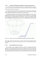
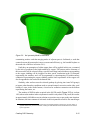
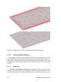
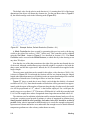
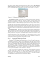
Figure 2-5
Meshing a Thin Solid (top) versus Meshing a Surface (bottom)
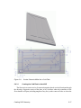
Therefore, TDMesh will be used instead to create a FEM model of the flange. A outer
rectangular region is subtracted from an inner rectangular region in AutoCAD, then meshed.
As experimentation will reveal, the mesher creates an even spacing of nodes on the inner
periphery of such a region, even if it’s not square, and even if the mesh resolution is increased,
etc. This fact means that coincident nodes are available to merge with those on the edges of
the FDM surfaces.
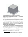
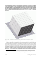
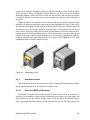
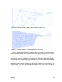
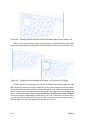
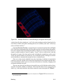
The finished model is depicted in Figure 2-6. The default mesher resolution results in
an 8x8 grid of element lengths along the insides of the flange region, with 9 nodes at the
endpoints of each equally-spaced segment. This means the side panels (represented by TD
FDM rectangles) can be chosen to use a node resolution of 9 using edge nodes, such that
the nodes along the inner periphery of the flange are coincident with the nodes at the bottom
edges of the side panels: they can be merged. Those “shared” nodes will participate both as
members of finite elements and as locations within a finite difference grid.8 The number of
nodes representing the height of the box need not be 9, as long as all sides use the same
Creating CAD Geometry
2-9