1
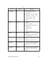
Figure 6-17
6.4
Option for Creating a 2D Symmetric Part When Extruding or Revolving
TDMesh Revolve
For meshing arbitrary solid CAD parts, TDMesh described in Section 6.2 is applicable.
However, many types of solids can be formed by revolving an arbitrary CAD surface around
an axis, with the mesh generated on that original surface also revolved along the arc.
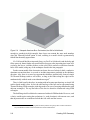
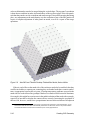
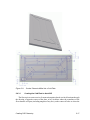
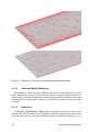
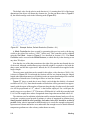
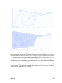
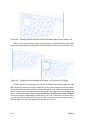
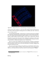
The resulting mesh is no longer a tri-tet mesh. Figure 6-18 shows a rectangle with three
holes (the red base part) that has been meshed in the original plane, then revolved 90 degrees
into six solid layers subtending 15 degrees each. The same triangular surface mesh exists
at all seven planes between these six solid layers, but the sides the surface elements are
quadrilaterals, and pentahedral elements (extruded triangles) are used for the solid portions
of the model.2
In addition to using higher-level finite elements, a revolved mesh has several important
advantages over a 3D tetrahedral mesh that would result if the full TDMesh had been applied
to the final (revolved) solid. All of these advantages relate to the fact that the key surfaces
in the resulting mesh can be addressed separately, which greatly facilitates application of
boundary conditions that vary according to the face. This capability is contrasted with that
of the full TDMesh, which can only generate and address all the surfaces as a single entity,
making no distinctions based on “faces” (which might not even exist, as in the example of
a sphere). In addition, revolving a base mesh can model the same solid geometry with less
elements than if it were meshed with tetrahedrons.
The usage of the TD Mesh Revolver is almost identical to that of the full TDMesh
explained in Section 6.2, so this section will only highlight important differences.
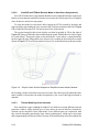
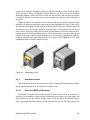
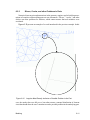
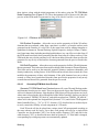
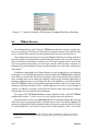
To use the mesh revolver, type tdmeshrevolve in the command prompt, then select an
AutoCAD region or appropriate surface, and then select an axis of revolution. Figure 6-15
shows the resulting form (which is identical to that of the mesh extruder described in Section
6.3). Note that the base, end, and side surfaces can be edited separately. “Base” refers to the
2 Revolving about an axis that touches one side of the part, or that is coincident with it, is legal. Such a revolution
results in some side surface elements that may not be quadrilaterals, and in some solid elements that may not be
pentahedrons.
6-20
Meshing