1
The Network Case Study
5 THE NETWORK CASE STUDY
In this chapter the distribution network under study is presented. This distribution network will be used to test and demonstrate the operation of the developed multi agent
system.
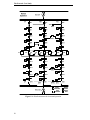
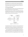
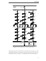
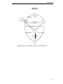
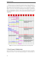
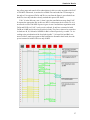
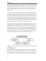
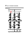
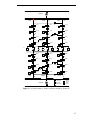
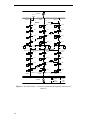
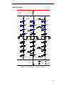
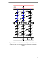
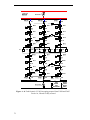
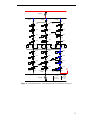
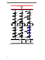
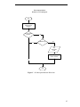
A diagram of the network is shown in Figure 4-1. In the system, power is provided
from two sources, Source1 and Source2, each through a distributed transformer. Each
transformer provides power to three feeders A, B and C, where each feeder includes
four buses each having a load attached. Switches are symbolized with a square symbol
in the diagram, where a black filling denotes that the switch is close while a white filling symbols an open switch.
All feeders are connected with each other making it possible to reconfigurate the
network in numerous ways. Each feeder is connected with the other feeders fed from the
same source through the switches denoted SAB, SBC and SAC. In addition, all feeders
are connected with feeders from the other source though the tie switches T1 –T9. On
each feeder every bus is separated by a switch, making it possible to isolate one or more
buses of the feeder if necessary. In normal operating conditions of the network all these
sectionalizing switches are closed, as shown in the figure.
Transmission lines impose constraints on how much power can be transmitted. For the
sake of simplicity each feeder has been assigned a maximum allowable MW flowing
through it. This will limit the amount of load which can be connected to the feeder in
addition to its own loads. How much a feeder can provide to another feeder then depends on its current load consumption. A power flow capacity of 500 MW will be used
for all feeders in the subsequent simulations.
As mentioned in chapter 2 it is desirable to keep a radial structure in the network during
restoration. This structure can be enforced whenever possible by assigning distances
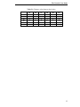
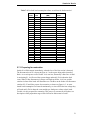
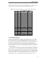
between the six feeders. The values used for the simulations can be seen in table 5-2.
Say that feeder 1A can be connected with one of the feeders 1B, 1C and 2A. Feeder 1A
should be connected to the feeder closest to it, which according to table 1A is feeder 1B,
with the distance 1. The feeder least desirable for feeder 1A to interconnected to is
feeder 2C with a distance of 5.
.
24