1
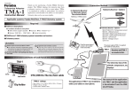
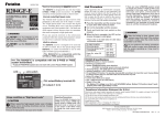
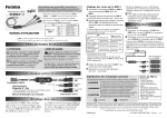
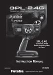
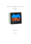
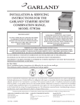
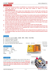
1M23N26714
Voltage sensor
SBS-01V
Instruction Manual
Thank you for purchasing Futaba's
SBS-01V Voltage Sensor. This sensor,
used in conjunction with a telemetry
enabled transmitter/receiver, is used to
indicate the voltage of the item to which
it is attached. Although the telemetry
receiver of Futaba's has a function
which measures voltage, if SBS-01V
is used, it can measure more battery
voltage. To maximize your enjoyment,
and to ensure proper sensing, please
read through this manual thoroughly.
We also encourage you to retain the
manual for future reference should the
need arise.
to EXT Battery
EXT Line
● The SBS-01V is designed for use with
Futaba telemetry systems.
Features
■ The SBS-01V will not function properly if connected to
an S.BUS port or other channel ports.
Measures receiver battery voltage
and the voltage of a second battery or
power supply.
External Line Range : 0-100V's
To ensure that the SBS-01V is functioning
as desired, please test accordingly. Weight : 0.2oz (6.0g)
■ Do not fly until inspection is complete.
Length : 34.25in (870mm)
Do not use the SBS-01V with anything
other than an R/C model.
In order to prevent any short circuits, please
observe the polarity of all connections.
■ Ensure that the unit is connected properly; failure to
do so could result in damage to the cable, receiver, etc.
Always mount the cable in accordance with
the instructions included in this manual.
Allow a slight amount of slack in the cable.
Normal Line
SBS-01V
3P Connector
Green/Red
Unrecoverable error
Alternate blink
Slot Number Setup
SBS-01V uses two continuous slots.
Please note that the proper default
start slot for this accessory is number
6. When setup-changing or adding,
it is the following numbers that are
made to a start slot.
1,2,3,4,5,6,8,9,10,11,12,13,14,16,17,
18,19,20,21,22,24,25,26,27,28,29,30
Information on how to change the
slot assignment is included in the
transmitter's manual.
Battery connection
What is measured is total voltage
when the battery which you want
to measure has two or more cells.
One cell of a battery with many cells
cannot be measured. Don't carry out
connection wiring at one cell. If it
connects with one cell, there is fear
of ignition.
Turn on the receiver prior to connecting the
Extra Voltage Input.
To prevent any short circuits, please ensure
that the cable is routed away from any conducive materials.
Don't apply voltage higher than 100V to Extra voltage line.
■ There is fear of explosion, ignition, and breakage.
S.BUS2 port
The example of wiring
LED Indication
Green/Red
■ If necessary, fasten this cable at a suitable location to
prevent any damage from vibration during flight.
It is cautious of the burn and fire in wiring
work enough.
The work of wiring must not connect a battery.
Heat Shrink Tube
Normal operation
No signal reception
When setting up the
slot
Ensure that the unit is connected properly
to the receiver. Failure to do so could result in
damage to the sensor.
Ensure that the unit is mounted in an area
that will eliminate exposure to fuel, water and
vibration.
■ As with any electronic components, proper
precautions are urged to prolong the life and increase
the performance of the SBS-01V.
Normal Line Range : 3.5-8.4V's
to
Green
Red
Failure to follow these safety precautions may result in
severe injury to yourself and others.
To utilize the SBS-01V altitude sensor,
connect it to the S.BUS2 port of the Futaba
telemetry enabled receivers. LED
Fuse(mount in either direction)
WARNING
Two drive batteries are measured (R7008SB use)
Drive battery 1
(EXT Battery)
to S.BUS2
port
Drive battery 2
(EXT Battery)
EXT Line
Normal Line
R7008SB
Receiver battery
●Battery voltage measurement for receivers [R7008SB use]
●The drive battery 1 is measured in an EXT port [R7008SB use]
●The drive battery 2 is measured in an EXT line [SBS-01V use]
Two drive batteries and power supplies for servos are measured (R7008SB use)
Drive battery 1
(EXT Battery)
Drive battery 2
(EXT Battery)
Power supplies
for servos
*SBS-01V measures two voltage. One corresponds to high voltages, such as a drive battery,
with an EXT line. Another is a normal line and is measurement of the battery for receivers of a
line connected to 3P connector, or the battery for servos.
EXT Line
Switch
Normal Line
to S.BUS2
port
Another power
supply Hub
R7008SB
Receiver battery
S.BUS2
servos
●Battery voltage measurement for receivers [R7008SB use]
●The drive battery 1 is measured in an EXT port [R7008SB use]
●The drive battery 2 is measured in an EXT line [SBS-01V use]
●The voltage for servos is measured in a power supply line [SBS-01V use]
The wiring processing method of an EXT Line
① Measure the cable and then cut it to the desired length.
cable
SBS-01V
② Cut approximately 30mm of the negative (-, black) line from the cable.
Solder the fuse inline on the negative wire and then reattach the section of wire
that was previously removed. The fuse should be attached as close to the
external power supply as possible.
Solder welding
The fuse should be attached as close to the
external power supply as possible.
Fuse to Black line (-)
Fuse(mount in either direction)
③ Place a piece of heat shrink tubing over the fuse, ensuring that it covers the
soldered areas. Shrink the tubing snug to the fuse and the wire using a heat gun.
Heat shrink tube
Heat shrink
Heat shrink tube
④ The cable should be connected as shown in the diagram below. The cable
gets connected to the wires that come off the ESC and connect to the battery.
To Receiver S.BUS2 port
Fuse
To Power Battery
motor
controller
To Motor
The connection is affixed to the ESC on the wires
that are connected to the battery by soldering them
and then protecting them with heat shrink.
⑤ The manual for the Telemetry system should be referred to after the setup is
complete; checking to make sure it functions as desired and that it provides the
correct voltage on the display.
FUTABA CORPORATION
1080 Yabutsuka, Chosei-mura, Chosei-gun, Chiba-ken, 299-4395, Japan
Phone: +81 475 32 6982, Facsimile: +81 475 32 6983
©FUTABA CORPORATION
2012, 10 (1)