1
The wiring processing method of an EXT Line
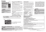
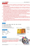
① Measure the cable and then cut it to the desired length.
cable
SBS-01V
② Cut approximately 30mm of the negative (-, black) line from the cable.
Solder the fuse inline on the negative wire and then reattach the section of wire
that was previously removed. The fuse should be attached as close to the
external power supply as possible.
Solder welding
The fuse should be attached as close to the
external power supply as possible.
Fuse to Black line (-)
Fuse(mount in either direction)
③ Place a piece of heat shrink tubing over the fuse, ensuring that it covers the
soldered areas. Shrink the tubing snug to the fuse and the wire using a heat gun.
Heat shrink tube
Heat shrink
Heat shrink tube
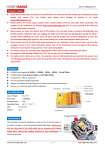
④ The cable should be connected as shown in the diagram below. The cable
gets connected to the wires that come off the ESC and connect to the battery.
To Receiver S.BUS2 port
Fuse
To Power Battery
motor
controller
To Motor
The connection is affixed to the ESC on the wires
that are connected to the battery by soldering them
and then protecting them with heat shrink.
⑤ The manual for the Telemetry system should be referred to after the setup is
complete; checking to make sure it functions as desired and that it provides the
correct voltage on the display.
FUTABA CORPORATION
1080 Yabutsuka, Chosei-mura, Chosei-gun, Chiba-ken, 299-4395, Japan
Phone: +81 475 32 6982, Facsimile: +81 475 32 6983
©FUTABA CORPORATION
2012, 10 (1)