1
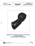
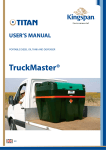
WWW.ANDYGUESTJETTERS.CO.UK
by
ANDY GUEST
JETTERS
OPERATOR’S MANUAL
V-PACK + COMPACK
SERIES OF HIGH PRESSURE JETTING EQUIPMENT
© Copyright April 2015, Andy Guest Jetters Ltd
Unit 11, Riparian Way
The Crossings Business Park
Cross Hills
Keighley
West Yorkshire, UK
BD20 7BW
Tel: +44 (0)3300 240404
Fax: +44 (0)1535 636969
Email: [email protected]
Web: www.andyguestjetters.co.uk
All rights reserved. No part of this publication may be copied or published by means of printing, photocopying,
microfilm or otherwise without the prior written consent of Andy Guest Jetters Ltd.
This restriction also serves in respect of all corresponding drawings and diagrams.
Andy Guest Jetters Ltd has the right to change components and assemblies at any time without prior or direct
correspondence with the operators. The contents of this manual may be changed without any prior warning.
This manual is to be used only for the equipment models stated.
For additional technical information or support please contact your local service agent which may be located
on the Company’s website.
TABLE OF CONTENTS
1.0INTRODUCTION
4
2.0
2.1
2.2
2.3
2.4
2.5
2.6
5
5
6
6
6
7
7
FUNCTIONALITY & GENERAL SAFETY
Equipment methodology
Safety Icons
Critical Safety Features
Personnel Protection Equipment (PPE)
General Warnings
Making Changes and Fabricating Non OEM Components
3.0 TECHNICAL SPECIFICATIONS
8
2.2 V-PACK Series
2.3 COMPACK Series
8
9
4.0CONSTRUCTION
10
4.1V-PACK
4.2COMPACK
10
11
5.0CONTROLS
12
5.1
5.2
5.3
5.4
5.5
5.6
5.7
5.8
5.9
5.10
5.11
5.12
5.13
5.14
12
12
12
13
13
13
13
13
14
14
14
14
15
15
Before Departure
Positioning the Vehicle
Hydraulic Reel Control
Engine Counter
Run Dry Protection (Optional)
Pre-Operational Checks
Starting the Engine
Using the Hard Wire Remote Control (Optional)
Using the Radio Remote Control (Optional)
Nozzle Application
Using Lances
Completion Procedures
Frost Protection
Recommended Maintenance Schedules
6.0TROUBLESHOOTING
16
6.1 Declarations & Directives
6.2 Useful Links & External References
16
17
7.0APPENDIX
18
7.1
7.2
18
20
Declarations & Directives
Service Centres
1.0INTRODUCTION
Foreword
This operator’s manual is designed for trained and competent users of industrial
jetting equipment as prescribed by the Water Jetting Association of the United
Kingdom. The purpose of the manual is to ensure safe and efficient operation of the
equipment with any associated drawings or images to serve as a guide only.
In each section we try to familiarise users with the most important safety aspects to
consider prior to the operation of the equipment along with the operating controls
and diagnosis of potential faults.
Andy Guest Jetters Ltd wishes to first thank you
for your purchase of our drain and sewer-clearing
equipment. We recommend that you read this
manual thoroughly to ensure that the equipment is
maintained and operated to the highest standard.
If you require technical support, additional parts
or services or indeed would like to schedule
an approved service – please don’t hesitate in
contacting us.
Other common uses for the equipment include the
cleaning and maintenance of walls, floors, building
materials and rubbish containers with cold or
warm water and can be used with our collection of
lances and accessories. If you aren’t sure about a
particular application you should always contact us
in the first instance for advice as no liability can be
placed on the company for consequential damage,
theft or injury to persons or property.
The machine is built by:
This manual contains all the necessary information
concerning control and maintenance. If the device
is installed correctly, properly controlled and
regularly maintained then the owner may invoke
a warranty claim for non-wear parts subject to the
terms of sale (which is normally 12 months from
date of invoice for new equipment and 3 months
on second hand purchases). Should, following
our investigation it be determined that the control
and maintenance procedures are not diligently
followed, the warranty will become invalid – this
does not affect your statutory rights.
Andy Guest Jetters Ltd
Unit 11, Riparian Way
The Crossings Business Park
Cross Hills
Keighley
West Yorkshire, UK
BD20 7BW
The equipment has been specifically designed
and manufactured for cleaning and unblocking
domestic and commercial drains in conjunction
with the uniquely calibrated high pressure jetting
nozzles that are supplied with your equipment
(other specialist nozzles are available for pipe
cleaning, silt removal, high fat content, other
foreign material based blockages and root cutting).
4
V-PACK + COMPACK Operator’s Manual
The machine may only be used by authorized
personnel and should not be operated in an explosive or hazardous environment. In this manual you
will find all necessary information concerning the
operation and maintenance of your machine.
2.0 FUNCTIONALITY & GENERAL SAFETY
2.1 Equipment Methodology
⊲⊲ 1 bar is equal to 14.5 psi
The integrated engine drives the high-pressure
pump using a V-belt. This pump receives water
from the water tank (which is usually filled via the
inlet reel), via the water filter before pressurisation
is applied to the desired level. The pressurised
water is ejected through the high-pressure hose
(black in colour and mounted on the HP reel)
and eventually passes through the high pressure
jetting nozzle.
⊲⊲ 1 UK gallon is equal to 4.55 litres
Many operators also purchase and install a three
metre “leader hose” which is normally blue in
colour. When retracting a hose that is in operation,
this tells the operator that they are nearing the end
of the line and so the pump should be turned off to
reduce the risk of high pressure water being
on operation outside of the confines of the
application, for example the sewer pipe. High
pressure water and an “out of control” nozzle
present one of the highest risks to health and
property when this equipment is in use.
Most machines are derived by the type and
power of the engine – normally between 20-55
horsepower (HP).
Typically the size of engine will determine the
size of pump however these can be varied in
accordance with the two principal factors of jetter
specification – pressure (velocity of water) and
flow (volume of water). These are normally quoted
in PSI (pounds per square inch) or BAR (derived
from the Greek word baros meaning weight with
1 bar being equal to atmospheric pressure)
and Gallons or Litres per minute – for example
3000@12 refers to 3000psi at 12 gpm and is
considered one of the most common specifications to deal with the largest volume of drain
blockages in the most efficient manner.
There are many types of engines and
pumps and many arrangements of equipment
resulting in different weights, sizes, serviceability
and performance. Our equipment has been
developed over time to provide a configuration
that we believe offers a high level of performance,
safety and reliability with low ownership costs.
Whilst the financial measure of the life of our
equipment tends to be governed by customer
accounting policies, the practical life of the
machine if properly maintained can be up to 20
years depending on usage. Typically we would
recommend replacement after 7-10 years when
performance begins to deteriorate and cost of
refurbishment is no longer viable to achieve
original performance parameters. There is a
market for used machines for which our brand of
equipment is still very desirable and as such we
would always recommend having second hand
equipment that hasn’t been refurbished by the
OEM (original equipment manufacturer) or a
recognised service agent – to be multi-point
checked prior to operation.
Other common accessories for safety and
efficiency include hard wired remote controls to
turn the water on and off when up to 100m away
from the operating vehicle, or radio/wireless
remote controls which can have the facility to
start/stop water, start/stop engine, retract the high
pressure hose reel or provide emergency stop
capabilities, depending on the number of channels
purchased and installed.
V-PACK + COMPACK Operator’s Manual
5
2.0 FUNCTIONALITY & GENERAL SAFETY
There are numerous accessories to provide
additional protection for people or equipment such
as safety lances that prevent a build-up of back
pressure to the machine, unloader valves which
return back pressurised water back to the tank
unlike the standard burst disc arrangement, run
dry switches that prevent pump operation if the
operator runs out of water, hose guidance adapter
so that operators don’t have to come into contact
with the high pressure hose when retracting from a
sewer line and many other additional yet optional
features.
As well as the general information in this chapter,
you should also follow the safety guidance in the
other chapters.
Always consider the safety of yourself and others
when operating this machine – try to complete
risk assessments before each job to highlight
potential hazards and either avoid and/or protect
people and equipment from their consequences.
2.2 Safety Icons
Any safety warnings in this manual that are
accompanied by the safety icon below (Security
sign DIN 4844-W9) are considered to present a
high level of danger to persons or equipment and
should be followed at all times.
DIN 4844-W9
This machine is equipped with an emergency stop.
By operating the emergency stop, the machine will
stop immediately. Do not use this button for normal
operation and only use it in emergencies. The stop
button will remain depressed after application so
that the equipment cannot be restarted.
If used, and only when the danger has been
averted, twist/pull the emergency stop button back
out in order to be able to use the equipment again.
Ensure the emergency stop is always accessible.
Security Covers
This machine is equipped with several safety
covers designed to protect users from rotating
parts or hot surfaces. Do not remove these
security covers.
2.4 Personnel protection
equipment (PPE)
The following PPE is prescribed when operating
the equipment:
⊲⊲ Ear protection (LWA 109dB)
⊲⊲ Eye protection
⊲⊲ Hand Protection (gloves)
⊲⊲ Waterproof clothing
⊲⊲ Spray boots with toe protection
2.3 Critical Safety Features
6
Emergency Stop
V-PACK + COMPACK Operator’s Manual
Always apply PPE prior to operation of the
equipment and use your risk assessments to
determine if additional PPE is required.
2.5 General Warnings
From our experience of commonly reported
incidents and near misses, please take note of the
following:
⊲⊲ Never operate the equipment near a person
or animal
⊲⊲ Use protective barriers to reduce the risk of
unauthorised access to the work area
⊲⊲ Never block the control levers in any way or
lean equipment on or near them
⊲⊲ Ensure that the high pressure nozzle does not
leave the drain whilst the unit is in operation
⊲⊲ Before using a spray gun, you must always set
the pressure below the maximum (± the half
of the maximum pressure is recommended)
and this should be done before the machine is
started
If the safety guidance is not observed you increase
the risk of near-misses and serious accidents.
Always try to recognise the important functions
and controls, ensure you follow maintenance and
pre-check recommendations and most importantly
remember that no job is worth risking the safety of
yourself and others.
2.6 Making Changes
and Fabricating Non
OEM Components
Changes to the machine will affect your warranty
and may result in significant rectification costs
or potential safety hazards and therefore should
only be conducted if authorised in writing and in
advance by an authorised representative of Andy
Guest Jetters Ltd.
⊲⊲ Never exceed the maximum pressure that is
marked on the manometer when using the
spray gun
⊲⊲ After use of the high-pressure circuit ensure
that you depressurise it
⊲⊲ Always check for electrical feeds or equipment
if you are cleaning with a spray gun
⊲⊲ Always check for loose items near the application of the spray gun to avoid them becoming
projectiles
⊲⊲ Personnel that use, maintain and inspect the
equipment should be suitably qualified and
authorised.
V-PACK + COMPACK Operator’s Manual
7
3.0 TECHNICAL SPECIFICATIONS
V-PACK SERIES
Machine Model/Type
2 Series Stack
2 Series
3 Series
4 Series
Std Water Tank Capacity
210 Litres
210 Litres
400 Litres
400 Litres
Frame Construction
Compact mild steel construction, shot blasted, zinc primed & powder coated
Engine
Kohler V Twin Diesel 3 Cylinder Diesel
Lombardini LDW1404
Lombardini LDW2204
Engine Power
20HP (14kW)
33HP (24kW)
44HP (32kW)
20HP (14kW)
Hours Run Time Monitor
Engine Based
HP Pump Type
Interpump
Interpump
Speck NP
Speck P
Capacity
3000PSI / 8GPM
3000PSI / 9GPM
3000PSI / 12GPM
3625PSI / 13GPM
(Others Available)
200Bar / 38LPM
200Bar / 40LPM
200Bar / 54LPM
250Bar / 60LPM
Engine Cooling
Air Cooled
Water Cooled
Water Cooled
Water Cooled
Run Dry Protection
Optional
Frost Protection
Anti Freeze Valve
Hydraulic Drive HP
Hydraulic
Hose Guidance
Optional
High Pressure
Hose Length
45 Metres ½” Std
90 Metres ½” Std
90 Metres ½” Std
Fixed Reel
Hose Reel Arrangement
Filling Hose
90 Metres ½” Std
Optional
Optional
25 Metres
25 Metres
Yes
Control Box
5 Channel (Optional)
Remote Control
2 Standard Nozzles ~ User Manual ~ back pressure safety burst disc
Included Accessories
Approx Dry Weight*
360 KG
360 KG
455 KG
565 KG
Approx Max Weight*
570 KG
570 KG
855 KG
965 KG
1250 x 1200 x 1200
1350 x 1300 x 1350
1350 x 1350 x 1350
*with standard tank
*with standard tank
*with standard tank
20 Litres
20 Litres
30 Litres
Machine Dimensions
(Mm) (Length, Width, Height)*
Fuel Tank Capacity
TBC
20 Litres
Upgradeable
8
V-PACK + COMPACK Operator’s Manual
YES
COMPACK SERIES
Machine Model/Type
3 Series
4 Series
5 Series
Std Water Tank Capacity
400 Litres
400 Litres
400 Litres
Frame Construction
Compact Lightweight aluminium construction, self colour option
Engine
Lombardini LDW1404
Lombardini LDW2204
Lombardini LC
Engine Power
33HP (24kW)
44HP (32kW)
50HP (37kW)
Hours Run Time Monitor
Engine Based
HP Pump Type
Speck NP
Speck P
Speck P
Capacity
3000PSI / 12GPM
3625PSI / 13GPM
4000PSI / 13GPM
(Others Available)
200Bar / 54LPM
250Bar / 60LPM
275 Bar / 60LPM
Engine Cooling
Water Cooled
Water Cooled
Water Cooled
Run Dry Protection
Optional
Frost Protection
Anti Freeze Valve
Hydraulic Drive HP
Hydraulic
Hose Guidance
High Pressure
Hose Length
Yes
80 Metres ½” NW13
(LightWeight)
80 Metres ½” NW13
(LightWeight)
Hose Reel Arrangement
Fixed Reel
Filling Hose
25 Metres
Control Box
Yes
Remote Control
100 Metres ¾” NW19
(LightWeight)
5 Channel (Optional)
Included Accessories
2 Standard Nozzles ~ User Manual ~ back pressure safety burst disc
Approx Dry Weight*
420 KG
530 KG
535 KG
Approx Max Weight*
820 KG
930 KG
935 KG
Machine Dimensions
1100 x 1200 x 950
1350 x 1350 x 1050
1350 x 1350 x 1050
(Mm) (Length, Width, Height)*
*with standard tank
*with standard tank
*with standard tank
Fuel Tank Capacity
20 Litres
30 Litres
30 Litres
Upgradeable
YES
V-PACK + COMPACK Operator’s Manual
9
4.0CONSTRUCTION
4.1V-PACK
05
04
03
01
09
07
15
06
08
18
14 02 19
17
11
10
20
21
13
12
01
High Pressure Hose & Reel
12
Anti-freeze suction pipe
02
Overflow pipe
13
Selector Valve
03
Water tank
14
Pump
04
Supply opening water tank
15
Hose guidance adapter
05
Inlet hose on reel
16
Drain
06
Hydraulic reel control
17
Hydraulic Oil tank
07
Throttle
18
Fuel tank with opening
08
Control box
19
Anti-freeze valve
09
Rotary joint
20
Hardwire remote socket
10
Pressure gauge
21
Emergency Stop
11
Water filter
10
V-PACK + COMPACK Operator’s Manual
16
4.2COMPACK
08
11
10
12
19
04
15
09
13
01 02 03
06
14
07
1
Low water override switch
9
Acoustic cover lock - female
2
Radio remote control switch
10
Acoustic cover support
3
Emergency stop (Also on V-Pack frame)
11
Inlet reel rotary joint
4
Leader hose
12
Selector valve
5
Drain & Anti-freeze valve
13
Fuel level sight gauge
6
Hydraulic reel control
14
Throttle
7
Water filter
15
Water Tank Flow Valve
8
Acoustic cover lock - male
V-PACK + COMPACK Operator’s Manual
05
11
5.0CONTROLS
Note: all controls and their operation will be
clearly labelled on all new equipment.
5.1 Before Departure
Before you drive away, check the following:
⊲⊲ Roll the HP-hose neatly and fully onto the hose
reel ensuring no kinks
⊲⊲ Ensure the Hydraulic Reel Control is NOT in the
“Free Wheel” position
⊲⊲ Roll the inlet hose neatly and fully onto the
hose reel ensuring no kinks
⊲⊲ Ensure the water tank has been drained to
approximately 10% capacity before driving
5.2 Positioning The Vehicle
When positioning the vehicle please take note of
the following:
⊲⊲ Vehicle engine turned off, vehicle in gear and
hand brake applied
⊲⊲ Always try to site the vehicle on a level, hard
standing
⊲⊲ See to it that the vehicle is more or less level.
⊲⊲ If parked on a hill your fuel may run out faster
than usual if the liquid gathers away from the
suction end
⊲⊲ Secure the working area according the local
regulations
⊲⊲ Activate all appropriate hazard and work lights
and beacons
5.3 Hydraulic Reel Control
There are three settings for this control:
⊲ IN ⊲ OUT ⊲ FREE WHEEL
In “FREE WHEEL” mode the reel can be manually
operated either in or out. When the lever is
12
V-PACK + COMPACK Operator’s Manual
positioned “OUT” the hydraulic motor will feed
out the high pressure hose. When the lever is
positioned “IN” the hydraulic motor will pull the
high pressure hose back on to the reel. You can
control the speed at which the hydraulic motor
operates by adjusting the throttle lever.
When operating the hydraulic reel control please
take note of the following:
⊲⊲ The hose should remain pressurised when
retracting until only 3 metres of hose remain in
the drain or immediately upon sight of sight of
the leader hose (optional) – this reduces the
risk of the hose stretching or becoming
compacted on the hose reel which upon
re-pressurisation can cause damage to the
hose and reel – always remove the jetting
nozzle from the HP hose after use
⊲⊲ Do not let the unit run out of water prior to
retraction, if this happens and you cannot find
a local source of water, you should retract the
hose manually and then when possible let out
all hose, safely pressurise before hydraulic
retraction is performed
⊲⊲ Always retract the hose slowly to ensure it is
neatly rolled onto the reel, keep hands and
clothing away from the reel to avoid crushing
and always check for contaminants or sharps
that may have lodged onto the reel (an optional
hose reel guide is available to eliminate direct
hand contact with the hose)
⊲⊲ It is good practice to check the condition of
the hose during retraction and if you suspect
any damage to the hose you should have it
replaced by an authorised agent immediately
5.4 Engine Counter
5.7 Starting The Engine
All engines are equipped with a visual hours
counter. This indicates the total number of hours
that the engine has been operated and can be
used to determine when the unit is ready for
maintenance and servicing.
To start the engine please ensure the following:
5.5 Run Dry Protection
(Optional)
⊲⊲ If you have a radio remote, ensure the switch is
set to manual
Some units are equipped with a run dry switch
so that when the tank water level reaches approximately 5-10% the engine will automatically turn off,
furthermore an override switch can also be added
so that in the event that the run dry switch activates, the operator may still briefly use the engine
to activate other functions such as the hydraulic
reel control or the anti-freeze suction valve.
5.6 Pre-Operational Checks
You should check the following prior to operation:
⊲⊲ Engine Oil
⊲⊲ Hydraulic Oil
⊲⊲ Pump Oil
⊲⊲ Fuel Level
⊲⊲ Water Level in main tank (maximum recommended water temperature is 60oc / 140of
⊲⊲ Water filter should be clean and free of debris
⊲⊲ Check nozzle holes and clear debris before
attaching nozzle to the high pressure hose
⊲⊲ Connect the inlet hose to your supply feed and
turn on OR put a supply hose directly into the
water tank by removing the filler cap
⊲⊲ Ensure you are in a position to operate the
equipment safely
⊲⊲ Ensure the emergency stop button is in the
open position
⊲⊲ Insert the key and turn it to ignition holding until
the glow plug light switches off and then start
the engine
⊲⊲ If everything is running correctly, you will see a
green light appear on the control panel
⊲⊲ If you receive any warning lights, please consult
your engine booklet supplied with the new
equipment or contact one of the service centres
5.8 Using the Hard Wire
Remote Control (Optional)
If you have purchased a hard wire remote control,
you will receive a foot pedal and the requested
amount of cabling (normally 80-100m). Plug your
foot pedal connector into the hardwire remote
socket prior to starting the engine – determine the
pressure you require using the throttle and then
apply the foot switch in order to turn water on via
the pump. As soon as you release pressure from
the foot switch, the water will stop.
⊲⊲ DO NOT switch of the engine with the foot
pedal still depressed as this will result in
pressurised water the next time the machine is
turned on without the foot pedal connected. If
you have done this inadvertently, remove the
nozzle from the high pressure hose, position
the hose to the ground or into a drain, plug in
your foot pedal and start the engine – this will
return the water to the off position
V-PACK + COMPACK Operator’s Manual
13
5.0CONTROLS
5.9 Using The Radio
Remote Control (Optional)
5.11 Using Lances
If you have purchased a radio remote control, you
should have had the receiver kit installed to your
nominated vehicle by a qualified professional and
have also received a remote handset. These will
typically provide the following operations:-
⊲⊲ Dry Shut
⊲⊲ Remote On/Off
⊲⊲ Throttle Up/Down
⊲⊲ Water On/Off
⊲⊲ Emergency Stop
Before starting the engine, switch the radio remote
switch to “Radio Remote”, turn the ignition on and
hold the corresponding “on” buttons down at the
same time to turn on the remote – now start the
engine.
5.10 Nozzle Application
The high pressure nozzles are designed to use
the hydraulic pressure to pull the hose through
the sewer pipe and depending on application
and nozzle, a degree of cleaning or unblocking will commence immediately. All nozzles will
have the capability to eject water in a backwards
direction to project them forward and others will
also include forward ejecting water to assist in
the clearance of blockages and debris. The basic
principal can be seen below:
There are two types of lance:
⊲⊲ Safety or Unloader
If you are using a dry shut lance, you should
ensure that you have an unloader valve fitted to
your jetting equipment in lieu of a burst disc arrangement. The most common cause of burst disc
failure (a manufactured weak spot to protect from
backpressure) is when using lances. An unloader
valve (or pressure relief valve) is designed to return water back to the water tank in the event that
the back pressure exceeds the desired level.
A safety lance or unloader lance has the valve
incorporated in its design so that any back pressure will eject from the lance, normally through a
secondary barrel pointing in the same direction as
the pressurised water.
You should always check that the working pressure on the lance corresponds with the pressure
of the machine and start the unit on the lowest
pressure setting and when in operation, increase
slowly to the correct working pressure. After use
and when the engine is turned off, activate the
trigger to release pressure from the hose.
5.12 Completion Procedures
At the end of the job, you should:
⊲⊲ Retract the HP hose and secure
⊲⊲ Remove nozzle from hose and store on frame
bracket if applicable
⊲⊲ Retract the Inlet hose and secure
⊲⊲ Stop the engine, store any accessories and
drain the water tank down to approximately
5-10% capacity
14
V-PACK + COMPACK Operator’s Manual
5.13 Frost Protection
It is important to protect your equipment, particularly the high pressure pump from freezing as this
can damage your equipment. You should never
attempt to run your equipment if you suspect it
has frozen. Many customers will install a night
heater (optional) for cold weather periods though
all equipment is fitted with an anti-freeze valve as
standard. We recommend during cold weather that
you either perform the anti-freeze procedure at the
end of the day when the unit is no longer going to
be used or prior to any long journeys.
The following procedure should be applied:
⊲⊲ Drain water tank
⊲⊲ Turn anti-freeze valve to the open position
(pointing towards the anti-freeze pipe)
⊲⊲ Put pressure hose into anti-freeze drum
(ensure no nozzles are attached)
⊲⊲ Start engine and run until water starts running
clear or drum has been filled to original level
Obviously the process will have a slight diluting effect so care must be taken and it is only designed
to reduce the risk of freezing so normal safety
checks should always be conducted.
5.14Recommended
Maintenance Schedules
We would recommend the following maintenance
plans conducted by a recognised service agent
using only OEM parts.
ACTION
FREQUENCY
Check oil levels
Daily
Clean water filter
Daily or after high concentration of pollutants
Service engine
⊲⊲ Start engine and run until anti-freeze comes out
of high pressure hose (ensure no nozzles are
attached)
Every 250 working hours
or 6 monthly – whichever
soonest
Lubricate moving parts
Every 250 working hours
or 6 monthly – whichever
soonest
⊲⊲ Turn selector valve to dump and turn the remote briefly onto pressure (remote only)
Cleaning pressure
regulator
Every 250 working hours
or 6 monthly – whichever
soonest
Renew pump oil
Every 500 working hours
or annually – whichever
soonest
⊲⊲ Turn the water tank flow valve to the closed
(vertical) position (COMPACK ONLY)
⊲⊲ Put anti-freeze hose into the anti-freeze drum
⊲⊲ Turn selector valve to pressure
⊲⊲ Turn remote off and stop engine
***Do not run the equipment with selector in dump
position and remote off or all anti-freeze will be
dumped back into the tank
Renew oil hydraulic
system
START-UP
Decalcify suction valves
Annually
(post anti-freeze > pre-operation)
Decalcify pressure valves
Annually
⊲⊲ Refill water tank
Re-puncture nozzle holes
Every 50 working hours
⊲⊲ Turn anti-freeze valve and water tank flow valve
(if applicable) back to original operating position
V-PACK + COMPACK Operator’s Manual
15
6.0TROUBLESHOOTING
6.1 Troubleshooting Guide
Failure
Engine does not start or
stops abruptly
The high-pressure pump
does not produce the
required pressure.
Pressure not consistent
16
Reason
Solution
Machine has run out of fuel
Add fuel
Main or secondary fuse blown
Contact your service agent
Battery voltage too low
Charge or replace
Emergency stop activated
Release the emergency stop on machine/
remote
Water tank empty
Fill the water tank
Water tank flow valve closed
Open the valve
Water filter clogged
Stop the machine and clean the water filter
Air in high-pressure pump
Allow the machine to run for a few minutes
and if the air doesn’t bleed out contact your
service agent
Suction valves blocked
Carefully loosen the valves and descale
them
Pump drive belt not sufficiently tightened
Tighten the belt; replace if necessary
Suction valves worn out
Contact your service agent
Water level in tank too low
Stop the engine, refill the tank and restart
engine
Water supply valve not sufficiently opened
Open the supply valve completely
Water filter clogged
Stop the machine and clean the filter
Pump sucks air
Stop the machine and check all hoses and
couplings for leakage
Nozzle clogged
Stop the machine and clean the nozzle
(clean the nozzle holes)
Pressure valves dirty or worn
Stop the machine. Check the condition of
the pressure valves. Clean or replace them
Pump packing’s worn out
Stop the machine and replace gasket
Pump drive belts slipping
Stop the machine and tighten the belts
Pump plungers damaged
Contact your service agent
Pressure control clogged or damaged
Contact your service agent
V-PACK + COMPACK Operator’s Manual
Failure
Hydraulic reel does not
wind the hose
Warning lights after short
operation
Reason
Solution
Handle not on correct position
Put the handle into the correct position
Hydraulic tank almost empty
Refill the tank. Check the system for leaks
Working pressure set too low
Increase the working pressure, if possible
Return filter for hydraulic tank dirty
Switch off the machine and clean the return
filter
Hydraulic system damaged
Contact your service agent
Recharge or replace battery
Battery flat / defective
Check if the unit is charging correctly
Check battery terminals for debris
Electrical supply
appears fine but equipment not functioning
Emergency stop pushed in
Unlock emergency stop
Receiver has no current
Check / replace fuses
No radio connection
Check functions of control lights
6.2 Useful Links & External References
⊲⊲ www.lombardini.co.uk
⊲⊲ www.speck.co.uk
⊲⊲ www.interpump.co.uk
⊲⊲ www.waterjetting.org.uk
⊲⊲ www.draintraderltd.com
V-PACK + COMPACK Operator’s Manual
17
7.0APPENDIX
7.1 Declarations & Directives
EC Declaration of Conformity for Machinery
(Directive 2006/42/EC, Annex II, sub A) Andy Guest Jetters Ltd
Unit 11, Riparian Way
The Crossings Business Park
Cross Hills
Keighley
West Yorkshire, UK
BD20 7BW
Herewith declares that:
High pressure device models V-PACK & COMPACK are
⊲⊲ in compliance with the Machinery Directive (2006/42/EC);
⊲⊲ in conformity with the provisions of the following other EEC directives: 2004/108/EC
⊲⊲ and the following harmonised standards have been applied:
NEN-EN-ISO 12100-1, NEN-EN-ISO 12100-2, NEN-EN-ISO 13850,
NEN-EN-ISO 13857, NEN-EN-349, EN 60204-1
Mr James Michael Burke
UK General Manager
On Behalf of:
Rioned UK Ltd & Andy Guest Jetters Ltd
18
V-Pack + COMPACK Operator’s Manual
Manufacturing
Sales + Service
Andy Guest Jetters Ltd
Rioned UK Ltd
Unit 11, Riparian Way
23 James Carter Road
The Crossings Business Park
Mildenhall
Cross Hills, Keighley
Suffolk, IP28 7DE
West Yorkshire BD20 7BW
United Kingdom
T +44 (0)3300 240404
T +44 (0)3300 240404
F +44 (0)1535 636969
F +44 (0) 1638 716863
www.andyguestjetters.co.uk
www.rioned.co.uk
[email protected]
[email protected]
Service Agents
Crumlin Plant Sales Limited
Midland Jetting Services Ltd
90a Blackisland Road
Unit 4 Kingfisher Ind Estate
Craigavon
Charles Street
Portadown BT62 1NH
West Bromwich
Tel: 0283 885 2540
West Midlands B70 0AT
HP Pump Services
Tel: 0121 520 6641
Wynford Industrial Park
N1 Jetting Systems Limited
Romsey
Unit 13 Cathedral Park
Hampshire, SO51 0PW
Durham DH1 1TF
01794 367 477
Tel: 0191 375 7779
Hydro Power UK Ltd
Scotjet Limited
Unit 19d Robell Way
50 Loanbank Quadrant
Water Lane Industrial Estate
Glasgow
Storrington (Nr. Pulborough)
Lanarkshire G51 3HZ
West Sussex RH20 3DW
Tel: 0141 440 0200
Tel: 01903 741780
Kensway Engineering
Unit 5 Dotton Farm
Sidmouth
Devon EX10 0JY
Tel: 0139 556 7374
www.andyguestjetters.co.uk
[email protected]