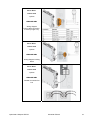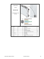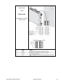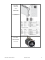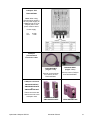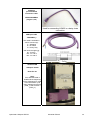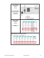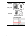
1
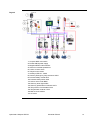
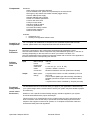
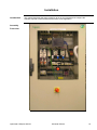
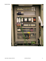
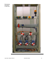
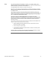
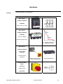
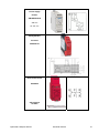
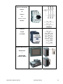
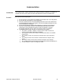
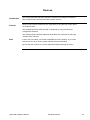
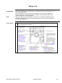
This document is based on European standards and is not valid for use in U.S.A.
Compact / CANopen /
HMI Controller / XBT GC/GT/GK
EIO0000000288.01
System User Guide
FEB 2011
Contents
Important Information.................................................................................................................3
Before You Begin..................................................................................................................4
Introduction .................................................................................................................................6
Abbreviations........................................................................................................................7
Glossary ................................................................................................................................8
Application Source Code .....................................................................................................9
Typical Applications...........................................................................................................10
System .......................................................................................................................................12
Architecture.........................................................................................................................12
Installation...........................................................................................................................16
Hardware ..........................................................................................................................................................20
Software ...........................................................................................................................................................35
Communication ...............................................................................................................................................36
Implementation ...................................................................................................................45
Communication ...............................................................................................................................................48
Controller .........................................................................................................................................................49
HMI....................................................................................................................................................................80
Devices.............................................................................................................................................................87
Altivar 312 ...................................................................................................................................................88
Lexium 32A .................................................................................................................................................90
TeSysU ........................................................................................................................................................92
Advantys OTB ............................................................................................................................................94
Appendix....................................................................................................................................97
Detailed Component List ...................................................................................................97
Component Protection Classes.......................................................................................100
Environmental Characteristics ........................................................................................100
Component Features........................................................................................................101
Contact.....................................................................................................................................109
Optimized CANopen XBTGC
Schneider Electric
2
Important Information
NOTICE
Read these instructions carefully, and look at the equipment to become familiar with
the device before trying to install, operate, or maintain it. The following special
messages may appear throughout this documentation or on the equipment to warn of
potential hazards or to call attention to information that clarifies or simplifies a
procedure.
The addition of this symbol to a Danger or Warning safety label indicates that an
electrical hazard exists, which will result in personal injury if the instructions are not
followed.
This is the safety alert symbol. It is used to alert you to potential personal injury
hazards. Obey all safety messages that follow this symbol to avoid possible injury or
death.
DANGER
DANGER indicates an imminently hazardous situation, which, if not avoided, will result in
death or serious injury.
WARNING
WARNING indicates a potentially hazardous situation, which, if not avoided, can result in
death, serious injury, or equipment damage.
CAUTION
CAUTION indicates a potentially hazardous situation, which, if not avoided, can result in
injury or equipment damage.
CAUTION
CAUTION indicates a potentially hazardous situation, which, if not avoided, can result in
injury or equipment damage.
PLEASE Electrical equipment should be installed, operated, serviced, and maintained only by
qualified personnel. No responsibility is assumed by Schneider Electric for any
NOTE
consequences arising out of the use of this material.
A qualified person is one who has skills and knowledge related to the construction
and operation of electrical equipment and the installation, and has received safety
training to recognize and avoid the hazards involved
© 2008 Schneider Electric. All Rights Reserved.
Optimized CANopen XBTGC
Schneider Electric
3
Before You Begin
Do not use this product on machinery lacking effective point-of-operation guarding. Lack of effective point-ofoperation guarding on a machine can result in serious injury to the operator of that machine.
WARNING
UNGUARDED MACHINERY CAN CAUSE SERIOUS INJURY
• Do not use this software and related automation products on equipment which does not have
point-of-operation protection.
• Do not reach into machine during operation.
Failure to follow these instructions can cause death, serious injury or equipment
damage.
This automation equipment and related software is used to control a variety of industrial processes. The type or
model of automation equipment suitable for each application will vary depending on factors such as the control
function required, degree of protection required, production methods, unusual conditions, government regulations,
etc. In some applications, more than one processor may be required, as when backup redundancy is needed.
Only the user can be aware of all the conditions and factors present during setup, operation and maintenance of
the machine; therefore, only the user can determine the automation equipment and the related safeties and
interlocks which can be properly used. When selecting automation and control equipment and related software for
a particular application, the user should refer to the applicable local and national standards and regulations. A
“National Safety Council’s” Accident Prevention Manual also provides much useful information.
In some applications, such as packaging machinery, additional operator protection such as point-of-operation
guarding must be provided. This is necessary if the operator’s hands and other parts of the body are free to enter
the pinch points or other hazardous areas and serious injury can occur. Software products by itself cannot protect
an operator from injury. For this reason the software cannot be substituted for or take the place of point-ofoperation protection.
Ensure that appropriate safeties and mechanical/electrical interlocks for point-of-operation protection have been
installed and are operational before placing the equipment into service. All mechanical/electrical interlocks and
safeties for point-of-operation protection must be coordinated with the related automation equipment and software
programming.
NOTE: Coordination of safeties and mechanical/electrical interlocks for point-of-operation protection is
outside the scope of this document.
START UP AND TEST
Before using electrical control and automation equipment for regular operation after installation, the system should
be given a start up test by qualified personnel to verify correct operation of the equipment. It is important that
arrangements for such a check be made and that enough time is allowed to perform complete and satisfactory
testing.
Optimized CANopen XBTGC
Schneider Electric
4
CAUTION
EQUIPMENT OPERATION HAZARD
• Verify that all installation and set up procedures have been completed.
• Before operational tests are performed, remove all blocks or other temporary holding means
used for shipment from all component devices.
• Remove tools, meters and debris from equipment.
Failure to follow these instructions can result in injury or equipment damage.
Follow all start up tests recommended in the equipment documentation. Store all equipment documentation for
future reference.
Software testing must be done in both simulated and real environments.
Verify that the completed system is free from all short circuits and grounds, except those grounds installed
according to local regulations (according to the National Electrical Code in the U.S.A, for instance). If high-potential
voltage testing is necessary, follow recommendations in equipment documentation to prevent accidental
equipment damage.
Before energizing equipment:
• Remove tools, meters, and debris from equipment.
• Close the equipment enclosure door.
• Remove ground from incoming power lines.
• Perform all start-up tests recommended by the manufacturer.
OPERATION AND ADJUSTMENTS
The following precautions are from NEMA Standards Publication ICS 7.1-1995 (English version prevails):
• Regardless of the care exercised in the design and manufacture of equipment or in the selection and rating of
components, there are hazards that can be encountered if such equipment is improperly operated.
It is sometimes possible to misadjust the equipment and thus produce unsatisfactory or unsafe operation. Always
use the manufacturer’s instructions as a guide for functional adjustments. Personnel who have access to these
adjustments should be familiar with the equipment manufacturer’s instructions and the machinery used with the
electrical equipment.
• Only those operational adjustments actually required by the operator should be accessible to the operator. Access
to other controls should be restricted to prevent unauthorized changes in operating characteristics.
WARNING
UNINTENDED EQUIPMENT OPERATION
• Only use software tools approved by Schneider Electric for use with this equipment.
• Update your application program every time you change the physical hardware configuration.
Failure to follow these instructions can cause death, serious injury or equipment
damage.
Optimized CANopen XBTGC
Schneider Electric
5
Introduction
Introduction
This document is intended to provide a quick introduction to the described system. It is not
intended to replace any specific product documentation, nor any of your own design
documentation. On the contrary, it offers additional information to the product
documentation, for installing, configuring and implementing the system.
The architecture described in this document is not a specific product in the normal
commercial sense. It describes an example of how Schneider Electric and third-party
components may be integrated to fulfill an industrial application.
A detailed functional description or the specification for a specific user application is not
part of this document. Nevertheless, the document outlines some typical applications
where the system might be implemented.
The architecture described in this document has been fully tested in our laboratories using
all the specific references you will find in the component list near the end of this document.
Of course, your specific application requirements may be different and will require
additional and/or different components. In this case, you will have to adapt the information
provided in this document to your particular needs. To do so, you will need to consult the
specific product documentation of the components that you are substituting in this
architecture. Pay particular attention in conforming to any safety information, different
electrical requirements and normative standards that would apply to your adaptation.
It should be noted that there are some major components in the architecture described in
this document that cannot be substituted without completely invalidating the architecture,
descriptions, instructions, wiring diagrams and compatibility between the various software
and hardware components specified herein. You must be aware of the consequences of
component substitution in the architecture described in this document as substitutions may
impair the compatibility and interoperability of software and hardware.
Optimized CANopen XBTGC
Schneider Electric
6
Abbreviations
Abbreviation
AC
CB
CFC
DI
DO
DC
DFB
EDS
E-STOP
FBD
HMI
I/O
IL
IP
LD
MBTCP
MFB
PC
POU
PDO
PS
RMS
RPM
RTU
RPDO
SD
SE
SFC
SDO
ST
TPDO
TVDA
UDP
VSD
WxHxD
Optimized CANopen XBTGC
Signification
Alternating Current
Circuit Breaker
Continuous Function Chart - a programming language based on
function chart
Digital Input
Digital Output
Direct Current
Derived Function Blocks
Electronic Data Sheet
Emergency Stop
Function Block Diagram - an IEC-61131 programming language
Human Machine Interface
Input/Output
Instruction List - a textual IEC-61131 programming language
Internet Protocol
Ladder Diagram - a graphic IEC-61131 programming language
Communications protocol with Modbus over TCP (Ethernet)
PLCopen Motion Function Block
Personal Computer
Programmable Object Unit, Program Section in SoMachine
Process Data Object (CANopen)
Power Supply
Root Mean Square
Revolution Per Minutes
Remote Terminal Unit
Receive Process Data Object (CANopen)
Stepper motor Drive
Schneider Electric
Sequential Function Chart - an IEC-61131 programming language
Service Data Object
Structured Text - an IEC-61131 programming language
Transmit Process Data Object (CANopen)
Tested, Validated and Documented Architecture
User Data Protocol
Variable Speed Drive
Dimensions: Width, Height and Depth
Schneider Electric
7
Glossary
Expression
Advantys
Advantys Configuration
Software
Altivar (ATV)
CANopen
Harmony
Lexium (LXM)
Magelis
Magelis XBTGC HMI
controller
Phaseo
PLCopen
Preventa
SoMachine
TeSys
Vijeo Designer
Optimized CANopen XBTGC
Signification
SE product name for a family of I/O modules
SE software product to parameterize the Advantys I/O modules
SE product name for a family of VSDs
Name for a communications machine bus system
SE product name for a family of switches and indicators
SE product name for a family of servo drives
SE product name for a family of HMI devices
SE product name for a HMI controller
SE product name for a family of power supplies
An international standard for industrial controller programming.
SE product name for a family of safety devices
SE product name for an integrated software tool
SE product name for a family of motor protection devices and
load contactors
SE product name for Magelis HMI devices configuration software
Schneider Electric
8
Application Source Code
Introduction
The example source code is in the form of configuration, application and import files. Use the
appropriate software tool to either open or import the files.
Extension
CSV
DCF
DOC
DWG
EDS
PDF
PROJECT
VDZ
ZW1
Optimized CANopen XBTGC
File Type
Comma Separated Values, Spreadsheet
Device Configuration File
Document file
Project file
Electronic Data Sheet - Device Definition
Portable Document Format - document
Project file
Project file
Project archive file
Schneider Electric
Software Tool Required
MS Excel
Advantys Configuration Software
Microsoft Word
AutoCAD
Industrial standard
Adobe Acrobat
SoMachine
Vijeo Designer
EPLAN P8
9
Typical Applications
Introduction
Here you will find a list of the typical applications, and their market segments, where
this system or subsystem can be applied:
Packaging
• Filling & closing machines
• Boxing machines
• Carton closing / erecting machines
• Shrink wrapping machines
Textile
•
•
•
•
•
•
•
•
Opening and closing machines
Circular knitting machines
Plucking machines
Blending machines
Carding machines
Drawing frame machines
Combing machines
Ring Spinning machines
Pumping
• Booster stations
• Compressors
• Vacuum pumps
HVAC-R
• Compressors
Other Machines
• Wood working machines
• Cutting machines
• Sanders machines
• Sawing machines
Optimized CANopen XBTGC
Schneider Electric
10
SPECIAL NOTE
The products specified in this document have been tested under actual service
conditions. Of course, your specific application requirements may be different from
those assumed for this and any related examples described herein. In that case, you
will have to adapt the information provided in this and other related documents to your
particular needs. To do so, you will need to consult the specific product documentation
of the hardware and/or software components that you may add or substitute for any
examples specified in this documentation. Pay particular attention and conform to any
safety information, different electrical requirements and normative standards that would
apply to your adaptation.
The application examples and descriptions contained in this document have been
developed based on products and standards available and defined for Europe. Some
or all of the application examples may contain recommendations of products that are
not available in your country or locality, or may recommend wiring, products,
procedures or functions that are in conflict with your local, regional or national electrical
or safety codes and/or normative standards.
NOTE:
The information in this document is based on European standards and may not be
valid for use in the U.S.A.
The use and application of the information contained herein require expertise in the
design and programming of automated control systems. Only the user or integrator can
be aware of all the conditions and factors present during installation and setup,
operation, and maintenance of the machine or process, and can therefore determine
the automation and associated equipment and the related safety provisions and
interlocks which can be effectively and properly used. When selecting automation and
control equipment, and any other related equipment or software, for a particular
application, the user or integrator must also consider any applicable local, regional or
national standards and/or regulations.
Optimized CANopen XBTGC
Schneider Electric
11
System
Introduction
The system chapter describes the architecture, the dimensions, the quantities and different
types of components used within this system.
Architecture
General
The controller in this application is a Magelis XBTGC2230T HMI controller. The user can
control and monitor the application using the XBTGC. The VSDs, the servo drives, the
motor starter and the I/O Island are connected to the controller via a CANopen bus.
The example application includes two functional safety options according to
EN ISO 13849-1 standards: an Emergency Stop function supervised by a Preventa Safety
Module (see the appropriate hardware manual), plus a second Preventa Safety Module to
evaluate protective door sensors.
Optimized CANopen XBTGC
Schneider Electric
12
Layout
1. Compact NSX main switch
2. Phaseo ABL8 power supply
3. Magelis XBTGC HMI controller
4. Altivar 312 variable speed drive
5. Lexium 32 servo drive
6. TeSysU motor starter
7. Advantys OTB I/O - island
8. Harmony Emergency Stop enclosure XALK
9. Preventa safety module XPS
10. Preventa safety switch XCS
11. Lexium servo motor BMH
12. Harmony tower light XVBC
13. Harmony pushbuttons enclosure XALD
14. TeSys motor circuit breaker GV2L
15. TeSysD load contactor LC1D
16. Multi 9 circuit breaker
17. AC-motor
Optimized CANopen XBTGC
Schneider Electric
13
Components
Hardware:
• Main switch type Compact NSX100F
• Circuit breaker GV2L (Short Circuit protected) for the motor drives
• Emergency Stop switch with rotation release (trigger action)
• Phaseo ABL8 power supply
• Magelis XBTGC HMI controller
• Altivar 312 variable speed drive
• Lexium 32A servo drive
• TeSysU motor starter
• Advantys OTB I/O island
• Harmony pushbuttons
• Preventa XPS safety module
• TeSysD load contactors
• Multi 9 circuit breaker
Software:
• SoMachine V3.0
• Advantys Configuration Software V5.0
Quantities of
Components
For a complete and detailed list of components, the quantities required and the order
number, please refer to the components list at the rear of this document.
Degree of
Protection
Not all the components in this configuration are designed to withstand the same
environmental conditions. Some components may need additional protection, in the form of
housings, depending on the environment in which you intend to use them. For
environmental details of the individual components please refer to the list in the appendix of
this document and the corresponding user manual.
Cabinet
Technical
Data
Input
Output
Functional
Safety Notice
(EN ISO 13849-1
EN IEC 62061)
Mains voltage
Power
requirement
Cable Size
Cable
Connection
Motor power
ratings
400 Vac
~ 3 kW
5 x 2.5 mm² (L1, L2, L3, N, PE)
3 phase + Neutral + Ground
Neutral is needed for 230 Vac (Phase and Neutral)
2 asynchronous motors 0.37 kW controlled by ATV312
(0.37 kW)
2 servo motors (BMH type without brake) controlled by
LXM32A (continuous output current 6 A RMS at 6000
RPM)
1 asynchronous motors controlled by TeSysU (0.37 kW)
The standard and level of functional safety you apply to your application is determined by
your system design and the overall extent to which your system may be a hazard to people
and machinery.
Whether or not a specific functional safety category should be applied to your system
should be ascertained with a proper risk analysis.
This document is not comprehensive for any systems using the given architecture and
does not absolve users of their duty to uphold the functional safety requirements with
respect to the equipment used in their systems or of compliance with either national or
international safety laws and regulations
Optimized CANopen XBTGC
Schneider Electric
14
Emergency Stop
Emergency Stop / Emergency Disconnection function
This function for stopping in an emergency is a protective measure which compliments the
safety functions for the safeguarding of hazardous zones according to
prEN ISO 12100-2.
Safety
Functions
Door guarding:
up to Performance Level (PL) = b, Safety Integrity Level (SIL) = 1
Dimensions
The dimensions of the individual devices used; controller, drive, power supply, etc. require a
housing cabinet size of at least 800 x 1400 x 400 mm (WxHxD).
The HMI display, illuminated indicators such as “SYSTEM ON“, “SYSTEM OFF“ or
“ACKNOWLEDGE EMERGENCY STOP“ as well as the Emergency Stop switch itself, can
be built into the door of the cabinet.
Optimized CANopen XBTGC
Schneider Electric
15
Installation
Introduction
This chapter describes the steps necessary to set up the hardware and configure the
software required to fulfill the described function of the application.
Assembly
Front view
Optimized CANopen XBTGC
Schneider Electric
16
Interior view
Optimized CANopen XBTGC
Schneider Electric
17
Field devices
and motors
of main rack
Optimized CANopen XBTGC
Schneider Electric
18
Notes
The components designed for installation in a cabinet, i.e. the safety modules, circuit
breakers, contactors, motor circuit breakers, power supply, TeSysU motor starters and the
OTB I/O island can be mounted on a 35 mm DIN rail.
The Magelis XBTGC HMI controller is mounted in the panel door.
Main switch, Lexium 32A servo drives and Altivar 312 variable speed drives are screwed
directly onto the mounting plate. Alternatively the Altivar 312 can be mounted on a DIN rail
if an adapter is used.
The Emergency Stop button, door safety switches and the pushbutton housing for the
display and acknowledgement indicators are designed for on-wall mounting in the field. All
switches (except the door guard switch) can also be installed directly in a control cabinet
(e.g., in a cabinet door) without special housings.
There are two options for installing XB5 pushbuttons or indicator lamps. These
pushbuttons or switches can be installed either in a 22 mm hole, e.g., drilled into the front
door of the control cabinet, or in an XALD type housing suitable for up to 5 pushbuttons or
indicator lamps. The XALD pushbutton housing is designed for backplane assembly or
direct wall mounting.
The individual components must be interconnected in accordance with the detailed circuit
diagram in order to ensure that they function correctly.
•
400 Vac 3-phase or 230 Vac 1-phase wiring for the motion and drive circuitry
(Lexium 32A, Altivar 312, TeSysU).
•
230 Vac wiring for the power supply.
•
24 Vdc wiring for control circuits, HMI Controller, I/O island, motor starter, power
supply and functional safety.
CANopen cables are installed for the communication link between the XBTGC, the Altivar
312, the Lexium 32A, the TeSysU and the Advantys OTB I/O island.
Optimized CANopen XBTGC
Schneider Electric
19
Hardware
General
General description of the hardware.
Main Switch
Compact NSX100F
LV429003
36 kA 380 / 415 Vac
Main Switch
Compact NSX100F
LV429035
Trip unit TM32D
Thermal-magnetic 32 A
Ir - Thermal protection
Im - Magnetic protection
Main Switch
Compact NSX100F
Rotary handle
LV429340
Terminal shield
LV429515
Rotary handle with red
handle on yellow front
Terminal shield short
Emergency Stop
switch
Harmony
(trigger action)
XALK178G
Optimized CANopen XBTGC
Schneider Electric
20
Power supply
Phaseo
ABL8RPS24030
230 Vac
24 Vdc, 3 A
Safety Module
Preventa
XPSAC5121
Door Guard switch
XCSA502
with actuator
XCSZ02
Optimized CANopen XBTGC
Schneider Electric
21
Motor Circuit Breaker
GV2L07
and
GV2L10
with
auxiliary contact
GVAE11
Contactor
TeSysD
LC1D18BD
Magelis HMI controller
XBTGC2230T
+
XBTZGCCAN
CANopen Master
Optimized CANopen XBTGC
Schneider Electric
22
Magelis HMI controller
XBTGC2230T
Description
Magelis HMI controller
XBTGC2230T
DIO Interface
(Connector)
Magelis HMI controller
XBTGC2230T
DIO Interface
(Connector)
Optimized CANopen XBTGC
Schneider Electric
23
Magelis HMI controller
XBTGC2230T
DIO Interface
(Connector)
Variable Speed Drive
Altivar 312
ATV312H037N4
3-phase
400 Vac, 0.37 kW
Optimized CANopen XBTGC
Schneider Electric
24
Power terminals
Variable Speed Drive
Altivar 312
ATV312H037N4
3-phase
400 Vac, 0.37 kW
Control terminals
Variable Speed Drive
Altivar 312
ATV312H037N4
3-phase
400 Vac, 0.37 kW
Optimized CANopen XBTGC
Schneider Electric
25
Servo Drive
Lexium 32A
LXM32AD18M2
1-phase
230 Vac, continuous
output current:
6 A RMS at 6000 RPM
Servo Drive
Lexium 32A
LXM32AD18M2
Embedded Human
Machine Interface
Optimized CANopen XBTGC
Schneider Electric
26
Servo Drive
Lexium 32A
1-phase
LXM32AD18M2
Wiring diagram
Power cable connection
to motor (Length 3 m)
Servo Drive
Lexium 32A
1-phase
LXM32AD18M2
Wiring diagram holding
brake
Servo Drive
Lexium 32A
1-phase
LXM32AD18M2
Parallel connection DC
bus
Optimized CANopen XBTGC
Schneider Electric
27
Servo Drive
Lexium 32A
1-phase
LXM32AD18M2
Connecting the external
braking resistor
Servo Drive
Lexium 32A
1-phase
LXM32AD18M2
Wiring diagram power
stage supply voltage for
1-phase device
Optimized CANopen XBTGC
Schneider Electric
28
Servo Drive
Lexium 32A
1-phase
LXM32AD18M2
Wiring diagram motor
encoder
Optimized CANopen XBTGC
Schneider Electric
29
Servo Drive
Lexium 32A
1-phase
LXM32AD18M2
Wiring diagram controller
supply voltage
Optimized CANopen XBTGC
Schneider Electric
30
Servo Drive
Lexium 32A
1-phase
LXM32AD18M2
Wiring diagram, digital
inputs/outputs
Servo Motor
BMH0702P02A2A
without brake
Optimized CANopen XBTGC
Schneider Electric
31
Motor Starter
TeSysU
Power base
LUB12BL
two directions
Coil wiring kit
LU9MRL
Motor Starter
TeSysU
Control Unit
LUCA05BL
Motor Starter
TeSysU
CANopen
communication module
LULC08
1. 24 Vdc power
Supply
2. Terminal for coil
wiring kit
Motor Starter
TeSysU
Coil Unit
LU9MRL
Optimized CANopen XBTGC
Schneider Electric
32
Advantys OTB
CANopen network
interface module
OTB1C0DM9LP
12 Digital Inputs
8 Digital Outputs
Advantys OTB
expansion I/O modules
TM2ALM3LT
2 Pt100 / Thermocouple
Inputs
and
1 Analog Output
Advantys OTB
expansion I/O modules
TM2AMI4LT
4 Analog Inputs
Optimized CANopen XBTGC
Schneider Electric
33
Advantys OTB
expansion I/O modules
TM2DDI16DT
16 Digital Inputs
Advantys OTB
expansion I/O modules
TM2DRA16RT
16 Digital Relay
Outputs
Advantys OTB
expansion I/O modules
TM2DO08TT
8 Digital Outputs
Optimized CANopen XBTGC
Schneider Electric
34
Software
General
The main programming work is the programming of the Magelis XBTGC HMI controller, the
configuration of the CANopen bus and creating the screens for the HMI display.
Programming the Magelis XBTGC HMI controller is done by using SoMachine.
Programming of the HMI part is done by using Vijeo Designer which is integrated into
SoMachine.
The configuration of the Advantys OTB Island is done using the Advantys Configuration
Software.
The basic configuration of the drives (ATV312 and LXM32A) is done using the control panel.
To use the software packages, your PC must have the appropriate Microsoft Windows
operating system installed:
•
Windows XP Professional
The software tools have the following default install paths:
• SoMachine
C:\Program Files\Schneider Electric\SoMachine
• Vijeo Designer (Installed with SoMachine)
C:\Program Files\Schneider Electric\Vijeo Designer
• Advantys Configuration Software
C:\Program Files\Schneider Electric\Advantys
Optimized CANopen XBTGC
Schneider Electric
35
Communication
General
The TVDA architecture includes a communication fieldbus. The CANopen fieldbus
connects the Magelis XBTGC HMI controller as CANopen Master and Altivar drives,
Advantys OTB I/O-Island, TeSysU and Lexium 32A servo drives as CANopen nodes.
All the servo drives, variable speed drives, motor starter and I/O islands are connected to
the CANopen fieldbus via a CANopen TAP. The CANopen transmission rate is 500 kbps.
The Magelis XBTGC HMI controller is a combination of HMI controller and HMI display.
The download from the PC to the HMI controller and to the HMI display is done using a
single connection.
The front panel on the devices themselves are used to configure the ATV312 and the
LXM32A.
Note
The two Altivar drives ATV312 are connected in line to the CANopen network using the
CANopen option card supporting a "daisy chain" topology (Port 1 in, Port 2 out). Likewise,
the two Lexium servo drives LXM32 are connected to the CANopen network in a "daisy
chain" topology such that the first drive Port 2 is connected to the second drive Port 1.
PC ↔ XBTGC
The download direction
is from the PC to the
Magelis XBTGC using
the transfer cable
XBTZG935.
1. PC
2. HMI XBTGC
3. USB to USB cable XBTZG935
PC ↔ HMI
PC connection cable
XBTZG935
Cable for the connection
between a SoMachine
equipped PC and
XBTGC
Optimized CANopen XBTGC
Schneider Electric
36
Altivar 312
CANopen
daisy chain option
Node ID: 1 and 2
ATV312
CANopen option card
daisy chain option
VW3A31208
Control terminals characteristics
Optimized CANopen XBTGC
Schneider Electric
37
ATV312
CANopen option card
daisy chain option
VW3A31208
ATV312
CANopen option card
daisy chain option
VW3A31208
Optimized CANopen XBTGC
Schneider Electric
38
Lexium 32A
Modbus connection
Pin Signal Meaning
1. nc Reserved
2. nc Reserved
3. nc Reserved
4. MOD_D1 Bidirectional transmit/receive signal
5. MOD_D0 Bidirectional transmit/receive signal, inverted
6. nc Reserved
7. MOD+10V_OUT 10 Vdc power supply, max. 150 mA
8. MOD_0V Reference potential to MOD+10V_OUT
Lexium 32A
CANopen connection
Node ID: 3 and 4
Pin Signal Meaning
1. CAN_H CAN interface
2. CAN_L CAN interface
3. CAN_0V Reference potential CAN
4. nc not used
5. nc not used
6. nc not used
7. nc not used
8. nc not used
Optimized CANopen XBTGC
Schneider Electric
39
Lexium 32A
CANopen connection
Daisy Chain
Node ID: 3 and 4
CANopen
RJ45 Line Resistor
TCSCAR013M120
CANopen TAP
TSXCANTDM4
4 port CANopen
junction box
For the purpose of this
application, the sliding
switch should be set to
OFF if it is not at the end
of the CANopen line.
Optimized CANopen XBTGC
Schneider Electric
40
CANopen TAP
TSXCANTDM4
Note: When using
devices which require a
24 Vdc power supply on
CANopen line (such as
TeSysU) the 24 Vdc
power must be wired.
Power supply:
V+1
CG1
24 Vdc
0 Vdc
CANopen
preassembled
connection cable
TCSCCN4F3M1T
(length: 1.0 m)
TSXCANCADD1
(length: 1.0 m)
Used to connect Altivar
312, Lexium 32 and
TSXCANTDM4.
Used to connect TeSysU
and TSXCANTDM4.
CANopen connector
VW3CANKCDF90T,
VW3CANKCDF90TP
or
VW3CANKCDF180T
These connectors are
used for the link to the
CANopen node.
VW3CANKCDF90T,
VW3CANKCDF90TP
Optimized CANopen XBTGC
Schneider Electric
VW3CANKCDF180T
41
CANopen
pre-assembled
connection cable
VW3CANCARR03
(length: 0,3m)
Used for connecting LXM32 in a daisy chain
connection.
CANopen cable
TSXCANCx y
The cable is available in
various versions (x):
A - Standard
B - No Flame
D - Heavy Duty
and various lengths (y):
50 - for 50 m
100 - for 100 m,
300 - for 300 m.
XBTZGCCAN
CANopen master
Node ID: 127
Note:
If the XBTZGCCAN is
installed at the beginning
of the CANopen bus: install
a terminal resistor (120
Ohm) between terminal 2
(CAN_L) and terminal 4
(CAN_H)
Optimized CANopen XBTGC
Schneider Electric
42
TeSysU CANopen
communication
module
LULC08
The communication
module is connected to
the CANopen fieldbus
using cable
TSXCANCADD1
TeSysU CANopen
communication
module
LULC08
The baudrate is set to
500 kbps.
TeSysU CANopen communication module
The following address is used: Node ID: 5
Optimized CANopen XBTGC
Schneider Electric
43
Advantys OTB
CANopen network
interface module
OTB1C0DM9LP
The communication
module is connected to
the CANopen fieldbus.
Advantys OTB
OTB1C0DM9LP
Node ID: 10
used baudrate is
500 kbps.
1. Network address (Node-ID x10) encoder wheel
2. Network address (Node-ID x1) encoder wheel
3. Transmission speed encoder wheel
Optimized CANopen XBTGC
Schneider Electric
44
Implementation
Introduction
Function
The implementation chapter describes all the steps necessary to initialize, to configure, to
program and start-up the system to achieve the application functions as listed below.
Start up and functional description
1. Ensure all motor circuit breakers and Multi9 circuit breakers are in the ON position.
2. Ensure that the main switch is in the ON position.
3. Press the "ACKN E-STOP" blue illuminated pushbutton on the main cabinet door
to acknowledge the system is energized. The blue illuminated pushbutton will turn
OFF if the system is energized.
4. Ensure that all machine interlocks are engaged (i.e. the door guard switches)
5. Press the "ACKN DOOR -READY" blue illuminated pushbutton on the main
cabinet door to acknowledge the system is ready for operation. The blue
illuminated pushbutton will turn OFF if the system is ready for operation.
6. Use Magelis XBTGC HMI controller to control/monitor the system.
a. The “BUS”, “ALARM”, “SAFETY” screens can be used to monitor the
network, system status and alarm messages.
b. The “ATV312” screen can be used to control/monitor Altivar 312 variable
speed drives.
c. The “LXM32” screen can be used to control/monitor Lexium 32A servo
drives.
d. The “TeSys” screen can be used to control/monitor the TeSysU motor
starter.
e. The “OTB” screen can be used to observe the status of the OTB I/O.
f.
The “System” screen can be used to view the status of the local XBTGC I/O.
g. Use the “XBTGC” screen to configure the HMI.
Optimized CANopen XBTGC
Schneider Electric
45
Functional
Layout
Optimized CANopen XBTGC
Schneider Electric
46
Course of
Action
Optimized CANopen XBTGC
Schneider Electric
47
Communication
Introduction
This chapter describes the data passed via the communications networks (e.g.
CANopen or Ethernet) that is not bound directly with digital or analog hardware.
The list contains:
• The device links
• Direction of data flow
• Symbolic name
• Bus address of the device concerned.
Device Links
The SoMachine protocol connects:
• The Magelis HMI graphic panel with the HMI controller (internal connection)
• The XBTGC (both HMI & controller) with the programming PC
This application uses a CANopen communication fieldbus.
The following devices are connected via CANopen fieldbus:
• 1 x Magelis XBTGC2230T HMI controller + CANopen Master, Node ID: 127
• 2 x Altivar 312 variable speed drives, Node ID: 1 and 2
• 2 x Lexium 32A servo drives, Node ID: 3 and 4
• 1 x TeSysU motor starter, Node ID: 5
• 1 x Advantys OTB I/O island, Node ID: 10
The Baudrate used for CANopen is 500 kbps.
CANopen
fieldbus
Structure &
Addresses
NOTE
For the data exchange between the HMI controller and the Lexium 32A and Altivar
312 PLCopen function blocks are used. It is not necessary to configure the data
exchange manually.
Optimized CANopen XBTGC
Schneider Electric
48
Controller
Introduction
The Controller chapter describes the steps required for the initialization and configuration
and the source program required to fulfill the functions.
Pre-conditions In order to proceed you require the following:
•
•
•
SoMachine is installed on your PC
The Magelis XBTGC HMI controller is switched on and running
The Magelis XBTGC HMI controller is connected to the PC via the XBTZG935 cable
Setting up the HMI controller is done as follows:
Create a new
project
•
•
•
•
•
•
•
•
•
•
•
•
•
•
•
•
•
•
•
•
Create a new project
Add the XBTGC
Add the CANopen fieldbus
Import of the OTB EDS file
Add CANopen devices
Altivar 312 CANopen configuration
Lexium 32A CANopen configuration
TeSysU CANopen configuration
OTB CANopen configuration
Add Toolbox library
Add Folder
Add POU
Task configuration
Configure controller ↔ HMI data exchange
Communication setting XBTGC ↔ PC
Save the project
Build Application
Download the Controller and HMI project
Login to the XBTGC
Application overview
1
To create a new project select
Create new machine→
Start with empty project
Optimized CANopen XBTGC
Schneider Electric
49
2
In the Save Project As dialog
enter a File name and press
Save.
Note:
As default the project is saved
under My Documents.
3
The SoMachine User Interface
opens.
Note:
Here you can enter your project
information.
Add the
XBTGC
4
Select the Program tab
5
The Program window appears.
1
Right click on
Optimized_CANopen_XBTGC→
Add Device...
Optimized CANopen XBTGC
Schneider Electric
50
2
Select the path HMI Controller:
HMI Controller Æ XBTGC
Series Æ XBTGC2230
and press Add Device
after the HMI Controller is
created in the project browser
press Close the finish the
dialog.
3
After instantiating the HMI
controller device XBTGC2230
the following tree is shown:
•
•
•
•
•
•
•
Add the
CANopen
fieldbus
1
XBTGC2230
HMI Application
PLC Logic
Embedded Functions
COM1
Ethernet
USB
In the device browser right click
on
XBTGC2230→
Add Device...
Optimized CANopen XBTGC
Schneider Electric
51
2
Select the CANopen master
module in the path:
TM2 Expert I/O ModulesÆ
XBTZGCCAN
and press Add Device
Note:
The CANopen Manager is
automatically added if the
XBTZGCCAN is added.
3
In the device browser right click
on
CAN→ Add Device...
Optimized CANopen XBTGC
Schneider Electric
52
4
Select
CANopen Optimized
and press Add Device
after the CANopen Manager is
created in the project browser
press Close the finish the
dialog.
5
In the device browser click on
CAN to open the CANbus
configuration tab.
Set the Baudrate of the
CANopen bus, by selection of
500000 as the Baudrate.
6
Double click the
CANopen_Optimized in the
browser.
7
Select the tab CANopen
Manager and set
Node ID: 127
Check the box for Enable
Heartbeat Producing, set the
Node ID to 127 and the
Heartbeat time to 200 ms.
Optimized CANopen XBTGC
Schneider Electric
53
Import the
OTB EDS file
1
2
3
To use the extended OTB
island (configured by Advantys
Configuration Software) you
have to import the OTB eds file.
Select ToolsÆ
Device Repository…
In the Device Repository
select Install…
Select the OTB EDS file. In this
project the OTB EDS file is
named
OTB_TVD_Opti_XBTGC.eds
Press Open
4
Press Close
Optimized CANopen XBTGC
Schneider Electric
54
Add
CANopen
Devices
1
Right click on
CANopen_Optimized
in the browser
and select Add Device…
in the pop-up menu.
Optimized CANopen XBTGC
Schneider Electric
55
2
Select the device, that you wish
to connect to the CANopen bus.
E.g. the Altivar 312 in path
ÆAltivar ÆAltivar 312
In this project the following
devices are connected to the
CANopen bus:
2x Altivar 312
2x Lexium 32A
1x TeSysU_Sc_St
1x OTB_TVD_Opti_XBTGC
Add each device by clicking on
Add Device. Once you have
added all devices click on Close.
Note:
To change the default CANopen
device name: Write in the field of
the Add Device Æ Name
ATV312_1, ATV312_2,
LXM32A_1, LXM32A_2,
TeSysU and OTB
Note: The new type of OTB
device (imported by EDS file) is
located under: Device Æ
VendorÆ Telemecanique
Optimized CANopen XBTGC
Schneider Electric
56
3
The new devices are now listed
under CANopen_Optimized
in the browser.
To configure the devices,
double click on the specific
item.
ATV312
CANopen
configuration
1
Double click on the ATV312_1
in the device browser.
Note:
In this project PLCopen EDS
files are used. For this reason
all PDO settings remain at their
factory settings.
Set the Node ID to 1 (Node ID
for the Altivar 312 is 1 and 2)
Check Enable Expert PDO
Settings and Enable
Heartbeat Producing.
Select 200 for the Heartbeat
producer time
2
Go to the CANopen I/O
Mapping tab and check:
Selected Always update
variables
and close the dialog.
Lexium 32A
CANopen
configuration
1
The configuration for the Lexium 32A is done in the same way as the ATV312
configuration. The only differences are the CANopen Node ID: 3 and 4.
Optimized CANopen XBTGC
Schneider Electric
57
TeSysU
CANopen
configuration
1
To configure the TeSysU
CANopen double click on
TeSysU in the browser and
configure dialog opens.
2
Select Node ID 5.
In the configuration dialog on
the CANopen Remote Device
tab:
Check Enable Expert PDO
Settings and Enable
Heartbeat Generation.
Select 200 for the Heartbeat
producer time.
3
Go to the CANopen I/O
Mapping tab and check:
To update the variables with
the newest I/O data check
Always update variables.
Create the following variable
by double click in the
CANopen I/O Mapping Tab:
4
uiTeSysU_1Ctrl for channel
Control of the system.
uiTeSysU_1CtrlComm for
channel Control of the comm
module.
uiTeSysU_1Stat for channel
Status register.
Optimized CANopen XBTGC
Schneider Electric
58
OTB
CANopen
configuration
1
To configure the OTB double
click on OTB in the browser.
2
In the CANopen Remote
Device tab
Select Node ID 10.
Check Enable Expert PDO
Settings, Create all SDOs,
Factory Settings and Enable
Heartbeat Producing.
Select 200 for the Heartbeat
producer time
3
Change to the CANopen I/O
Mapping tab and enable
Always update variables.
Insert the variables by double
click in the CANopen I/O
Mapping Tab: e.g
Application.GVL.q_usiOTB_
Oput1 for Write Output 0 to 7
Module 0
or
Application.GVL.i_usiOTB_Ip
ut1 for Read Analog Input 1
Module 5
Add Toolbox
Library
1
To use additional function
blocks you need the
appropriate libraries. These can
be inserted by double clicking
on Library Manager in the
device browser.
Optimized CANopen XBTGC
Schneider Electric
59
2
In the Library Manager click on
Add library…
3
In the Add Library dialog
select: Placeholder tab
select: Placeholder name:
SE_Toolbox
select Company: Schneider
Electric
select: UtilÆ Toolbox
for the Toolbox blocks
Click on OK to add the library.
4
Add Folder
Now the new library can be
seen in the Library Manager.
5
To include additional libraries,
repeat steps 1 through 4.
1
In the browser right click on
Application→ Add Folder…
2
Type in the Folder name: e.g.
TESYSU_Control.
Click on OK.
3
To include additional folders,
repeat steps 1 through 2
Optimized CANopen XBTGC
Schneider Electric
60
Add POU
1
In the browser right click on
Application→ on folder
TESYSU_Control →
Add Object→POU
2
In the Add POU dialog select a
Name.
As Type select Program and
as Implementation language
select
Continuous Function Chart
(CFC)
(or other language if required).
Click on Open.
3
The new POU TeSysU_1_Ctrl is
now visible under Application in
the browser.
Double click on TeSysU_1Ctrl to
open it.
Optimized CANopen XBTGC
Schneider Electric
61
4
The upper frame displays the
declaration section. The lower
frame is for programming.
On the right side is the
ToolBox window.
Use drag and drop to place
example templates in the
programming section.
5
Once you have placed a
template e.g. “Box” in the
programming section click on
???.
6
Type a name of the function or
function block. When the first
letters are typed a pop-up
menu opens with hints for the
name.
In this project a
TeSysU_CtrlCmdCyc_CANop
en was chosen. This FB
controls the TeSysU.
7
To instantiate the FB click the
??? and type in the instance
name (for example mcTeSysU).
Now press Enter.
8
The Auto Declare dialog opens.
If you wish to add a comment
you can do this in the Comment
box.
Click on OK to create the
instance.
Optimized CANopen XBTGC
Schneider Electric
62
9
The new FB mc_TeSysU is
instantiated in the declaration
section of the TeSysUNo1.
10 To connect a variable to an
input place an input field from
the ToolBox window to the
input side of the FB and
connect the input box to the FB
input.
11 Click the input field and press
F8 ( or select EditÆInput
Assistant….).
The Input Assistant is
displayed.
12 In the Input Assistant, select
Global Variables→
XBTGC2230Æ
CANbusÆCANÆ
CANopen_OptimizedÆ
IoConfig_Globals_Mapping
and then double click on the
variable.
In this project the variable is the
status data of the TeSysU,
uiTeSysU_1Stat.
Optimized CANopen XBTGC
Schneider Electric
63
13 This image shows the FB with
the connected input.
14 Output definition is similar to
input definition, but here we
create a new variable.
Click the output field, type in the
name of the variable and press
enter.
In the Auto Declare dialog
select the Scope, the Name
and the Type.
In this example VAR_GLOBAL
is chosen as Scope.
When finished click on OK.
15 The VAR_GLOBAL variables
are located in the GVL (global
variable list).
All variables located in this list
can be accessed throughout
the whole Application.
If the variables are located in
the POU, they can only be
accessed by the POU (local
variables).
16 Note: Repeat the step1 to 15 for all needed new POU’s.
The POU MAINPROG includes all program calls for the created POU’s.
List of used POU’s in this application:
• Communication
• HMIData
• StatusLED
• ATV312_1_Ctrl
• ATV312_2_Ctrl
• LXM32A_1
• LXM32A_2
• TeSysU_1_Ctrl
Optimized CANopen XBTGC
Schneider Electric
64
Task
Configuration
1
Before you can start working
with the new POU you have to
add it to a task. Here, the
POUs are added to the MAST
task.
To do this double click the
MAST task in the browser and
click on Add POU in the
Configuration tab.
2
Select Categories Programs
and select the POU
ApplicationÆ MAINPROG in
the Items list. Then click on
OK.
3
Now the POU is in the MAST
task.
In the upper part of the MAST
task configuration you can
change the Type of the task.
In this project it is Cyclic with
Interval 100 ms.
Optimized CANopen XBTGC
Schneider Electric
65
Configure
controller ↔
HMI data
exchange
1
In the browser right click on:
Application→ Add Object →
Symbol configuration…
2
In the Add Symbol
configuration dialog
click on Open.
3
Click on Refresh in the now
open Symbol configuration.
Optimized CANopen XBTGC
Schneider Electric
66
4
All Variables created in the
user program are shown in the
Available variables list.
In this project all variables are
global variables and as such
are located in the GVL folder.
To export variables to the HMI,
select them and click on >.
5
The right frame lists the
selected Variables which are
to be used in the HMI.
6
In the browser right click on
HMI Application Æ Export
Symbols to Vijeo-Designer
Communication 1
Settings
XBTGCÆ PC
To configure the
communication gateway,
double click on XBTGC2230 in
the Devices browser.
Optimized CANopen XBTGC
Schneider Electric
67
2
Select Gateway-1 and click on
Scan network.
Note:
Confirm that the HMI Controller
is connected to the PC using
XBTZG935.
During the scan, the Scan
network button is inactive.
3
When the scan is finished, the
Scan network button becomes
active again and the devices
that have been detected are
listed under Gateway-1.
Select the HMI controller that is
being used and click on Set
active path.
A hazard message popup
window appears.
4
The HMI controller is now
indicated in bold text and
marked (active).
Optimized CANopen XBTGC
Schneider Electric
68
5
Note:
If you would like to change the
default name of your controller:
rightclick on XBTGC2230 Æ
Change Device Name…
In the displayed pop-up window
go to the
New: field and enter the new
unique name for your controller
and press OK.
In our example we kept the
factory setting name.
Save the
Project
1
To save the project and change
the name select:
File->Save Project As…
2
Enter the File name and click
on Save.
Note:
As a default the project is
saved under My Documents.
Build
Application
1
To build the application click on
Build→ Build
2
Note:
If you wish to build the whole
project (HMI and PLC) click
Build all
After the build you are notified
in the Messages field as to
whether the build was
successful or not.
If the build was not successful
there will be a list of
compilation errors and / or
compilation warnings in the
Messages field.
Optimized CANopen XBTGC
Schneider Electric
69
Download the
Controller and
HMI
Applications
1
2
Note:
If it is the first time you are downloading an application to the HMI Controller, you
first have to download the latest runtime version to the HMI using Vijeo Designer.
This first download is described in the following steps. If this is not the first
download, go directly to step 7.
In Vijeo Designer, select the
target name in the Navigator to
display its properties in the
Property Inspector.
In the Property Inspector,
select Download via USB.
Note:
The PC must be connected to
the HMI controller via the cable
XBTZG935.
3
Select:
Build→ Download All
Optimized CANopen XBTGC
Schneider Electric
70
4
The Downloading dialog
indicates that the runtime
versions do not match. Start the
download of the new version by
clicking on Yes.
5
The actual state of the download
is displayed in the Feedback
Zone.
6
After the runtime download,
change the Download
connection in the Property
Inspector back to SoMachine.
7
In SoMachine: To download the
application to the controller and
the HMI click:
Online→
Multiple Download…
Optimized CANopen XBTGC
Schneider Electric
71
8
Check the boxes for the
controller (XBTGC2230:
Application) and the HMI
(XBTGC2230: HMI
Application) and select
Always perform a full
download
Click on OK to close the
window.
9
Before the download starts, a
build of the complete project is
done.
The result of the build is
displayed in the Messages
box.
10 Once the download to the
controller is finished, the HMI
download starts.
11 The result of the HMI download
is displayed in the Messages
box.
12 The results of the download to
the controller are displayed in
the Multiple Download –
Result window.
Click on Close to close the
results window.
Optimized CANopen XBTGC
Schneider Electric
72
Note:
After Multiple Download the XBTGC HMI controller restarts. During this period the
Login to XBTGC is not possible.
Login to
XBTGC
1
To login to the controller click
Online→
Login
2
SoMachine displays a message
according to the state of the
controller you are trying to log
in to.
The message indicates that
there is no program in the
device.
You are asked to confirm
whether to proceed with the
download of the controller
application into the controller.
3
4
If you wish to overwrite the
controller application then click
Yes to confirm the download.
The actual download status is
displayed at the bottom left of
the main window.
To start running the application
in the controller, choose
Online →Start
Optimized CANopen XBTGC
Schneider Electric
73
Application
Overview
5
If everything is operating
normally the devices and
folders are marked in green
otherwise they are marked in
red.
1
The image on the right shows
the Application structure as it
appears in the browser.
Each function has its own entry
in the browser.
Optimized CANopen XBTGC
Schneider Electric
74
2
POU ATV312_1_Ctrl contains the control for a ATV312 via PLCopen FB’s
Optimized CANopen XBTGC
Schneider Electric
75
3
POU LXM32A_1_Ctrl contains the control for a LXM32A via PLCopen FBs
Optimized CANopen XBTGC
Schneider Electric
76
4
5
POU LXM32A_Stat contains the status for a LXM32A.
POU TeSysU_1_Ctrl contains the control for a TeSysU
Optimized CANopen XBTGC
Schneider Electric
77
6
7
POU HMIData contains the logic for the system initialization.
POU StatusLED contains the indication of the architecture states.
Optimized CANopen XBTGC
Schneider Electric
78
8
9
POU Communication contains the indication of the device communication state.
POU MAINPROG contains the calls for the POU execution.
Optimized CANopen XBTGC
Schneider Electric
79
HMI
Introduction
This application uses a Magelis XBTGC2230T HMI controller. The HMI display is programmed
using the software tool Vijeo Designer (integrated in SoMachine) and is described briefly in
the following pages. For the connection between the PC and the HMI Controller use the cable
XBTZG935.
Setting up the HMI is done as follows:
•
•
•
•
•
Main Window
Main Window
Imported variables
Create a switch
Create a numeric display
Example screens
1
Click in SoMachine browser on
HMI Application switch to
Vijeo Designer
2
Vijeo Designer creates the HMI
TargetView window.
Note: The Target View window
collects all target parameter
settings in one window. The
content is also shown in the
Property Inspector but in a
different way.
Optimized CANopen XBTGC
Schneider Electric
80
Imported
variables
Communication
settings
1
Right click in the browser on
Variables and select
Import Variables From
SoMachine…
2
The opened InfoViewer shows
all present variables.
1
With these new variables Vijeo
Designer creates a
SoMachineCombo01 for the
communication with the PLC.
Double-click on:
2
Create a
switch
SOM_XBTGC2230 in the
browser
For XBTGC, no configuration is
necessary. An internal
communication link between
the HMI controller and the HMI
display is automatically
generated by SoMachine.
Press OK
1
Select the Switch icon in the
Tool bar.
2
Select the position and
dimension where you wish to
place the button by opening a
rectangle on the display and
pressing enter.
Optimized CANopen XBTGC
Schneider Electric
81
3
In the Switch Settings dialog,
select the variable that should
be linked (Lamp icon) to the
button.
4
Click on the bulb icon (as
indicated in the image above) to
open the Variables List dialog.
Select the required variable and
click OK.
Optimized CANopen XBTGC
Schneider Electric
82
5
Go to the Label tab.
Here select Label Type: Static
and enter a name for the
button, e.g. Enable.
Once you have finished your
settings click on OK.
Create a
Numeric
Display
6
The display now shows the
new button.
1
Click on the Numeric Display
icon in the tool bar.
2
Select the spot where you want
to position the display by
opening the rectangle and
pressing Enter.
Optimized CANopen XBTGC
Schneider Electric
83
3
In the Numeric Display
Settings dialog go to the
General tab.
In Display Digits you can set
the maximum number of the
digits to be displayed for both
integral and fractional part of
the value.
To link a Variable to the
display click on the bulb icon to
browse for a variable.
Click OK.
Example
screens
4
The display shows the new
numeric display.
1
The Home page shows the
CANopen architecture.
2
The Bus page shows the state
of all CANopen Nodes.
Optimized CANopen XBTGC
Schneider Electric
84
3
The Alarms page shows if an
alarm from the device is
present.
4
The “Safety” page shows the
status of the Emergency Stop
and Door Guard.
5
Via the LXM32 page it is
possible to control both Lexium
32A servo drives.
6
Via the ATV312 page it is
possible to control both Altivar
312 drives.
Optimized CANopen XBTGC
Schneider Electric
85
7
Via the TeSys page it is
possible to control the TeSysU.
8
In the OTB page the actual I/O
status is shown.
9
If the CANopen architecture on
the Home page is touched, the
architecture overview opens.
From this screen, it is possible to
go to the HMI system settings by
pressing System.
10 This page shows in
XBTGC onboard I/O status and
via the HMISetup the setup of
the HMI can be changed if
needed.
Optimized CANopen XBTGC
Schneider Electric
86
Devices
Introduction
This chapter describes the steps required to initialize and configure the different
devices required to achieve the described system function.
General
Altivar 312 and Lexium 32A drives are configured by using the local control panel
on the device itself.
The extended Advantys OTB IO island is configured by using the Advantys
Configuration Software.
The Advantys OTB CANopen addresses & baudrate are configured by using the
onboard rotary switches.
Note
If this is not a new drive you should re-establish the factory settings. If you need
instructions on how to do this, please read the drive documentation.
Be sure that the controller is in STOP state before parameterizing the drives.
Optimized CANopen XBTGC
Schneider Electric
87
Altivar 312
Introduction
Note
Control panel
The ATV312 parameters can be entered or modified via the local control panel on the
front of the device itself.
The Jog dial that is a part of the local control panel can be used for navigation by
turning it clockwise or counter-clockwise. Pressing the jog dial enables the user to
make a selection or confirm information.
Before you start the first configuration of the drive you should re-establish the drive
parameter to factory settings. If you need instructions on how to do this, please read
the drive documentation.
1
The CANopen-address and baudrate can be set using the buttons and the jog dial
on the front panel of the Altivar.
Optimized CANopen XBTGC
Schneider Electric
88
CANopen
settings
1
Using the buttons on the front
panel, select the sub-menu
Communication (COM).
2
In the Communication (COM)
sub-menu input the CANopen
address in the parameter AdC0.
In the example application the
addresses for the two drives are
1 and 2.
3
Also in the Communication
(COM) sub-menu, in the
parameter BdC0, set the
Baudrate to 500.0 (kbps).
4
For the drive to operate with the new parameters, a power cycle (on, off, on) is
required.
WARNING
UNINTENDED EQUIPMENT OPERATION
After making any configuration changes or adjustments, be sure to cycle power (remove and
reapply power) on the drive.
Failure to follow these instructions can cause death, serious injury or equipment
damage.
Optimized CANopen XBTGC
Schneider Electric
89
Lexium 32A
Introduction
The LXM32A parameters can be entered or modified via the local control panel on the
front of the device itself.
Note
Before you start the first configuration of the drive you should re-establish the drive
parameters to the factory settings. If you need instructions on how to do this, please
read the drive documentation.
CANopen
settings
1
If the drive is being started for the first time, the FSu (First Setup) is invoked. Only
the CANopen address (CoAd) and the baudrate (Cobd) is initially needed.
If the drive has never been started, follow the steps below to change the address or
the baudrate.
In this project the CANopen address for the Lexium 32 servo drives are 3 + 4. The
Baudrate for the drives is 500 kBaud.
Optimized CANopen XBTGC
Schneider Electric
90
2
For the drive to operate with the new parameters, a power cycle (on, off, on) is
required.
WARNING
UNINTENDED EQUIPMENT OPERATION
After making any configuration changes or adjustments, be sure to cycle power (remove and
reapply power) on the drive.
Failure to follow these instructions can cause death, serious injury or equipment
damage.
Optimized CANopen XBTGC
Schneider Electric
91
TeSysU
Introduction
This chapter presents the TeSysU motor components used in this system. They can be
adapted according to the application (motor output, reversing or non-reversing drive).
Basically, the TeSysU motor control unit comprises of a:
-
Power base
Control unit
Communication module
Coil wiring kit
Optional: reversing block, Is limiter/isolation block and other modules
The following points should be taken into account when selecting components:
A 24 Vdc LU2B xx BL control unit must be used. Make sure it has the BL extension.
There are different versions of the coil wiring kit, which depend on the power base.
LU9B N11C should be used if the power base has one direction of rotation (LU2Bxx)
and LU9M RL should be used if the power base has two directions of rotation
(LU2Bxx).
TeSysU
1
TeSysU
Power base
LU2B12BL
Control unit
LUCA05BL
Communication module for
CANopen
LULC08 (1)
Coil wiring kit
LU9MRL (2)
2
TeSysU CANopen
communication module
LULC08
The communication module is
connected to the CANopen bus
using cable.
TSXCANCADD1
Optimized CANopen XBTGC
Schneider Electric
92
3
TeSysU CANopen
communication module
LULC08
The baud rate is set to 500
kbps.
4
The following address is used: CANopen Node ID 5
5
Note: TeSysU needs 24 Vdc on CANopen cable to operate. See the chapter:
Communication: CANopen TAP: TSXCANTDM4 wiring.
Optimized CANopen XBTGC
Schneider Electric
93
Advantys OTB
General
The Advantys OTB EDS (electronic data sheet) file is generated by using the
Advantys Configuration Software. This section describes how to generate an EDS
file, that can be imported into SoMachine Device Repository (see chapter Controller).
Note:
If you are using only the basic OTB module; the OTB1CODM9LP device can be
used that is already installed in SoMachine Device Repository.
Advantys OTB
Configuration
1
On start-up of Advantys
Software select your Language
and click on OK.
2
Select:
File → New Workspace…
3
Type in the Workspace File
Name and the Island File
Name.
Click on OK.
4
The empty workspace opens.
On the right side of the
workspace is the Catalog
browser here you could select
the devices you need for your
island.
Example:
1x OTB1CODM9LP
2x TWDDDI16DT
1x TWDDRA16RT
1x TWDDDO8TT
1x TWDAMI4LT
1x TWDAML3LT
Optimized CANopen XBTGC
Schneider Electric
94
5
The image on the right shows
the configured rack.
6
To generate the EDS File select
File → Export
OTB_TVD_Opti_XBTGC
7
Enter the Filename and select
EDS as Export Format.
Continue the export with OK.
8
Select Network Configuration
or SyCon or CoDeSys and
click OK.
Optimized CANopen XBTGC
Schneider Electric
95
9
The successful export is initiated
at the bottom of the main
window.
10 To save the island click on the
save icon in the tool bar.
11 Note:
Refer to Communication chapter how to set OTB CANopen Baudrate and Bus
address.
Optimized CANopen XBTGC
Schneider Electric
96
Appendix
Detailed Component List
Hardware-Components
Sarel cabinet
Pos.
Qty.
Description
Part Number
1.1
1
NSYSM14840P
1.2
1.3
1.4
1.5
1.6
1
1
1
1
1
Cabinet 1400 x 800 x 400 mm
(H x W x D)
Cabinet light
Cabinet fan 230 Vac
Outlet filter for cabinet
Thermostat 1 NO 0 - 60 °C
Pocket for Drawing
Rev./
Vers.
NSYLAM75
NSYCVF165M230PF
NSYCAG223LPF
NSYCCOTHO
NSYDPA4
Hardware-Components
Main switch
Pos.
Qty.
Description
Part Number
2.1
2.2
2.3
2.4
1
1
1
1
Main switch 3pin 36 kA
Contact block TM32D
Terminal cover
Rotary drive with door interface
LV429003
LV429035
LV420321
LV429340
Rev./
Vers.
Hardware-Components
Pos.
Qty.
Description
Part Number
Power supply
3.1
1
ABL8RPS24030
Optional
3.2
3.3
1
1
Phaseo Power supply
230 Vac / 24 Vdc; 3 A
Disconnect terminal
Phaseo Power supply
230 Vac / 24 Vdc; 3.5 A
Rev./
Vers.
5711016550
ABL4RSM24035
Hardware-Components
HMI controller
Pos.
Qty.
Description
Part Number
4.1
4.2
1
1
Magelis XBTGC2230T HMI controller
CANopen Master XBTZGCCAN
XBTGC2230T
XBTZGCCAN
Optimized CANopen XBTGC
Schneider Electric
Rev./
Vers.
V6.0.0
V1.0
97
Hardware-Components
Drives
Rev./
Vers.
Pos.
Qty.
Description
Part Number
5.1
2
ATV312H037N4
V5.1IE 50
5.2
2
LXM32AD18M2
V01.06.06
5.3
5.4
5.5
5.6
5.7
2
1
1
1
1
5.8
5.9
5.10
2
2
4
5.11
5.12
5.13
5
2
2
Altivar 312 variable speed drive
0.37 kW
Lexium 32A servo drive
continuous output current:
6 A RMS at 6000 RPM
Servo motor without brake
TeSysU Base unit for two directions
Coil connection kit
TeSysU standard control unit
TeSysU CANopen communication
module
Magnetic circuit breaker 2.5 A
Magnetic circuit breaker 6.3 A
Auxiliary contacts for circuit breaker
1 NO, 1 NC
Contactor
Power cable for Lexium 32A: 3 m
Encoder cable for Lexium 32A: 3 m
BMH0702P02A2A
LU2B12BL
LU9MRL
LUCA05BL
LULC08
GV2L07
GV2L10
GVAE11
LC1D18BD
VW3M5101R30
VW3M8101R30
Hardware-Components
I/O- Island
Pos.
Qty.
Description
Part Number
6.1
6.2
6.3
6.4
6.5
6.6
1
1
1
2
1
1
Advantys OTB CANopen
Advantys OTB analog input
Advantys OTB analog in-/output
Advantys OTB digital input
Advantys OTB digital output
Advantys OTB digital relay output
OTB1C0DM9LP
TM2AMI4LT
TM2AMM3LT
TM2DDI16DT
TM2DDO8TT
TM2DRA16RT
Rev./
Vers.
V2.20
Hardware-Components
E-Stop
Pos.
Qty.
Description
Part Number
7.1
7.2
7.3
7.4
7.5
7.6
7.7
7.8
2
1
1
2
2
1
1
2
Preventa safety module
E-Stop pushbutton for cabinet
E-Stop pushbutton for field
Auxiliary contacts for E-Stop
Contactors 7.5 kW
Door guard switch
Actuator for door guard switch
Auxiliary contactor
XPSAC5121
XB5AS844
XALK178G
ZB5AZ141
LC1D18BD
XCSA502
XCSZ02
CAD50BD
Rev./
Vers.
Hardware-Components
Pushbuttons
Pos.
Qty.
Description
Part Number
8.1
8.2
8.3
8.4
2
1
4
1
Box for 1 pushbutton
Signal lamp LED white
Pushbutton with LED blue
Signal lamp LED orange
XALD01
XB5AVB1
XB5AW36B5
XVBL1B5
Optimized CANopen XBTGC
Schneider Electric
Rev./
Vers.
98
Hardware-Components
CANopen
Pos.
Qty.
Description
Part Number
9.1
9.2
9.3
9.4
9.5
9.6
1
1
2
1
2
2
CANopen taps with 4 x SubD9
CANopen cord set SubD9 Sub D9 1 m
CANopen cord set SubD9 RJ45 1 m
CANopen plug 90 degree
ATV312 CANopen option card
CANopen cable RJ45 0,3m
TSXCANTDM4
TSXCANCADD1
TCSCCN4F3M1T
TSXCANKCDF90T
VW3A31208
VW3CANCARR03
Rev./
Vers.
Software-Components
Software
Pos.
Qty.
Description
Part Number
10.1
1
MSDCHNSFNV30
10.2
1
SoMachine (includes Vijeo Designer)
on DVD
Single user license for SoMachine
10.3
10.4
1
1
Advantys Configuration Software
Programming cable
Optimized CANopen XBTGC
Schneider Electric
MSDCHNL•UA
STBSPU1000
XBTZG935
Rev./
Vers.
V3.0
V5.0.0.9
99
Component Protection Classes
Positioning
Component
In Field, On Site
IP54
Protection Class
Compact NSX main switch
Emergency Stop switch housing
XALK
Preventa module XPSAC
Harmony single/double switch
housing
Harmony control switch
Harmony indicator pushbuttons
Lexium 32A servo drive
BMH servo motor
IP65
IP67
Cabinet
Front
Inside
IP55 IP65
IP20
X
X
X
X
X
X
X
X
shaft
end
IP40
Altivar 312 variable speed drive
Magelis XBTGC HMI controller
Contactor
Phaseo power supply
Advantys OTB I/O island
X
X
X
X
X
X
Environmental Characteristics
NOTE: The equipment represented in the architecture(s) of this document has been rigorously tested
to meet the individually specified environmental characteristics for operation and storage, and that
information is available in the product catalogs. If your application requirements are extreme or
otherwise do not appear to correspond to the catalog information, your local Schneider Electric
Support will be eager to assist you in determining what is appropriate for your particular application
needs.
Optimized CANopen XBTGC
Schneider Electric
100
Component Features
Components
Compact NSX main switch
Compact NSX disconnector from 12 to 175 A are suitable for
on-load making and breaking of resistive or mixed resistive
and inductive circuits where frequent operation is required.
They can also be used for direct switching of motors in
utilization categories AC-3 and DC-3 specific to motors.
•
•
•
3-pole rotary switch disconnector, 12 to 175 A
Pad lockable operating handle (padlocks not supplied)
Degree of protection IP65
Power supply Phaseo ABL8RPS24030
•
•
•
•
•
•
Single or 2-phase connection
100 Vac … 120 Vac and 200 Vac …500 Vac input
24 Vdc output
3 A output
Diagnostic relay
Protected against overload and short circuits
Optimized CANopen XBTGC
Schneider Electric
101
Preventa safety module: XPSAC5121
Main technical characteristics:
For monitoring
Max. Category accord. EN954-1
No. of safety circuits
No. of additional circuits
Indicators
Power supply AC/DC
Response time on input opening
AC-15 breaking capacity
DC-13 breaking capacity
Minimum voltage and current
Dimensions (mm)
Connection
Degree of protection
Emergency Stop
3
3 N/O
1 Solid-State
2 LED
24 V
< 100 ms
C300
24 Vdc / 2 A - L/R
50ms
17 V / 10 mA
114 x 22.5 x 99
Captive screw-clamp
terminals
IP20 (terminals)
IP40 (casing)
Safety modules XPS AC are used for monitoring Emergency
Stop circuits conforming to standards EN ISO 13850 and EN
60204-1 and also meet the safety requirements for the
electrical monitoring of switches in protection devices
conforming to standard EN 1088 ; ISO 14119. They provide
protection for both the machine operator and the machine by
immediately stopping the dangerous movement on receipt of a
stop instruction from the operator, or on detection of a fault in
the safety circuit itself.
Magelis XBTGC2230 HMI controller
The Magelis XBTGC HMI controller is powered with 24 Vdc.
The Magelis XBTGC HMI controller offers:
Expansion interface to attach CANopen Master module
• 16 x 24 Vdc inputs including 4 fast inputs, dedicated to
special functions such as HSC high-speed counting
• 16 x 24 Vdc solid state outputs including 4 fast outputs,
dedicated to special functions such as counting, PWM and
PTO
• Expand the I/O count by adding up to 3 expansion modules.
The following modules are available:
•
•
Discrete TM2DDI/DDO/DMM/DRA
Analog TM2AMI/ALM/ARI/AMO/AVO/AMM
*Depends on the XBTGC model, the combination of the
expansion modules and the use of the hook XBT ZGCHOK.
The XBTGC HMI Display has the following features:
• Brightness and Contrast adjustment
• 16 MB Flash for Application (HMI + Control)
• One USB port host, Ethernet and one serial port multiprotocol Sub-D9 RS232/ RS422-485 on specific models
• Temperature range: 0..+ 50 °C
Optimized CANopen XBTGC
Schneider Electric
102
Altivar 312 variable speed drive
The Altivar 312 is a variable speed drive for 3-phase squirrel
cage asynchronous motors. The Altivar 312 is robust, compact,
easy to use and conforms to EN 50190, IEC/EN 61800-2,
IEC/EN 61800-3 standards UL/CSA certification and to CE
marking.
Altivar 312 drives communicate on Modbus and CANopen
industrial buses. These two protocols are integrated as
standard.
Multiple units can be mounted side by side to save space.
Drives are available for motor ratings between 0.18 kW and 15
kW, with four types of power supply:
- 200 Vac to 240 Vac 1-phase, 0.18 kW to 2.2 kW
- 200 Vac to 240 Vac 3-phase, 0.18 kW to 15 kW
- 380 Vac to 500 Vac 3-phase, 0.37 kW to 15 kW
- 525 Vac to 600 Vac 3-phase, 0.75 kW to 15 kW
Lexium 32 servo drive
•
•
•
•
•
•
•
•
•
•
Voltage range:
• 1-phase 100 – 120 Vac or 200 – 240 Vac
• 1-phase 200 – 240 Vac or 380 – 480 Vac
Power:
0.4 to 6 kW
Rated torque: 0.5 to 36 Nm
Rated speed: 1500 to 8000 RPM
The compact design allows for space-saving
installation of the drive in control cabinets or machines.
Features the "Power Removal" (Safe Stop) functional
safety function, which prevents the motor from being
started accidentally. Category 3 with machine standard
EN 954-1
Lexium 32 servo amplifiers are fitted with a brake
resistor as standard (an external brake resistor is
optional)
Quick control loop scan time: 62.5 µs for current
control loop, 250 µs for speed control loop and 250 µs
for position control loop
Operating modes: Point-to-point positioning (relative
and absolute), electronic gears, speed profile, speed
control and manual operation for straightforward setup.
Control interfaces:
• CANopen, Modbus or Profibus DP
• Analog reference inputs with ± 10 Vdc
• Logic inputs and outputs
Optimized CANopen XBTGC
Schneider Electric
103
TeSysU Motor Starter
One power base
Control unit 0.15 to 32 A
Only 6 setting ranges up to 32 A
Only 4 voltage ranges up to 240 Vac / dc
3 versions: Standard, Extended, Multifunctional
Overall width 45 mm
Complete reversing contactor combination 0.15 to 32 A
Auxiliary switches and function modules
• Integrated: Motor circuit breaker auxiliary contact
1 NC, with connectors
• Integrated: Contactor auxiliary contacts 1 NO + 1 NC,
freely available
• Option: Auxiliary switch module with 2 contactor state
contacts
• Option: “Error” and “Selector switch position” signal
contact
• Alarm – thermal overload function module
• Motor load display function module (0 to 10 V, 4 to
20 mA)
• Differentiated error display function module (under
development)
Communication modules
• Parallel wiring; with plug-in connection cables up to
eight motor controls can be supplied on one
distribution module
• Modbus RTU protocol
• AS-Interface
• CANopen
Optimized CANopen XBTGC
Schneider Electric
104
Advantys OTB distributed I/O OTB1CODM9LP
Interface module for OTB I/O-Island with the following
technical specifications:
•
•
•
•
Bus parameterization via bus backplane module on
PLC
Integrated macros for rapid start-up
16-channel input
Removable screw terminal block
Advantages when integrating or replacing module
•
•
•
Slim line design
Plug-in contacts
Controller sends configuration every time the power
supply is connected
•
•
•
•
•
•
•
•
•
CANopen connector Sub-D9
Up to 7 expansion modules can be connected
Very compact
12 Digital Inputs
6 Relay Outputs
2 Transistor Outputs (Source)
2 Remote Fast Counters
2 Remote Very Fast Counters
2 Impulsion Generators
Advantys OTB 16 digital input TM2DDI16DT
• expansion I/O modules
• 16 x 24 Vdc Inputs
• 20.4...28.8 Vdc
• 7 mA per point
Optimized CANopen XBTGC
Schneider Electric
105
Advantsy OTB digital input TM2DRA16RT
• expansion I/O modules
•
•
•
•
digital relay outputs
Relay with 1 N/O contact
240 Vac, 30 Vdc
8 A max.
Advantsy OTB digital input TM2DO08TT
•
expansion I/O modules
•
•
•
•
•
8 digital outputs
24 Vdc transistor outputs
Transistor
20.4...28.8 Vdc
0.3 A nominal
Advantys OTB analog module TM2ALM3LT
• expansion I/O modules
• 2 Pt100 / Thermocouple inputs
• 1 analog output
• 12 bits (4096 points)
• 0...10 Vdc
• 4...20 mA
Advantys OTB analog module TM2AMI4LT
• expansion I/O modules
•
•
•
•
•
•
•
•
4 analog inputs
Voltage/current
Temperature
0...10 Vdc
0...20 mA
Pt100 ; Pt1000
Ni100 ; Ni1000
12 bits (4096 points)
Optimized CANopen XBTGC
Schneider Electric
106
SoMachine OEM Machine Programming Software:
MSDCHNSFNV30
SoMachine is the OEM solution software for developing,
configuring and commissioning the entire machine in a single
software environment, including logic, motion control, HMI and
related network automation functions.
SoMachine allows you to program and commission all the
elements in Schneider Electric’s Flexible and Scalable Control
platform, the comprehensive solution-oriented offer for OEMs,
which helps you achieve the most optimized control solution for
each machine’s requirements.
Flexible and Scalable Control platforms include:
Controllers:
HMI controllers:
• Magelis XBTGC HMI controller
• Magelis XBTGT HMI controller
• Magelis XBTGK HMI controller
Logic controllers:
• Modicon M238 Logic controller
• Modicon M258 Logic controller
Motion controller
• Modicon LMC058 Motion controller
Drive controller:
• Altivar ATV-IMC Drive controller
HMI:
HMI Magelis graphic panels:
• XBTGT
• XBTGK
• XBTGH
• HMISTU / HMISTO
SoMachine is a professional, efficient, and open software
solution integrating Vijeo-Designer.
It integrates also the configuring and commissioning tool for
motion control devices.
It features all IEC 61131-3 languages, integrated field bus
configuration, expert diagnostics and debugging, as well as
outstanding capabilities for maintenance and visualization.
SoMachine provides you:
• One software package
• One project file
• One cable connection
• One download operation
Optimized CANopen XBTGC
Schneider Electric
107
Advantys Configuration Software STBSPU1000
Software to configure the Advantys OTB, (STB, FTB and FTM).
•
•
Parameterize all the I/O modules of the Advantys OTB
platform (digital, analog and intelligent modules) with
standard functions.
Generating of export EDS files for SoMachine
Optimized CANopen XBTGC
Schneider Electric
108
Contact
Homepage
http://www.schneider-electric.com
As standards, specifications and designs change from time to time, please ask for
confirmation of the information given in this publication.
Optimized_CANopen_XBTGC/GT/GK_02_92
Schneider Electric
109