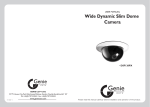
1
USER’S MANUAL UHF BAND Wind Instrument Wireless Microphone System WIRELESS MICROPHONE SYSTEM Table of Contents 1. Introduction.......................................................................................................... Page 1 1.1 FCC Statement 1.2 Safety 1.3 Environment 1.4 Wireless Note 2. Product Description............................................................................................ 2 2.1 Receivers 2.2 Wi5 Transmitter 3. Setting Up............................................................................................................ 5 3.1 Connecting the receiver to power 3.2 Connecting the receiver to an audio mixer or an amplifier 3.3 Setting up channel on receiver 3.4 Inserting batteries into the Wi5 transmitter 3.5 Setting up the Wi5 transmitter 4. Basic Connections............................................................................................. 9 5. Troubleshooting.................................................................................................. 10 6. System Features & Specification......................................................................... 11 7. Applied Microphone Warranty.............................................................................. 12 8. The “Wi5 Clamp”.................................................................................................... 14 WIRELESS WIRELESS NOTE 1. Introduction Thank you for purchasing our product. This PLL synthesized wireless microphone system operates in UHF band frequency with 16 selectable channels. Please read this instruction manual carefully before operating the system. This manual covers the function and operation of the wireless microphone system. 1.1 FCC Statement This device complies with part 15 of the FCC rules. Operation is subject to the following two conditions: (1)This device may not cause harmful interference and (2) This device must accept any interference received, including interference that may cause undesired operation Notice : The changes or modifications not expressly approved by the party responsible for compliance could void the user’s authority to operate the equipment. IMPORTANT NOTE: To comply with the FCC RF exposure compliance requirements, no change to the antenna or the device is permitted. Any change to the antenna or the device could result in the device exceeding the RF exposure requirements and void user’s authority to operate the device. 1.2 Safety ¾ Do not spill liquid on the appliance and do not drop it on a hard concrete floor. ¾ Do not place the appliance near heat sources such as radiators, amplifier, or etc. ¾ Do not expose it to direct sunlight, extremely dust, excessive moisture, or vibration. ¾ Take out the battery from transmitter, if the appliance has been not used for a longer period. This will avoid the damage resulting from a defective leaking battery. 1.3 Environment ¾ Do not throw used batteries into a fire or garbage bin with domestic rubbish. Be sure to dispose of used batteries in accordance with local waste disposal rules. ¾ When disposing the equipment, remove the batteries, separate the case, circuit boards, and cables, and dispose of all components in accordance with local waste disposal rules. 1.4 Wireless Note ¾ Before setting up, make sure that the transmitter and receiver are tuned to the same frequency. ¾ Do not use two transmitters in the same frequency. ¾ Use good quality batteries to avoid the damage resulting from a defective leaking battery. ¾ Turn the MIC/LINE switch on the rear of receiver to adjust receiver output level to match input level requirements of an audio mixer or amplifier. ¾ While checking sound, move the transmitter around the area where you use the system to look for dead spots. If you find any dead spot, change the receiver position. If it does not work, avoid such places. ¾ To avoid interference, do not put the receiver too near metal object and avoid obstructions between transmitter and receiver. ¾ Avoid the interference from TV, radio, other wireless appliances and etc. 1 PRODUCT DESCRIPTION WIRELESS 2. Product Description 2.1 Receivers The receivers are used with our 16-channel selectable channels transmitters. (The number of frequency channels depends on local regulations.) The receiver operates in UHF band frequency with PLL synthesized control. Powered by 12V DC. Single Channel, 1/2 Rack Switching Diversity, Fixed Antenna SET/SCAN POWER RF AF VOLUME DC OUT 1 6 7 2 3 4 5 8 15 AUDIO OUTPUT UNBALANCED SQUELCH DC ONLY 12V 500mA BALANCED 9 9 10 11 12 2 13 14 WIRELESS PRODUCT DESCRIPTION 1. Power: Press for 4 seconds to power the receiver on or off. 2. Channel Display: LED channel displays the channel number. 3. Button Ϧ: When the LED display starts flashing, press this button to change the channel forward. 4. Button ϯ: When the LED display starts flashing, press this button to change the channel in backward 5. Set / Scan Button: ¾ Set Channel: Press 1 second to let LED channel display flashing, then press the channel button Ϧ or ϯ to change the channel. Wait LED channel display flashing five times to lock the channel or press SET button for 1 second to lock the channel. 6. RF Level Indicators: 5-segment meter glows to indicate RF signal strength. more segment glow, the stronger the received signal. The If none of these segments glow, no signal is being received. 7. AF Level Indicators: 5-segment meter glows to indicate audio signal strength. more segment glow, the stronger the received signal. The If none of these segments glow, no signal is being input. 8. Level Control: Use this rotary control to adjust the receiver output level to match the input sensitivity of an audio mixer or an amplifier. 9. Antenna: Fixed-length UHF antenna permanently mounted. 10.Balanced Output: 3-pin XLR connector provides balanced low-impedance output 11.Unbalanced Output: Unbalanced 6.3mm mono jack audio output for connecting to, e.g., a guitar amplifier. 12.LINE-0dBV / MIC-20dBV Switch: Select output of XLR balanced connector or 6.ij unbalanced phone jack. It can be set for mic (-20dBV) or line (-0dBV). 13.Squelch Adj. : The squelch adjusts the output level to prevent from the external noise. Setting the squelch too high will reduce the range of the system. Set the squelch to minimum before turning the receiver on. 14.DC IN: DC input connector for the supplied AC adapter. 15.DC OUT: Connect the supplied cable to the receiver and the transmitter, and it takes around 10 hours to charge the re-chargeable batteries inside the transmitter. * Does not apply to Wi5 model transmitters. 3 WIRELESS PRODUCT DESCRIPTION 2.2 Wi5 Transmitter The Wi5 Transmitter operates in UHF band frequency with PLL synthesized control. UHF 16 preprogrammed selectable frequencies to avoid interference. Use 1 x DC1.5V AAA size dry or rechargeable batteries for low operating cost. 4 5 3 MUTE ON OFF 2 5 9 1 13 CHANNEL 1 6 7 8 1. On/Mute/off Switch: Turns transmitter power on, mute and off. 2. Low Battery LED: LED indicates battery life status. Switching the power to "ON". (1) The LED flashes once indicating that the transmitter has sufficient power. (2)The staying-on LED indicates that the battery has insufficient power and should be replaced soon. (3) If the status LED fails to flash, the battery is either dead or not positioned correctly. You should correct the position or replace a new battery. 3. Battery Cover: Push to open battery compartment cover. 4. Battery Compartment: Insert one AAA dry or rechargeable batteries into the compartment and make sure that the polarity of batteries is correct. 5. Antenna: Permanently connected, helical antenna. 6. Channel Selector: Use this selector to change transmitter channel setting. 7. Mini-XLR Plug: Connected to the microphone. 8. Velcro: Stick the Velcro on the bottom of transmitter and the surface of instrument. Make sure the position of the transmitter would be safe and fixed during the musician playing the instrument. 4 WIRELESS SET UP 3. Set Up 3.1 Connecting the Receiver AUDIO OUTPUT UNBALANCED SQUELCH DC ONLY 12V 500mA BALANCED 3OXJWKH'&9P$SRZHUVXSSO\LQWR WKHSRZHUFRQQHFWRURQWKHEDFNRIWKH UHFHLYHU AUDIO OUTPUT UNBALANCED DC ONLY 12V 500mA AC/DC ADAPTER SQUELCH BALANCED &RQQHFWWKHUHFHLYHURXWSXWWRWKHDXGLR PL[HURUDPSOLILHULQSXWXVLQJDVWDQGDUG DXGLRFDEOHZLWKSLQ;/5FRQQHFWRUVRU MSKRQHSOXJV1HYHUXVHWKHEDODQFHG DQGXQEDODQFHGDXGLRRXWSXWVDWWKHVDPH WLPH7KLVPD\FDXVHVLJQDOORVVRU LQFUHDVHGQRLVH AUDIO OUTPUT UNBALANCED SQUELCH DC ONLY 12V 500mA AC/DC ADAPTER BALANCED %DODQFHGRUXQEDODQFHGDXGLRFDEOH $8',20,;(R LOUDSPEAKER $03/,),(R 0DWFKLQJWKH0LF/LQHVHOHFWRUSRVLWLRQRI UHFHLYHUZLWKWKHDXGLR0L[HUEHIRUH FRQQHFWLQJZLWK0L[HU )RU0LFG%9 )RU/LQHG%9 AUDIO OUTPUT UNBALANCED SQUELCH DC ONLY 12V 500mA BALANCED 5 SET UP MANUAL MODE 3.2 Set up interference-free channel on receiver Notice: Do not put two or more transmitters operate nearby when set up the frequency channel. Please keep transmitter at least 1 M away from receiver. 3.2.1 Manual Mode Set up interference -free channel by manual operation. ¾ Press the button to turn the power on. POWER R SET/SCAN RF RF RF AF ¾ Press button “SET/SCAN” for 1 second to let channel flashing on the LED display. SET/SCAN ¾ Press button CH for 2 seconds to change the channel forward or backward. SET/SCAN ¾ Stop pressing button and let LED display flashing five times to lock the setting. AF AF 6 AUTO-SCAN MODE SET UP 3.2.2 Auto-Scan Mode Set up interference-free channel by auto-scan programmed search. Press the button to turn the power on. POWER R Press button “Set/Scan” for 3 seconds to search the next interference-free channel automatically. SET/SCAN RF AF The auto-scan system would stop at the next interference-free channel. Stop pressing button and let LED display flashing five times to lock the setting. SET/SCAN RF AF NOTE: If user need to set up a multi-receiver system, please keep your previous receiver-microphone pair power on. Then go on to next scanning procedure. 7 SET UP MANUAL MODE 3.4 Inserting batteries into the Wind Instrument transmitter ¾ Push to open the battery cover and insert a battery into the battery compartment conforming to the polarity (+)(-) marks. The transmitter can not work with incorrectly inserted battery. ¾ Pushing the ON/MUTE/OFF switch to “ON” to switch the power-on position, the LED will flash momentarily. MUTE ON OFF (1)The LED flashes once when the battery has sufficient power. (2)The staying-on LED indicates that the battery has insufficient power and should be replaced soon. (3)If the status LED fails to flash, the battery is either dead or not positioned correctly. You should correct the position or replace a new battery. ¾ Push back the battery cover to click it shut. 3.5 Setting up the wind instrument transmitter CHANNEL 1 SET/SCAN POWER RF AF 5 13 VOLUME DC OUT ¾ Check if the receiver is tuned to the same frequency as the transmitter. 9 5 1 9 13 CHANNEL F ¾ Set the MIC/LINE switch on the back of receiver to “LINE” or “MIC” according to user choice. AUDIO OUTPUT UNBALANCED NCED SQUELCH DC ONLY 12V 500mA BALANCED ¾ Switch the transmitter power on. MUTE ON OFF ¾ Play the instrument for testing and adjust the levels on your audio mixer or amplifier. 8 WIRELESS 4. BASIC CONNECTIONS To combine two receivers in a 19” standard rack by using 2 short L type plastics racks (L2) and 2 metal connecting plates (C1). (Each system includes a L2 and a C1.) L2 C1 To mount a receiver in a 19” standard rack by using 2 L type long metal racks (L1). (L1 is an optional product, please contact AMT directly for more information.) L1 9 WIRELESS TROUBLESHOOTING 5. Troubleshooting Problem Solution No sound ¾ Check the power supply of the transmitter and receiver. ¾ Check that the transmitter and receiver are tuned to the same frequency. ¾ Check whether the hi-fi appliance is switched on and the receiver output is connected to audio mixer or amplifier input. ¾ Check whether transmitter is too far away from receiver or SQUELCH control set too high. ¾ Check whether receiver is located too near metal object or there are obstructions between transmitter and receiver. Sound interference ¾ Check the antenna location. ¾ When using 2 or above transmitter sets simultaneously, make sure that the chosen frequencies are not interfered. ¾ Check whether the interference comes from other wireless microphones, TV, radio and etc. Distortion ¾ Check the receiver volume level is set too high or too low. ¾ Check whether the interference comes from other wireless microphones, TV, radio and etc. 10 WIRELESS Features & Specification 6. Wi5 System Features ¾ Operating in UHF band frequency with synthesizer controlled. ¾ The wireless microphone system with 16 selectable frequencies via Phase Locked Loop (PLL) circuitry makes it easy to choose non-interfered channels. ¾ Diversity with two antennas to ensure the reception quality. ¾ Super high sensitivity, extremely low noise transmission and reception. ¾ SMT assembled PCB module ensures the quality and stability. 6.1 System Specification Receiver ¾ Carrier Frequency Range : UHF band ¾ ¾ ¾ ¾ ¾ ¾ ¾ ¾ ¾ ¾ ¾ : ±0.005% : At 8 dBӴV Frequency Stability Receiving Sensitivity Image and Spurious Rejection Selectivity Modulation Mode IF Frequency Tone Signal S/N ratio AF Response T.H.D. Power Supply over 80dB S/N ratio : 80 dB minimum : Ї50dB : FM st nd : 1 : 56MHz; 2 : 10.7MHz : 32.768KHz : Ї94dB, at 48KHz deviation and 60dB%V antenna input : 80Hz to 12KHz (±3dB) : Less than1.0% (at 1KHz) : DC 12V ~ 18V ¾ Audio Output : Balanced and unbalanced outputs (Mic.=-20dBV / Line = 0dBV) ¾ Battery Charging ¾ Current consumption : Without Charging Function : 150mA (Max.) A Wi5 Transmitter ¾ Carrier Frequency Range : UHF band ¾ Modulation : FM ¾ RF Power Output : 10mW (max.) ¾ Oscillation Mode : PLL synthesized, 16Channel selectable ¾ Frequency Stability : ±0.005% ¾ Maximum Deviation : ±48KHz with limiting compressor ¾ Spurious Emission : Ї60dB below carrier frequency ¾ T.H.D. : І1% (at 1KHz) ¾ Tone Signal : 32.768KHz ¾ Battery : 1 x 1.5V AAA size batteries or 1 x 1.2V AAA size rechargeable batteries : 130mA at 1.5V ¾ Current consumption 11 WIRELESS APPLIED MICROPHONE WARRANTY AMT Limited Warranty. Duration of this warrantee will remain in effect for one year from the date of the original purchase. This warranty may be enforced by the original dated sales receipt or other proof of warranty coverage is presented when warranty service is required. What is covered? Except as specified below, this warranty covers all defects in materials and workmanship in this product. The following are not covered by the warranty: ¾ 1. Damage resulting from accident, misuse, abuse or neglect. ¾ 2. Failure to follow instructions included with microphone. ¾ 3. Repair of attempted repair by anyone not authorized by A.M.T. ¾ 4. Failure to remove battery when storing. ¾ 5. Cause other than product defects including: lack of skill, competence, or experience of use. ¾ 6. Damages occurring during any shipment of this product (claims must be presented to carrier). ¾ 7. Damage to any unit which has been altered, or which the serial number has been defaced, modified, or removed. AMT will pay all labor and material expense for covered items. Shipping charges are discussed later in this warranty. If your unit needs service, please write or telephone us and we will advise you where the unit should be taken or sent. If you write us, include your name, complete address, daytime telephone number, and a description of the problem. DO NOT RETURN YOUR UNIT TO AMT WITHOUT A REPAIR AUTHORIZATION NUMBER. If it is necessary to ship the product for service: ¾ 1. You must pay initial shipping charges, but if necessary repairs are covered by the warrantee, AMT will cover the return shipping charges via carrier of AMT's choice to any destination within the United States. ¾ 2. Whenever warranty service is required a copy of the original dated sales receipt must be presented. ¾ 3. For products purchased outside of the USA, please contact 973-222-1865 for information pertaining to your country. Exclusion of certain damages: AMT's liability for any defective product is limited to repair of replacement of the product of our option. AMT shall not be liable for damages based upon inconvenience, loss of use of the product, loss of time, interrupted operation, commercial loss; or any other damages whether incidental, consequential, or otherwise. Some states do not allow limitations an implied warrantee lasts, and/or do not allow the exclusion or limitations of incidental or consequential damages, so the above limitations may not apply to you. This warrantee is not enforceable outside of North America. This warrantee gives you specific legal rights, and you may also have other rights which vary from state to state. 12 APPLIED MICROPHONE WARRANTY WIRELESS For International Customers (Outside of the United States): If the product is purchased inside of the United States and taken to another country, it is the responsibility of the product owner to cover all shipping, customs, and duty if a warranty, upgrade, and repair issue is necessary. All provisions of the warranty above apply except for Shipping and all costs related to shipping. Ie.. Customs charges and V.A.T. are not covered by AMT. All outside charges associated with re-entry of the product into the USA is the sole responsibility of the product owner. At no time shall a distributor or a dealer take it upon themselves to replace a defective system with a new system. This can only be done with the permission of AMT’s tech support (973-222-1865) directly or through a distributor of the country purchased with AMT tech support approval. Repairs: ¾ 1. The customer, dealer, or distributor should contact AMT tech support via phone (973-729-9333 E.S.T. 12pm - 12am) or email with a short description of the problem. Skype phone calls are also welcome: SKYPE: AMTTECHSUPPORT ¾ 2. If out of warranty, we then advise the customer to call by phone to our tech support 1-973-222-1865 for a return authorization and to discuss possible solutions before sending. ¾ 3. Date and origin of purchase required for warranty repair. If the product is covered under warranty, the product must ship back to AMT, when completed; AMT will ship it back with the distributor’s next order. Under warranty regulations, if a product has been damaged from miss-use such as: •Damage resulting from accident, misuse, abuse or neglect. •Failure to follow instructions included with microphone. •Repair or attempted repair by anyone not authorized by AMT. •Failure to remove battery when storing. •Cause other than product defects including: lack of skill, competence, or experience of use. •Damages occurring during any shipment of this product (claims must be presented to carrier). •Damage to any unit which has been altered, or which the serial number has been defaced, modified, or removed. ¾ 4. Most common problems found to be are over stressed goosenecks, broken cables, and plugs that have been crushed or bent. These problems are NOT covered under warranty BUT in certain cases, if the shipping is taken care of both ways, we will repair it for free. Due to this unique product, which is specialized in the audio field, most components that make up this product are proprietary. In most cases, the entire product must be taken apart to its manufacturing stage in order to rebuild or replace damaged components. This makes it almost impossible to use outside of the USA repair stations. 13 The “Wi5 Clamp” WIRELESS Clamp Instructions - Wi5 Wireless Microphone System The Wi5 comes complete with a clamp for flanged bell instruments such as saxophone, trumpet, and trombone bells. The Wi5 can mount to additional instruments such as percussion, accordion, and clarinet with the purchase of optional clamps. Wi5 Clamp Optional Clamping systems: Clarinet Clamp Bass Clarinet Clamp ERT Percussion Clamp ACCX Accordion Clamp 14