1
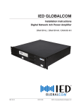
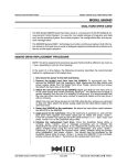
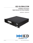
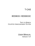
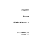
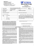
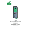
IED GLOBALCOM
Installation Instructions
IED Announcement Control System
IED1100 / IED1200
REV: 08-12
DOC1201B
©2012, Innovative Electronic Designs, LLC
IED GLOBALCOM IED1100 / IED1200
INSTALLATION INSTRUCTIONS
Copyright © 2012 Innovative Electronic Designs, LLC. All Rights Reserved
If this document is distributed with software that includes an end user agreement, this document, as well as the software described
in it, is furnished under license and may be used or copied only in accordance with the terms of such license. Except as permitted by any such license, no part of this document may be reproduced or transmitted in any form or by any means, electronic or
mechanical, including photocopying, recording, storage in an information retrieval system, or otherwise, without the prior written
permission of Innovative Electronic Designs, LLC. Please note that the content in this guide is protected under copyright law even if
it is not distributed with software that includes an end user license agreement.
The content of this document is furnished for informational use only and is subject to change without notice. It should not be construed as a commitment by Innovative Electronic Designs, LLC. Innovative Electronic Designs, LLC assumes no responsibility or
liability for any errors or inaccuracies that may appear in the informational content contained in this document.
Any reference to company names in examples are for demonstration purposes only and are not intended to refer to any actual
organization or an endorsement of any kind.
Innovative Electronic Designs, IED, 500ACS, 500ACS Announcement Control System, CAS, Courtesy Announcement System,
T-CAS, FAS, Flight Announcement System, IED On Call, IED On Call & Design, and LANcom are all registered trademarks or trademarks of Innovative Electronic Designs, LLC in the United States and/or other countries.
CobraNet is a registered trade mark of Cirrus Logic in the United States and/or other countries.
Microsoft, Windows, Windows Vista, Windows 7, Windows Server, SQL Server, and Internet Explorer are all registered trademarks
or trademarks of Microsoft Corporation in the United States and/or other countries.
Innovative Electronic Designs, LLC
9701 Taylorsville Road
Louisville, KY 40299
United States of America
www.iedaudio.com
Document Number: 1201B
PAGE ii
DOC1201B
REV: 08-12
INSTALLATION INSTRUCTIONS
IED GLOBALCOM IED1100 / IED1200
TABLE OF CONTENTS
IMPORTANT SAFETY INSTRUCTIONS........................................................................................ 2
SAFETY SYMBOLS............................................................................................................... 2
SAFETY CONSIDERATIONS......................................................................................................... 3
SAFETY PRECAUTIONS...................................................................................................... 3
GENERAL PRECAUTIONS................................................................................................... 3
PRELIMINARY PRECAUTIONS............................................................................................ 3
PRECAUTIONS WHEN MEASURING HIGH VOLTAGE POTENTIALS................................. 4
PRECAUTIONS WHEN WORKING ON ENERGIZED EQUIPMENT..................................... 4
AC POWER CIRCUITS.......................................................................................................... 4
RESUSCITATION.................................................................................................................. 5
DESCRIPTION............................................................................................................................... 5
CONNECTIONS............................................................................................................................. 6
IED1100/1200 INSTALLATION...................................................................................................... 8
UNPACKING AND PREPARING THE UNIT.......................................................................... 8
INSTALL UNIT INTO A RACK............................................................................................... 8
OPTIONAL – CONNECT KEYBOARD, MOUSE AND MONITOR......................................... 9
CONNECT NETWORK CABLES......................................................................................... 10
CONNECT LOGIC AND RELAY I/O (IED1200 ONLY)......................................................... 10
CONNECT POWER PLUG.................................................................................................. 11
COMPLETE UNIT CONFIGURATION................................................................................. 12
SPECIFICATIONS........................................................................................................................ 13
FCC NOTICE................................................................................................................................ 13
REV: 08-12
DOC1201B
PAGE 1
IED GLOBALCOM IED1100 / IED1200
INSTALLATION INSTRUCTIONS
IMPORTANT SAFETY INSTRUCTIONS
1.
Read these instructions.
2.
Keep these instructions.
3.
Heed all warnings.
4.
Follow all instructions.
5.
Do not use this apparatus near water.
6.
Clean only with dry cloth.
7.
Do not block any ventilation openings. Install in accordance with
the manufacturer’s instructions.
8.
9.
12.
Use only with the cart, stand, tripod, bracket,
or table specified by the manufacturer, or
sold with the apparatus. When a cart is used,
use caution when moving the cart/apparatus
combination to avoid injury from tip-over.
13. Unplug this apparatus during lightning storms or
when unused for long periods of time.
14. Refer all servicing to qualified service personnel. Servicing is required when the apparatus has been damaged in any way, such as power-supply cord or plug
is damaged, liquid has been spilled or objects have
Do not install near any heat sources such as radiators, heat
fallen into the apparatus, the apparatus has been exregisters, stoves, or other apparatus (including amplifiers) that
posed to rain or moisture, does not operate normally,
produce heat.
or has been dropped.
Do not defeat the safety purpose of the polarized or groundingtype plug. A polarized plug has two blades with one wider than
CAUTION
the other. A grounding type plug has two blades and a third
RISK OF ELECTRIC SHOCK
grounding prong. The wide blade or the third prong is provided
DO NOT OPEN
for your safety. If the provided plug does not fit into your outlet,
RISQUE DE CHOC ELECTRIQUE
NE PAS OUVRIR
consult an electrician for replacement of the obsolete outlet.
10. Protect the power cord from being walked on or pinched particularly at plugs, convenience receptacles, and the point where
they exit from the apparatus.
11. Only use attachments/accessories specified by the manufacturer.
CAUTION: TO REDUCE THE RISK OF ELECTRIC SHOCK
DO NOT REMOVE COVER (OR BACK)
NO USER SERVICEABLE PARTS INSIDE
REFER SERVICING TO QUALIFIED PERSONNEL
WARNING: To reduce the risk of fire or electric shock, do not expose this apparatus to rain, moisture, dripping,
splashing, or place objects filled with liquids on the equipment.
WARNING: If apparatus is equipped with Class I grounding plugs for safety purposes, it must be connected to
MAINS that employ a protective earth ground connection.
WARNING: The MAINS plug on this device may be used as the DISCONNECT DEVICE for MAINS power and must
remain readily operable.
WARNING: Installation and maintenance of IED equipment is to be made by trained/qualified personnel and must
conform to all applicable local codes.
WARNING: If unit contains a lithium battery, there is a danger of explosion. Replace only with the same or equivalent
type.
SAFETY SYMBOLS
Labeling on products and the Installation Instructions & User Manual may use safety related graphical symbols as shown below to note safety requirements.
Lightning Bolt: The lightning flash with arrowhead symbol, within an equilateral triangle, WARNING symbol, is intended to alert the user to the presence of uninsulated dangerous voltage within
the product’s enclosure that may be sufficient in magnitude to constitute a risk of electric shock to
persons or domestic animals.
Exclamation Point: The exclamation point within an equilateral triangle, CAUTION symbol, is
intended to alert the user to the presence of important operating and maintenance (servicing)
instructions, or a hazard that can damage equipment.
Do not proceed beyond a WARNING or CAUTION notice until you have understood the hazardous condition and have taken appropriate steps.
Ne continuez pas avant d’avoir pris connaissance du danger et prendre les mesures appropriées.
PAGE 2
DOC1201B
REV: 08-12
INSTALLATION INSTRUCTIONS
IED GLOBALCOM IED1100 / IED1200
SAFETY CONSIDERATIONS
SAFETY PRECAUTIONS
Personnel properly qualified in the application and use of life safety equipment (“qualified personnel”) shall
read this manual carefully before performing any actions to specify, apply, install, maintain and perform operational tests of IED systems, and associated products in accordance with the instructions in this manual.
This manual shall be made available to all qualified personnel who operate, test, maintain, or service IED
systems, and associated products. It is strongly recommend that such personnel read and understand the
entire manual.
WARNING: IF SAFETY PRECAUTIONS, INSTALLATION AND TESTING ARE NOT PERFORMED PROPERLY, CONDITIONS COULD EXIST IN WHICH THE IED SYSTEM MAY NOT OPERATE, OR MAY OPERATE IMPROPERLY. THIS COULD RESULT IN PROPERTY DAMAGE AND SERIOUS INJURY OR DEATH
TO YOU AND/OR OTHERS.
It is very important that only responsible, trained personnel are allowed to operate and maintain these systems, and that they use only appropriate equipment and tools. If a person is not trained, they shall contact
the IED factory for direction on how to operate and maintain an IED system.
Unauthorized personnel and equipment must be restricted from the areas of operation.
All operations should be performed carefully, methodically, and without hurrying. Greater effectiveness will
be developed by increased familiarity of personnel with their assignments. During any maintenance operation, if a malfunction occurs or an incorrect indication appears, stop the operation and determine whether
or not it is safe to proceed. Before performing any step in a procedure, be sure that the preceding step has
been properly executed and correct results obtained. Cleanliness and good housekeeping in all installation
areas are major factors in effective accident prevention. Tools and equipment should be maintained in good
working order and should always be returned to their proper storage place after usage. Cleaning agents
and other cleaning aids should be removed from the equipment areas immediately upon completing the
task at hand.
GENERAL PRECAUTIONS
Changes, modifications, or additions in connection with the IED system equipment shall not be made without explicit authorization of IED.
Safety devices found on mechanical, and electrical and electronic equipment are put there for the protection of personnel and equipment. These devices must be maintained in good working order and operative
at all times. Safety devices shall never be removed or bypassed unless specifically authorized by the IED
factory. Where safety devices have been rendered inoperable by proper and specific authorization, adequate notices shall be posted to warn personnel of the potential hazard.
Avoid the use of flammable or toxic cleaning fluids, and the use of carbon tetrachloride is prohibited.
Maintenance of the equipment shall be at least what is specified in the IED manuals and literature, and
performed only by qualified personnel.
Whenever operation and maintenance is ongoing, personnel in the equipment areas shall have an effective
communication among these areas in order to protect people if any accident occurs.
PRELIMINARY PRECAUTIONS
Precautions which are applicable to general electrical or electronic maintenance are as follows:
a. Check yourself. Wear no article that might catch on equipment or that might act as a conductor.
b. Check the working area. The equipment area shall be clean and dry. If possible, stand on a special
insulator such as a rubber mat. There should be ample working space and good lighting.
c. Check the tools. Always use proper tools and check them for their safe condition. Use screwdrivers
with plastic handles. Check test equipment periodically and examine test leads carefully as the slightest break in insulation is dangerous.
REV: 08-12
DOC1201B
PAGE 3
IED GLOBALCOM IED1100 / IED1200
INSTALLATION INSTRUCTIONS
d. Check the procedures. Study the entire procedure before taking the first step. Consult the circuit diagram frequently to obtain an understanding of what is accomplished at each step. Know what is in the
equipment and how it differs from others on which you have worked.
e. Be aware that high voltages may be present across terminals that are normally low voltage, due to
equipment breakdown. Be careful when measuring low voltages in equipment containing high voltage
circuits.
f. Do not make resistance measurements with power on.
g. Do not work within the equipment without the presence of a person who is capable of rendering aid,
and who is familiar with the procedure for emergency shutdown of the equipment.
PRECAUTIONS WHEN MEASURING HIGH VOLTAGE POTENTIALS
Observe the following precautions when measurements must be performed on circuits with potentials over
48 volts.
a. Do not measure potentials over 48 volts without the presence or assistance of a person who is capable
of rendering aid, and who is familiar with the procedure for emergency shutdown of the equipment.
b. Be sure you are not grounded when you are adjusting equipment or using measuring equipment.
Stand on a rubber mat or other insulator if possible. Be sure the equipment area is clean and dry. In
general, use only one hand when servicing live equipment.
c. If a test meter must be held or adjusted while voltage is applied, ground the case of the meter before
starting a measurement. Do not touch the live equipment or personnel working on live equipment while
holding the meter. The “common” terminal on some A/C electronic voltmeters is at ground potential;
never connect the “common” terminal to any point above ground potential.
d. High-voltage, high-capacitance capacitors should be discharged before servicing is started.
WARNING! Discharging must be done carefully and judiciously. First ascertain whether there is a
built-in bleeder network. If so, wait a minute or two for the capacitor to discharge through the
network. Otherwise, use an external discharge network. This is most important in the case of high
voltage or high capacitance capacitors. If one terminal is connected to ground, connect the
discharge network between the other terminal and ground. If neither terminal of the capacitor is
grounded, connect the network across the capacitor terminals. Connecting a short circuit across
the terminals is not recommended. Doing so can produce extremely high currents and a flash
which can injure the eyes, vaporize metals, and cause burns.
PRECAUTIONS WHEN WORKING ON ENERGIZED EQUIPMENT
When it is necessary to work on energized equipment, think ahead and anticipate every hazard. Never work
alone on energized equipment.
Interlock switches are installed on some of the doors and panels to break the power circuits when the
enclosure is entered. When it is necessary to work within such an enclosure on energized equipment, the
interlock may be bypassed. Extreme caution should then be exercised, as dangerous voltages are present
within the unit.
AC POWER CIRCUITS
Equipment obtaining power from a secondary distribution system should be grounded at all times by
means of a third grounding wire on the power lines. Equipment permanently wired to a secondary distribution system should also be grounded separately by connection to a grounding bus or ground rod with a
sufficiently large conductor to handle the current expected if the secondary source is accidentally shorted
to the equipment.
The ground wire should be protected from mechanical damage and periodically inspected for good physical condition.
PAGE 4
DOC1201B
REV: 08-12
INSTALLATION INSTRUCTIONS
IED GLOBALCOM IED1100 / IED1200
Personnel should never depend on a switch to remove power from equipment. If the equipment is connected to the secondary distribution system by means of a power cable, detach the cable from the receptacle
before attempting any repairs of removal of chassis.
If the equipment is permanently wired to the secondary distribution system, remove the main fuses or open
the power switch. Attach a suitable warning tag to the switch which will warn personnel not to operate the
equipment; only the person who originally attaches the warning tag should be authorized to remove it.
RESUSCITATION
Personnel working with or near high voltage should be familiar with modern methods of resuscitation. Such
information and training is available from the Red Cross or local emergency response personnel such as
the police and fire departments.
DESCRIPTION
The IED1100 is an integrated control system containing a micro-controller with integrated storage media,
data network interface, and an audio network interface. The IED1200 includes the same internal hardware
with the addition of logic input ports and relay outputs. The system functions performed by the unit are
determined by the software configuration provided with the unit. Using the 1000vACS software platform, the
following configurations are available for purchase.
REV: 08-12
IED1100ACS-32
This configuration includes an IED1100 unit bundled with the Announcement Control System software configuration. This unit provides an announcement controller with built-in message functionality.
This configuration includes a license to use up to 32 zone outputs
with the option to upgrade to 64, 128, or unlimited zone outputs. The
system has the ability to support up to two (2) channels of VoIP for
telephone paging.
IED1200ACS-32
This configuration includes the IED1200 unit with the same software
functions of the IED1100ACS-32 with addition hardware functionality.
It includes the ability to read contact closure inputs to trigger various
functions as well as provide relay outputs to control external devices.
IED1100MSG
This configuration includes the IED1100 unit bundled with the Message Server software configuration. This unit provides an expansion
of the messaging capability of a system using an IED1100ACS or
IED1200ACS. It will also function as a messaging device in systems
that use the 1000vACS software hosted on a server-based platform.
IED1200MSG
This configuration includes the IED1200 unit with the same software
functions as the IED1100MSG with the addition of logic inputs and
relay outputs.
IED1100TEL
This configuration includes the IED1100 unit bundled with SIP Telephone Interface software. This unit provides an expansion of the VoIP
telephone interface capacity of a system using the IED1100ACS or
IED1200ACS. It has a maximum capacity of eight (8) simultaneous
telephone interface lines.
DOC1201B
PAGE 5
IED GLOBALCOM IED1100 / IED1200
INSTALLATION INSTRUCTIONS
CONNECTIONS
1
3
2
Figure 1 - IED1100 / IED1200 Front View
5
6
7
4
8
9
10
+
CobraNet
12 vdc
Figure 2 - IED1100 Rear View
5
6
7
8
10
4
9
11
Logic Inputs
+1
Relay
+
CobraNet
12 vdc
_
+
2
_
+
3
NC C NO NC C NO NC C NO NC C NO
1
3
2
4
_
+
4
_
12
Logic Inputs
+5
_
+
6
Relay
_
+
7
_
+8
_
NC C NO NC C NO NC C NO NC C NO
5
7
6
8
Figure 3 - IED1200 Rear View
1. Power LED
This LED will illuminate when the unit is powered on.
2. HD LED
This LED will flash to indicate activity when the unit is accessing the internal storage drive.
3. USB Port
This USB 2.0 compliant port is located on the front panel to provide a convenient place to connect
an external flash storage device for file transfers.
4. Power
This connector is used to connect the unit to either the included single IED1112PSD power supply
module or the IED1112PS rack-mount power supply. This 12VDC jack accepts a 2-pin Phoenix
plug with 3.81mm spacing.
5. VGA Monitor Out
This analog video output is used to attach a monitor to the unit. It supports resolutions up to a
maximum of 2048 x 1536 (QXGA) at 75Hz refresh rate.
PAGE 6
DOC1201B
REV: 08-12
INSTALLATION INSTRUCTIONS
IED GLOBALCOM IED1100 / IED1200
6. DVI-D Monitor Out
This digital video output (DVI 1.0) is used to attach an external monitor that supports digital video.
It supports a maximum resolution of 1600 x 1200 (UXGA)
7. USB Ports (3)
Use these three USB 2.0 compliant ports to connect a keyboard and mouse to the unit. The remaining port can be used to attach an external storage device for system backup or file transfers.
8. Control Network
This 10/100/1000 Mbits/sec Ethernet LAN port is used to connect the unit to the network using a
standard RJ45 connector. This port transmits and receives control data only. The digital audio from
the device is transmitted using the audio network port. Two LEDs are provided to indicate status as
shown in the table below.
LED
Link (left)
Speed (right)
State
Condition
Off
LAN link not established
Green (solid)
LAN link is established
Green (blinking)
LAN activity occurring
Off
10 Mb/s data rate
Green
100 Mb/s data rate
Yellow
1000 Mb/s data rate
9. Audio Network
This 100 Mbits/sec Ethernet LAN port is used to connect the digital audio channels of the device
to the network using a standard RJ45 connector. Two LEDs are provided to indicate the status as
shown in the table below.
Condition
Left LED
Right LED
Conductor
Flashing Orange
Flashing Green
Performer
Solid Orange
Flashing Green
Fault
Flashing Orange
Flashing Orange
10. 1/8” Mini Phone Connector
This connector is not used.
IED1200 Only
11. Logic Inputs
Eight (8) logic inputs provide a simple method to interface the IED1200 to other systems such as
fire alarm panels, building management systems, security systems, etc.. The function of each input
is programmed in the system software.
12. Relay Outputs
Eight (8) dry contact relay outputs are provided to send signals from the IED1200 to other systems
such as fire alarm panels, building management systems, security systems, etc.. Each relay is programmed in the system software. Relays can be programmed to act as zones and trip each time
an announcement or message is active for that zone. Relays can also be used to provide a closure
when there is a fault condition present in the system.
REV: 08-12
DOC1201B
PAGE 7
IED GLOBALCOM IED1100 / IED1200
INSTALLATION INSTRUCTIONS
IED1100/1200 INSTALLATION
WARNING! Before performing the following procedure, review the safety instructions on the previous pages.
NOTE: This equipment is intended for installation in a restricted access location.
UNPACKING AND PREPARING THE UNIT
Unpack the unit from its shipping carton and identify any accompanying components that may have been
included. Attach the rack ears as shown in Figure 4 to allow the unit to be mounted in a standard 19” equipment rack. Adjust the ear positions so the front of the ear is even with the front of the unit and tighten the
screws securely.
Figure 4 - Attaching Rack Mount Ears to the Unit
Two types of external 12VDC power supplies are available. The IED1112PSD is an in-line power supply
module that provides power to the unit for situations that do not require power supply redundancy. The
IED1112PS is a rack-mount power supply unit with optional redundant power supply modules to provide
uninterrupted power to the unit should a supply fail.
If the unit will be used with the IED1112PS, locate the adaptor cable that will be used to connect the two
units. If the unit will use the IED1112PSD in-line power supply, then locate this unit and prepare it for installation as shown later in this manual.
INSTALL UNIT INTO A RACK
The IED1100/1200 requires one rack unit (1 RU) of available space and a recommended mounting depth of
18” to allow adequate clearance for cabling. Select a location in the 19” rack for the unit based on proximity
to the rack mounted 12V power supply system, keyboard and monitor or a KVM (keyboard/video/mouse)
switch unit. Mount the unit using suitable screws for the rack being used, two per rack mount ear. Please
refer to any safety and installation instructions that came with the rack prior to assembly.
PAGE 8
DOC1201B
REV: 08-12
INSTALLATION INSTRUCTIONS
IED GLOBALCOM IED1100 / IED1200
Figure 5 - Mounting Unit in a Rack
OPTIONAL – CONNECT KEYBOARD, MOUSE AND MONITOR
The unit may be connected to keyboard, mouse and monitor either directly or via a KVM switch shared with
other devices in the rack.
Figure 6 - Connecting Keyboard, Mouse and Monitor
Connect the keyboard and mouse to two of the available USB ports on the back of the unit. Connect the
monitor to either the VGA output (15-pin D shell connector) or the DVI-D output on the back as appropriate
for the type of monitor being used.
REV: 08-12
DOC1201B
PAGE 9
IED GLOBALCOM IED1100 / IED1200
INSTALLATION INSTRUCTIONS
CONNECT NETWORK CABLES
Figure 7 - Connecting Network Cables
The unit has two Ethernet ports located on the rear of the unit. Both ports must be connected for proper
operation. One is used for control and data while the other is dedicated strictly for digital audio. Connect
both ports to available Ethernet switch ports using a suitable Cat-5e or Cat-6 jumper cable. The switch ports
should be configured for auto-negotiation 10/100 or 10/100/1000.
CONNECT LOGIC AND RELAY I/O (IED1200 ONLY)
The IED1200 provides eight (8) logic sensor inputs and eight (8) dry contact outputs that can be used to
trigger announcements, mute the system, provide control to external systems, or indicate a fault status. As
required for the application, attach logic input lines and relay output lines to the terminal blocks provided,
as shown in Figure 8 and Figure 9.
Figure 8 - Connecting Logic and Relay Lines
Each logic input is isolated and terminations are made by connecting the signal to the + terminal while
using the – terminal for the return path to the signaling device. Pins 5 and 10 on each connector provide a
reference to chassis ground. Refer to Figure 9 for details on the logic and relay terminals.
PAGE 10
DOC1201B
REV: 08-12
INSTALLATION INSTRUCTIONS
Isolated logic
input and
return
IED GLOBALCOM IED1100 / IED1200
Chassis
ground
Normally
Closed relay
contact
Common
relay contact
Normally
Open relay
contact
Figure 9 - Logic and Relay Connector Detail
CONNECT POWER PLUG
Figure 10 - Connect 12V Power Plug
REV: 08-12
DOC1201B
PAGE 11
IED GLOBALCOM IED1100 / IED1200
INSTALLATION INSTRUCTIONS
Connect the cable from the IED1112PSD in-line 12V power supply or the IED1112PS rack mount 12V power
supply system to the power connection on the back of the unit. If main power is present, the unit will immediately boot up. The fan will run and the power LED on the front panel will illuminate.
COMPLETE UNIT CONFIGURATION
Once the unit is booted up, complete the system configuration using the supplied configuration software.
This is accomplished using either a keyboard, mouse and monitor connected directly to the unit or via remote connection through the network. Refer to the appropriate user guides for the specific model configuration to complete the unit setup.
PAGE 12
DOC1201B
REV: 08-12
INSTALLATION INSTRUCTIONS
IED GLOBALCOM IED1100 / IED1200
SPECIFICATIONS
ELECTRICAL, ANALOG
1. Supply Voltage..................................................................................................................................... 12V DC
2. Rated Input Current.......................................................................................................... 2 Amps Max (24W)
3. Relay Contact Rating.......................................................................................................... 1A @ 30VDC Max
MECHANICAL
1.
2.
3.
4.
Height........................................................................................................................................ (4.4 cm) 1.75”
Width (without rack mount ears)............................................................................................... (43.2 cm) 17”
Depth..................................................................................................................................... (31.1 cm) 12.25”
Weight................................................................................................................................(4.92 kg) 10.85 lb..
ENVIRONMENTAL
1. Operating Temperature Range..................................................................... (+32 °F - +95 °F) 0 °C - +35 °C
2. Storage Temperature Range......................................................................(–4 °F - +158 °F) –20 °C - +70 °C
CONNECTORS
1.
2.
3.
4.
5.
6.
7.
Power........................................................................... 2-pin Phoenix, 3.81mm spacing with locking screws
USB......................................................................................................................................... 3 Rear / 1 Front
Ethernet (2)................................................................ Digital Audio (100Mbps) Control (10/100/1000 Mbps)
Video (2)........................................................................................................................................... VGA / DVI
Audio Out.............................................................................................................................. 1/8” Stereo Jack
Opto Isolated Logic Inputs (typical of 2)....................................................10-pin Phoenix, 3.81mm spacing
Relay Outputs (typical of 2)........................................................................12-pin Phoenix, 3.81mm spacing
COMPLIANCE
1. SAFETY:
UL60950-1 (Ed.2) Listed
CAN/CSA C22.2 No. 60950-1-07 (Ed.2) Certified
IEC 60950-1: 2005; AM 1:2009
EN 60950-1:2—6/A11:2009/A1:2010
CB Certificate
2. FCC / EMC:
CFR, Title 47, Chapter I, Part 15 Subpart B
ICES-003, Issue 4, 2004
AS/NZS CISPR 22: 2005
CISPR 22 (Ed.5): 2005 +A1 (EN 55022: 2006 +A1)
CISPR 24 (Ed.1): 1997 +A1, A2 (EN 55024:1998 +A1, +A2)
IEC 61000-3-2 (Ed.3): 2005, +A1,A2 (EN 61000-3-2:2006)
IEC 61000-3-3 (Ed.2): 2008 (EN 61000-3-3:1995 +A1, +A2)
FCC NOTICE
This device complies with part 15 of the FCC Rules. Operation is subject to the following two conditions:
1. This device may not cause harmful interference.
2. This device must accept any interference received, including interference that may cause
undesired operation.
REV: 08-12
DOC1201B
PAGE 13
Innovative Electronic Designs, LLC
9701 Taylorsville Road
Louisville, KY 40299, USA
REV: 08-12
+1.502.267.7436 phone
+1.502.267.9070 fax
www.iedaudio.com
DOC1201B
©2012, Innovative Electronic Designs, LLC