1
Cat. No. W448-E1-05
SYSMAC
CXONE-AL_C-V4/
CXONE-AL_D-V4
CX-Motion-MCH
OPERATION MANUAL
CXONE-AL@@C-V4/
CXONE-AL@@D-V4
CX-Motion-MCH
Operation Manual
Revised December 2009
iv
Notice:
OMRON products are manufactured for use according to proper procedures by a qualified operator
and only for the purposes described in this manual.
The following conventions are used to indicate and classify precautions in this manual. Always heed
the information provided with them. Failure to heed precautions can result in injury to people or damage to property.
!DANGER
Indicates an imminently hazardous situation which, if not avoided, will result in death or
serious injury. Additionally, there may be severe property damage.
!WARNING
Indicates a potentially hazardous situation which, if not avoided, could result in death or
serious injury. Additionally, there may be severe property damage.
!Caution
Indicates a potentially hazardous situation which, if not avoided, may result in minor or
moderate injury, or property damage.
OMRON Product References
All OMRON products are capitalized in this manual. The word “Unit” is also capitalized when it refers to
an OMRON product, regardless of whether or not it appears in the proper name of the product.
The abbreviation “Ch,” which appears in some displays and on some OMRON products, often means
“word” and is abbreviated “Wd” in documentation in this sense.
The abbreviation “PLC” means Programmable Controller. “PC” is used, however, in some Programming Device displays to mean Programmable Controller.
Visual Aids
The following headings appear in the left column of the manual to help you locate different types of
information.
Note Indicates information of particular interest for efficient and convenient operation of the product.
1,2,3...
1. Indicates lists of one sort or another, such as procedures, checklists, etc.
OMRON, 2005
All rights reserved. No part of this publication may be reproduced, stored in a retrieval system, or transmitted, in any form, or
by any means, mechanical, electronic, photocopying, recording, or otherwise, without the prior written permission of
OMRON.
No patent liability is assumed with respect to the use of the information contained herein. Moreover, because OMRON is constantly striving to improve its high-quality products, the information contained in this manual is subject to change without
notice. Every precaution has been taken in the preparation of this manual. Nevertheless, OMRON assumes no responsibility
for errors or omissions. Neither is any liability assumed for damages resulting from the use of the information contained in
this publication.
v
vi
TABLE OF CONTENTS
PRECAUTIONS . . . . . . . . . . . . . . . . . . . . . . . . . . . . . . . . . . . xvii
1
2
3
4
5
Intended Audience . . . . . . . . . . . . . . . . . . . . . . . . . . . . . . . . . . . . . . . . . . . . . . . . . . . . . . . . .
General Precautions . . . . . . . . . . . . . . . . . . . . . . . . . . . . . . . . . . . . . . . . . . . . . . . . . . . . . . . .
Safety Precautions . . . . . . . . . . . . . . . . . . . . . . . . . . . . . . . . . . . . . . . . . . . . . . . . . . . . . . . . .
Operating Environment Precautions . . . . . . . . . . . . . . . . . . . . . . . . . . . . . . . . . . . . . . . . . . .
Application Precautions. . . . . . . . . . . . . . . . . . . . . . . . . . . . . . . . . . . . . . . . . . . . . . . . . . . . .
xviii
xviii
xviii
xix
xix
SECTION 1
Overview of the CX-Motion MCH . . . . . . . . . . . . . . . . . . . .
1
1-1
1-2
1-3
1-4
What is the CX-Motion-MCH? . . . . . . . . . . . . . . . . . . . . . . . . . . . . . . . . . . . . . . . . . . . . . . .
System Configuration . . . . . . . . . . . . . . . . . . . . . . . . . . . . . . . . . . . . . . . . . . . . . . . . . . . . . .
Function List . . . . . . . . . . . . . . . . . . . . . . . . . . . . . . . . . . . . . . . . . . . . . . . . . . . . . . . . . . . . .
Operation Procedure . . . . . . . . . . . . . . . . . . . . . . . . . . . . . . . . . . . . . . . . . . . . . . . . . . . . . . .
2
3
4
6
SECTION 2
Setup. . . . . . . . . . . . . . . . . . . . . . . . . . . . . . . . . . . . . . . . . . . . .
7
2-1
2-2
Installing and Uninstalling the Software . . . . . . . . . . . . . . . . . . . . . . . . . . . . . . . . . . . . . . . .
Connecting to a PLC . . . . . . . . . . . . . . . . . . . . . . . . . . . . . . . . . . . . . . . . . . . . . . . . . . . . . . .
8
8
SECTION 3
Basic Operations . . . . . . . . . . . . . . . . . . . . . . . . . . . . . . . . . . .
13
3-1
3-2
Basic Operations . . . . . . . . . . . . . . . . . . . . . . . . . . . . . . . . . . . . . . . . . . . . . . . . . . . . . . . . . .
Operations Listed by Purpose . . . . . . . . . . . . . . . . . . . . . . . . . . . . . . . . . . . . . . . . . . . . . . . .
14
25
SECTION 4
Creating Projects . . . . . . . . . . . . . . . . . . . . . . . . . . . . . . . . . .
29
4-1
4-2
4-3
4-4
4-5
4-6
4-7
Creating a New Project . . . . . . . . . . . . . . . . . . . . . . . . . . . . . . . . . . . . . . . . . . . . . . . . . . . . .
Adding and Deleting MC Units. . . . . . . . . . . . . . . . . . . . . . . . . . . . . . . . . . . . . . . . . . . . . . .
Adding and Deleting Tasks . . . . . . . . . . . . . . . . . . . . . . . . . . . . . . . . . . . . . . . . . . . . . . . . . .
Adding and Deleting Axes. . . . . . . . . . . . . . . . . . . . . . . . . . . . . . . . . . . . . . . . . . . . . . . . . . .
Adding and Deleting Programs . . . . . . . . . . . . . . . . . . . . . . . . . . . . . . . . . . . . . . . . . . . . . . .
Adding and Deleting Subprograms . . . . . . . . . . . . . . . . . . . . . . . . . . . . . . . . . . . . . . . . . . . .
Adding and Deleting CAMs . . . . . . . . . . . . . . . . . . . . . . . . . . . . . . . . . . . . . . . . . . . . . . . . .
30
31
32
33
34
35
37
SECTION 5
Editing Data. . . . . . . . . . . . . . . . . . . . . . . . . . . . . . . . . . . . . . .
39
5-1
Editing Data . . . . . . . . . . . . . . . . . . . . . . . . . . . . . . . . . . . . . . . . . . . . . . . . . . . . . . . . . . . . . .
40
vii
TABLE OF CONTENTS
SECTION 6
Saving and Reading Projects . . . . . . . . . . . . . . . . . . . . . . . . .
6-1
6-2
6-3
6-4
44
44
45
48
SECTION 7
Transferring and Comparing Data . . . . . . . . . . . . . . . . . . . .
53
7-1
7-2
7-3
Initial Settings for Online Connection. . . . . . . . . . . . . . . . . . . . . . . . . . . . . . . . . . . . . . . . . .
Setting/Changing Communications Specifications . . . . . . . . . . . . . . . . . . . . . . . . . . . . . . . .
Transferring, Comparing, and Saving Data . . . . . . . . . . . . . . . . . . . . . . . . . . . . . . . . . . . . . .
54
54
56
SECTION 8
Monitoring . . . . . . . . . . . . . . . . . . . . . . . . . . . . . . . . . . . . . . . .
63
8-1
8-2
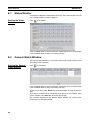
Status Monitor . . . . . . . . . . . . . . . . . . . . . . . . . . . . . . . . . . . . . . . . . . . . . . . . . . . . . . . . . . . .
General Watch Window . . . . . . . . . . . . . . . . . . . . . . . . . . . . . . . . . . . . . . . . . . . . . . . . . . . . .
64
64
SECTION 9
Operation . . . . . . . . . . . . . . . . . . . . . . . . . . . . . . . . . . . . . . . . .
65
9-1
9-2
9-3
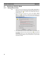
Switching to Monitor Mode . . . . . . . . . . . . . . . . . . . . . . . . . . . . . . . . . . . . . . . . . . . . . . . . .
Test Run . . . . . . . . . . . . . . . . . . . . . . . . . . . . . . . . . . . . . . . . . . . . . . . . . . . . . . . . . . . . . . . . .
Debugging the Program . . . . . . . . . . . . . . . . . . . . . . . . . . . . . . . . . . . . . . . . . . . . . . . . . . . . .
66
67
69
SECTION 10
Data Traces . . . . . . . . . . . . . . . . . . . . . . . . . . . . . . . . . . . . . . .
73
10-1 Data Traces . . . . . . . . . . . . . . . . . . . . . . . . . . . . . . . . . . . . . . . . . . . . . . . . . . . . . . . . . . . . . .
74
SECTION 11
Backup and Restore . . . . . . . . . . . . . . . . . . . . . . . . . . . . . . . .
77
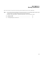
11-1 Backup from MC . . . . . . . . . . . . . . . . . . . . . . . . . . . . . . . . . . . . . . . . . . . . . . . . . . . . . . . . . .
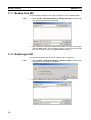
11-2 Restoring to MC . . . . . . . . . . . . . . . . . . . . . . . . . . . . . . . . . . . . . . . . . . . . . . . . . . . . . . . . . .
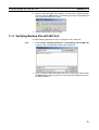
11-3 Verifying Backup File with MC Unit . . . . . . . . . . . . . . . . . . . . . . . . . . . . . . . . . . . . . . . . . .
78
78
79
SECTION 12
Read Protection. . . . . . . . . . . . . . . . . . . . . . . . . . . . . . . . . . . .
81
12-1
12-2
12-3
12-4
viii
43
Saving a Project . . . . . . . . . . . . . . . . . . . . . . . . . . . . . . . . . . . . . . . . . . . . . . . . . . . . . . . . . . .
Reading a Project. . . . . . . . . . . . . . . . . . . . . . . . . . . . . . . . . . . . . . . . . . . . . . . . . . . . . . . . . .
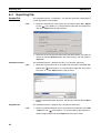
Importing Files . . . . . . . . . . . . . . . . . . . . . . . . . . . . . . . . . . . . . . . . . . . . . . . . . . . . . . . . . . .
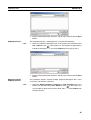
Exporting File . . . . . . . . . . . . . . . . . . . . . . . . . . . . . . . . . . . . . . . . . . . . . . . . . . . . . . . . . . . .
Read Protection . . . . . . . . . . . . . . . . . . . . . . . . . . . . . . . . . . . . . . . . . . . . . . . . . . . . . . . . . . .
Setting and Changing Passwords. . . . . . . . . . . . . . . . . . . . . . . . . . . . . . . . . . . . . . . . . . . . . .
Setting and Releasing Protection . . . . . . . . . . . . . . . . . . . . . . . . . . . . . . . . . . . . . . . . . . . . . .
Switching the User. . . . . . . . . . . . . . . . . . . . . . . . . . . . . . . . . . . . . . . . . . . . . . . . . . . . . . . . .
82
83
85
86
TABLE OF CONTENTS
SECTION 13
Printing . . . . . . . . . . . . . . . . . . . . . . . . . . . . . . . . . . . . . . . . . .
87
13-1 Printing . . . . . . . . . . . . . . . . . . . . . . . . . . . . . . . . . . . . . . . . . . . . . . . . . . . . . . . . . . . . . . . . .
88
SECTION 14
Error Log. . . . . . . . . . . . . . . . . . . . . . . . . . . . . . . . . . . . . . . . .
91
14-1 Error Log . . . . . . . . . . . . . . . . . . . . . . . . . . . . . . . . . . . . . . . . . . . . . . . . . . . . . . . . . . . . . . . .
14-2 Error Codes . . . . . . . . . . . . . . . . . . . . . . . . . . . . . . . . . . . . . . . . . . . . . . . . . . . . . . . . . . . . . .
92
92
SECTION 15
Troubleshooting . . . . . . . . . . . . . . . . . . . . . . . . . . . . . . . . . . .
93
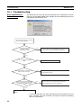
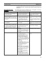
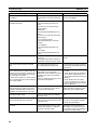
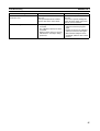
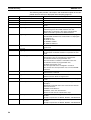
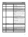
15-1 Troubleshooting . . . . . . . . . . . . . . . . . . . . . . . . . . . . . . . . . . . . . . . . . . . . . . . . . . . . . . . . . . .
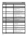
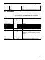
15-2 Error Codes . . . . . . . . . . . . . . . . . . . . . . . . . . . . . . . . . . . . . . . . . . . . . . . . . . . . . . . . . . . . . .
94
101
Revision History . . . . . . . . . . . . . . . . . . . . . . . . . . . . . . . . . . . 115
ix
TABLE OF CONTENTS
x
About this Manual:
This manual provides information required to use the CX-Motion-MCH software, including specifications and operating methods. The CX-Motion-MCH runs on Windows 2000, XP, Vista, or 7 and is used
to set data used by CS1W-MCH71 and CJ1W-MCH71 Motion Control Units (also referred to as MC
Units), create the required programs, and monitor the MC Unit’s operating status.
Please read this manual carefully and be sure you understand the information provided before
attempting to use the CX-Motion-MCH. Be sure to read the precautions provided in the following section.
Please read the MC Unit Operation Manual carefully and be sure you understand the information provided before setting up or using an application for a Motion Control Unit.
Name
Contents
SYSMAC CX-Motion-MCH
Operation Manual
SYSMAC CS1W/CJ1WMCH71
Motion Control Unit
Operation Manual
Describes the specifications and operating procedures for
the CX-Motion-MCH.
Describes the installation and operation of the CS1W/
CJ1W-MCH71 Motion Control Unit.
Cat. No.
(suffixes omitted)
W448 (this manual)
W435
For details on procedures for installing the CX-Motion-MCH from the CX-One FA Integrated Tool Package, refer to the CX-One Setup Manual provided with CX-One.
Cat. No.
W463
Model
CXONE-AL@@CV4/AL@@D-V4
Name
CX-One Setup Manual
Contents
Installation and overview of CX-One FA
Integrated Tool Package.
xi
Precautions provides general precautions for using the CX-Motion-MCH, Programmable Controller,
and related devices.
Section 1 provides an overview of the CX-Motion-MCH, and describes the functions and system configuration required to operate the CX-Motion-MCH. Be sure to read this section before using the CXMotion MCH.
Section 2 provides information on installing the CX-Motion-MCH and CX-Server, and connecting to
the PLC.
Section 3 describes each of the windows and basic operations.
Section 4 provides information on creating projects and adding MC Units, tasks, axes, programs, subprograms, and CAM tables.
Section 5 describes the operations used to edit data.
Section 6 describes the operations used to save and read new projects.
Section 7 describes the operations used to transfer or compare data between the personal computer
and Motion Control Unit/Servo Driver, and to write data transferred to the Motion Control Unit to the
Motion Control Unit's flash memory.
Section 8 provides information on monitoring the MC Units. The MC Unit's communications status,
error status, and axis's present position and status are displayed in the Monitor Windows.
Section 9 describes various operations on the axes of the MC Unit, including test run operations and
program debugging.
Section 10 describes the data trace function.
Section 11 describes the operations used to back up data from MC Units and restore data to MC
Units.
Section 12 describes the operations used to set and release protection on programs or cam data in
MC Units, set and change primary and secondary passwords, and switch the user.
Section 13 describes the operations used to print project data.
Section 14 provides information on the error log generated by the MC Unit.
Section 15 provides information on the troubleshooting methods for the MC Unit.
xii
Read and Understand this Manual
Please read and understand this manual before using the product. Please consult your OMRON
representative if you have any questions or comments.
Warranty and Limitations of Liability
WARRANTY
(1) The warranty period for the Software is one year from either the date of purchase or the date on which
the Software is delivered to the specified location.
(2) If the User discovers a defect in the Software (i.e., substantial non-conformity with the manual), and
returns it to OMRON within the above warranty period, OMRON will replace the Software without charge
by offering media or downloading services from the Internet. And if the User discovers a defect in the
media which is attributable to OMRON and returns the Software to OMRON within the above warranty
period, OMRON will replace the defective media without charge. If OMRON is unable to replace the
defective media or correct the Software, the liability of OMRON and the User's remedy shall be limited to
a refund of the license fee paid to OMRON for the Software.
LIMITATIONS OF LIABILITY
(1) THE ABOVE WARRANTY SHALL CONSTITUTE THE USER'S SOLE AND EXCLUSIVE REMEDIES
AGAINST OMRON AND THERE ARE NO OTHER WARRANTIES, EXPRESSED OR IMPLIED,
INCLUDING BUT NOT LIMITED TO, WARRANTY OF MERCHANTABILITY OR FITNESS FOR A
PARTICULAR PURPOSE. IN NO EVENT WILL OMRON BE LIABLE FOR ANY LOST PROFITS OR
OTHER INDIRECT, INCIDENTAL, SPECIAL, OR CONSEQUENTIAL DAMAGES ARISING OUT OF
USE OF THE SOFTWARE.
(2) OMRON SHALL ASSUME NO LIABILITY FOR DEFECTS IN THE SOFTWARE BASED ON
MODIFICATION OR ALTERATION OF THE SOFTWARE BY THE USER OR ANY THIRD PARTY.
(3) OMRON SHALL ASSUME NO LIABILITY FOR SOFTWARE DEVELOPED BY THE USER OR ANY
THIRD PARTY BASED ON THE SOFTWARE OR ANY CONSEQUENCE THEREOF.
Application Considerations
SUITABILITY FOR USE
THE USER SHALL NOT USE THE SOFTWARE FOR A PURPOSE THAT IS NOT DESCRIBED IN THE
ATTACHED USER MANUAL.
xiii
Disclaimers
CHANGE IN SPECIFICATIONS
The software specifications and accessories may be changed at any time based on improvements or for
other reasons.
EXTENT OF SERVICE
The license fee of the Software does not include service costs, such as dispatching technical staff.
ERRORS AND OMISSIONS
The information in this manual has been carefully checked and is believed to be accurate; however, no
responsibility is assumed for clerical, typographical, or proofreading errors, or omissions.
xiv
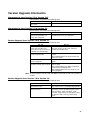
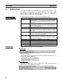
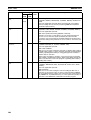
Version Upgrade Information
Improvements from Version 2.2 to Version 2.24
New functions are listed in the following table.
Ver. 2.2
Applicable OS: Windows 2000,
XP, or Vista
Ver. 2.24
Applicable OS: Windows 2000, XP, Vista, or 7
Improvements from Version 2.1 to Version 2.2
New functions are listed in the following table.
Ver. 2.1
Motion Control Units in CS/CJseries PLCs (excluding CJ2
PLCs) were supported.
Ver. 2.2
Motion Control Units in CS/CJ-series PLCs
(including CJ2 PLCs) are supported.
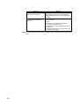
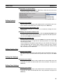
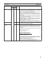
Version Upgrade from Version 2.0 to Version 2.1
New functions are listed in the following table.
Ver. 2.0
The CX-Motion-MCH could not
backup data from MC Units,
restore data to MC Units and verify backup files with MC Units.
The CX-Motion-MCH could not
provide read protection.
The CX-Motion-MCH could not
search in programs.
The CX-Motion-MCH could compare data with MC Units in detail.
Ver. 2.1
The CX-Motion-MCH can execute Backup from
MC Units, Restore to MC Units and Verify
backup files with MC Units.
The CX-Motion-MCH can set/release Read Protection.
The CX-Motion-MCH can set passwords and
switch user status.
The CX-Motion-MCH can find words in all programs.
The CX-Motion-MCH can compare data with MC
Units in detail.
The CX-Motion-MCH can display comparison
results in Overview/Detail View.
The CX-Motion-MCH can save results of comparing programs.
Note All new functions can be used with Motion Control Units with unit version 3.1
or later.
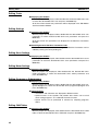
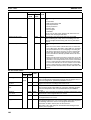
Version Upgrade from Version 1.0 to Version 2.0
New functions are listed in the following table.
Ver. 1.0
The CX-Motion-MCH could not
execute data traces.
The CX-Motion-MCH could not
execute test runs.
Ver. 2.0
The CX-Motion-MCH can execute data traces.
The results of a trace are displayed graphically.
The CX-Motion-MCH can execute the test run
operations, such as the following: Servo locks,
JOG operations, STEP operations, origin
searches, origin returns, forced origins, setting
an absolute origin, teaching, and resetting
errors.
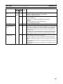
xv
Ver. 1.0
The CX-Motion-MCH could not
execute motion programs.
The CX-Motion-MCH could be
used to set only the previous
parameters.
Ver. 2.0
The CX-Motion-MCH can execute motion programs. Motion programs can be debugged by
setting break points and by using single step
execution.
New parameters have been added to use the following functions.
• Zones
• A setting for the number of the parallel
branches in each motion task
• Establishing the origin using the present position preset
• Changing the motor to Servo OFF state using
an external input signal.
Note All new functions can be used in Motion Control Units with unit version 3.0 or
later.
xvi
PRECAUTIONS
This section provides general precautions for using the CX-Motion-MCH software package.
The information contained in this section is important for the safe and reliable application of the CX-Motion-MCH.
You must read this section and understand the information contained before attempting to set up or operate the CXMotion-MCH.
1
2
3
4
5
Intended Audience . . . . . . . . . . . . . . . . . . . . . . . . . . . . . . . . . . . . . . . . . . . . .
General Precautions . . . . . . . . . . . . . . . . . . . . . . . . . . . . . . . . . . . . . . . . . . . .
Safety Precautions. . . . . . . . . . . . . . . . . . . . . . . . . . . . . . . . . . . . . . . . . . . . . .
Operating Environment Precautions . . . . . . . . . . . . . . . . . . . . . . . . . . . . . . . .
Application Precautions . . . . . . . . . . . . . . . . . . . . . . . . . . . . . . . . . . . . . . . . .
xviii
xviii
xviii
xix
xix
xvii
1
Intended Audience
1
Intended Audience
This manual is intended for the following personnel, who must also have
knowledge of electrical systems (an electrical engineer or the equivalent).
• Personnel in charge of installing FA systems.
• Personnel in charge of designing FA systems.
• Personnel in charge of managing FA systems and facilities.
2
General Precautions
The user must operate the product according to the performance specifications described in the operation manuals.
Before using the product under conditions which are not described in the
manual or applying the product to nuclear control systems, railroad systems,
aviation systems, vehicles, combustion systems, medical equipment, amusement machines, safety equipment, and other systems, machines, and equipment that may have a serious influence on lives and property if used
improperly, consult your OMRON representative.
Make sure that the ratings and performance characteristics of the product are
sufficient for the systems, machines, and equipment, and be sure to provide
the systems, machines, and equipment with double safety mechanisms.
This manual provides information for programming and operating the Unit. Be
sure to read this manual before attempting to use the Unit and keep this manual close at hand for reference during operation.
!WARNING It is extremely important that the CX-Motion-MCH and related devices be
used for the specified purpose and under the specified conditions, especially
in applications that can directly or indirectly affect human life. You must consult with your OMRON representative before applying Motion Control Units
and related devices to the above-mentioned applications.
3
Safety Precautions
!WARNING Do not attempt to take any Unit apart while the power is being supplied. Doing
so may result in electric shock.
!WARNING Never touch any of the terminals while power is being supplied. Doing so may
result in serious electric shock.
!WARNING Always back up programs, parameter data, position data, or cam data to the
flash memory after it has been transferred to the Motion Control Unit. If transferred data is not backed up in flash memory, the previous settings may be
used the next time the power is turned ON, resulting in a malfunction.
!Caution Check that the axis number is correct before operating an axis from the CXMotion-MCH.
!Caution Confirm safety at the destination node before transferring parameters or other
data to another node. Doing either of these without confirming safety may
result in injury.
xviii
Operating Environment Precautions
4
!Caution Do not save data (i.e., do not write data to flash memory) while the motion
program is being executed or the motor is operating. Unexpected operation
may result.
4
Operating Environment Precautions
!Caution Do not operate the MC Unit in the following locations:
• Locations subject to direct sunlight.
• Locations subject to temperatures or humidity outside the range specified
in the specifications.
• Locations subject to condensation as the result of severe changes in temperature.
• Locations subject to corrosive or flammable gases.
• Locations subject to dust (especially iron dust) or salts.
• Locations subject to exposure to water, oil, or chemicals.
• Locations subject to shock or vibration.
!Caution Take appropriate and sufficient countermeasures when installing the MC Unit
in the following locations:
• Locations subject to static electricity or other forms of noise.
• Locations subject to strong electromagnetic fields.
• Locations subject to possible exposure to radioactivity.
• Locations close to power supplies.
5
Application Precautions
Observe the following precautions when using the CX-Motion-MCH.
• Confirm that the correct unit number is specified for the destination node
before transferring parameters or other data to the Motion Control Unit.
• Confirm that programs, set parameters, and position data operate properly before using them in actual applications.
• Do not turn OFF the power to the Unit while writing to flash memory.
Doing so may result in damage to the flash memory.
• After replacing an MC Unit, restart operation only after saving the
required parameters, position data, and other data in the MC Unit.
• After transferring system parameters, servo parameters, programs, position data, or cam data to the MC Unit, always save the data to flash memory in the MC Unit before turning OFF the power supply using either the
Support Software or a command from the CPU Unit. If data is transferred
to the MC Unit without saving it to flash memory, the data will exist only in
S-RAM in the MC Unit and will thus be lost when the power supply to the
MC Unit is turned OFF.
• After transferring system parameters to the MC Unit, always save them in
flash memory and then either cycle the power supply to the MC Unit or
restart the MC Unit as a CPU Bus Unit from the CPU Unit. Some system
parameters will not be updated if the MC Unit is not restarted.
xix
5
Application Precautions
• Confirm that no adverse effect will occur in the system before attempting
any of the following. Not doing so may result in an unexpected operation.
• Changing the operating mode of the PLC (including changing the Startup Mode).
• Force-setting/force-resetting any bit in memory.
• Changing the present value of any word or any set value in memory.
• Do not turn OFF the power to the personal computer while installing or
uninstalling CX-Motion-MCH. Doing so may result in corrupted data in the
personal computer.
xx
SECTION 1
Overview of the CX-Motion MCH
This section provides an overview of the CX-Motion-MCH, and describes the functions and system configuration required
to operate the CX-Motion-MCH. Be sure to read this section before using the CX-Motion MCH.
1-1
What is the CX-Motion-MCH?. . . . . . . . . . . . . . . . . . . . . . . . . . . . . . . . . . . .
2
1-2
System Configuration . . . . . . . . . . . . . . . . . . . . . . . . . . . . . . . . . . . . . . . . . . .
3
1-3
Function List . . . . . . . . . . . . . . . . . . . . . . . . . . . . . . . . . . . . . . . . . . . . . . . . . .
4
1-4
Operation Procedure . . . . . . . . . . . . . . . . . . . . . . . . . . . . . . . . . . . . . . . . . . . .
6
1
Section 1-1
What is the CX-Motion-MCH?
1-1
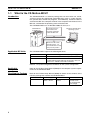
What is the CX-Motion-MCH?
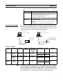
Introduction
The CX-Motion-MCH is a software package that can be used to set, create,
and print various data required to control MC Units (such as system parameters, position data, motion task programs, and CAM data), transfer the data to
and from the MC Unit, compare the data in the computer with the data in the
MC Unit, and monitor the operating status of the MC Unit.
The CX-Motion-MCH runs on Windows 2000, XP, Vista, or 7.
CS1W-MCH71
CJ1W-MCH71
Set and transfer the
various data and
programs required to
control the MC Unit.
Computer with Windows
operating system
Monitor the MC Unit's
operating status, e.g.,
error information or each
axis' present position.
Applicable MC Units
The CX-Motion-MCH supports the following MC Units.
Model number
CS1W-MCH71
CJ1W-MCH71
Applicable PLCs
Recent versions of CS1 CPU Units (CS1@-CPU@@H)
CJ2 CPU Units
CJ1H/CJ1M CPU Units with unit version 2.0 or later, CPseries PLCs, and NSJ-series NSJ Controllers
Refer to 1-2 System Configuration for details on the system configuration.
Applicable
Computers
Refer to the CX-One Setup Manual (W463) for the computer system requirements for the CX-Motion-MCH.
Checking the Package
Refer to the CX-One Setup Manual (W463) for details on the contents of the
CX-One package that includes the CX-Motion-MCH.
Cat. No.
W463
2
Model
CXONE-AL@@CV4/AL@@D-V4
Manual name
CX-One Setup
Manual
Contents
Installation and
overview of CXOne FA Integrated
Tool Package.
Section 1-2
System Configuration
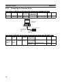
1-2
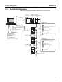
System Configuration
The system configuration for Motion Control Units is shown below.
Power
Supply Unit
CJ Series MC Unit
CPU Unit (CJ1W-MCH71)
Toolbus/
Host Link
External inputs
Forward rotation limit input signal
Reverse rotation limit input signal
CX-Motion-MCH
Editing/Transferring parameters
Monitoring
File management, etc.
Origin input signal
Origin proximity input signal
Servo Driver
CX-Programmer
Creating/Transferring
ladder program
Monitoring
File management, etc.
Interrupt input signal
24-V DC power supply for
interface
Servomotor
External inputs
Servo Driver
Forward rotation limit input signal
Reverse rotation limit input signal
Origin input signal
Servomotor
Origin proximity input signal
Interrupt input signal
Servo Driver
24-V DC power supply for
interface
MECHATROLINK-II
(30 axes max.)
3
Section 1-3
Function List
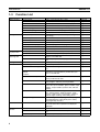
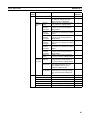
1-3
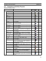
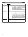
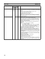
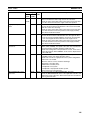
Function List
Group
Editing projects
Editing data
Function
Create project
Add/delete Motion Control Unit
Add/delete motion task
Add/delete axis
Add/delete program
Add/delete subprogram
Add/delete CAM table
Edit system parameters
Details
Used to create project files (*.mnh)
Used to add or delete MC Unit data in a project.
Used to add or delete motion tasks in a project.
Used to add or delete axes in a project.
Used to add or delete programs in a project.
Used to add or delete subprograms in a project
Used to add or delete CAM tables in a project.
Used to edit system parameters. (unit settings, tasks,
and settings)
Used to edit servo parameters.
Reference
page 30
page 31
page 32
page 33
page 34
page 35
page 35
page 40
Used to edit motor parameters.
Used to edit position data.
Used to edit programs or subprograms.
Used to edit CAM tables.
Used to edit symbols.
Used to save data as a project file (*.mnh).
Used to read a project file (*.mnh).
Used to import MC-Miel for MCH files, position data,
programs, and CAM data.
Used to export position data, programs, and CAM
data.
Used to print various project data.
Used to setup CPU Unit or MC Unit.
page 42
page 41
page 42
page 42
page 41
page 44
page 44
page 45
Communications setting
Used to make settings for communications with the
PLC.
page 54
Download
Upload
Compare
Write to flash memory
Used to download, compare, or upload system
parameters, servo parameters, position data, programs, and CAM data.
page 56
Used to write RAM data inside the MC Unit to flash
memory inside the MC Unit.
Used to display the error information, program number in progress, and axes’ present positions.
Used to display and change the MC Unit’s variables,
such as the system variables, global variables, input
variables, output variables, position data, and task
variables.
Used to execute the following operations: Servo
locks, JOG operations, STEP operations, origin
searches, origin returns, forced origins, setting an
absolute origin, teaching, and resetting errors.
Used to debug the motion program. Motion programs
can be debugged by setting break points and by
using single step execution.
Used to set the trigger conditions and trace objects.
The results of the trace operation are displayed
graphically.
Used to backup the MC Unit.
Used to restore the selected backup file to the MC
Unit.
Used to verify the backup file with the MC Unit.
page 60
Edit servo parameters
Saving and reading project files
Importing and
exporting data
Edit motor parameters
Edit position data
Edit program or subprogram
Edit CAM table
Edit symbol
Save project
Read project
Import
Export
Printing
Online
Print
Initial setting
Status monitor
General monitor
Test Run
Debug the Program
Data Trace
Data Trace
Backup and
Restore
Backup from MC
Restore to MC
Verify Backup file with MC Unit
4
page 42
page 48
page 88
page 54
page 64
page 64
page 67
page 69
page 74
page 78
page 78
page 79
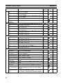
Section 1-3
Function List
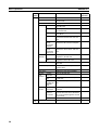
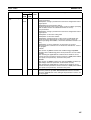
Group
Read Protection
Error
Function
Set/Change Password
Set/Release Protection
Switch User
Error log
Error information
Details
Used to set/change passwords for read protection.
Used to set/release protection on programs and cam
data and select data items that can be read through
the secondary password.
Used to switch the user.
Used to display the error log.
Used to display error code and error name.
Reference
page 83
page 85
page 86
page 92
page 92
5
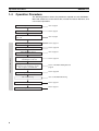
Section 1-4
Operation Procedure
1-4
Operation Procedure
The following flowchart shows the procedures required to install CX-MotionMCH and CX-Server, create various data, transfer that data to MC Units, and
use in actual operations.
Installing CX-Motion-MCH
Refer to page 8
Installing CX-Server
Refer to page 8
Connecting to Built-in RS-232C port on
CPU Unit
Refer to page 8
Starting CX-Motion-MCH
Refer to page 14
Creating a New Project
Refer to page 30
Adding MC Unit to Project
Refer to page 31
CX-Motion-MCH Basic Window
Adding Tasks, Axes, Programs,
and CAM Data to MC Unit
Editing/Transferring MC Unit's System
Parameters, Servo Parameters, Position
Data, Programs, and CAM Data
Writing to Flash Memory
MC Unit Monitoring
Saving Project
Quitting CX-Motion-MCH
6
Refer to page 33
Refer to SECTION 5 Editing Data and
page 56
Refer to page 60
Refer to SECTION 8 Monitoring
Refer to page 44
Refer to page 15
SECTION 2
Setup
This section provides information on installing the CX-Motion-MCH and CX-Server, and connecting to the PLC.
2-1
2-2
Installing and Uninstalling the Software. . . . . . . . . . . . . . . . . . . . . . . . . . . . .
8
Connecting to a PLC . . . . . . . . . . . . . . . . . . . . . . . . . . . . . . . . . . . . . . . . . . . .
8
2-2-1
Connecting to CS/CJ-series PLCs . . . . . . . . . . . . . . . . . . . . . . . . . .
8
2-2-2
Connecting to CP-series PLCs . . . . . . . . . . . . . . . . . . . . . . . . . . . . .
10
2-2-3
Connecting to CJ2 PLCs. . . . . . . . . . . . . . . . . . . . . . . . . . . . . . . . . .
11
7
Section 2-1
Installing and Uninstalling the Software
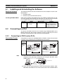
2-1
Installing and Uninstalling the Software
Required Software
The following software must be installed on the same computer to use the CXMotion-MCH.
1. CX-Motion-MCH
2. CX-Server (the communications driver)
Installing CX-Motion-MCH
Refer to the CX-One Setup Manual (Cat. No. W463) (supplied with the CXOne FA Integrated Tool Package) for information on how to install or uninstall
the CX-Motion-MCH from the CX-One FA Integrated Tool Package.
Cat. No.
W463
2-2
Model
Manual name
Contents
CXONE-AL@@C-V4/ CX-One Setup Man- An overview of the CXAL@@D-V4
ual
One FA Integrated Tool
Package and the CX-One
installation procedure
Connecting to a PLC
To transfer the project data that was created using CX-Motion-MCH to the
Motion Control Unit, the personal computer and PLC (CPU Unit) have to be
physically connected with a cable and also connected online.
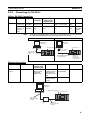
2-2-1
Connecting to CS/CJ-series PLCs
Connection Format
Using either the Host Link (SYSMAC WAY) or Toolbus, connect the personal
computer to the peripheral port or RS-232C port on the PLC.
Personal
computer
IBM PC/
AT or
compatible
Connecting to Peripheral Port
Connecting to RS-232C Port
9-pin
male
9-pin
female
PC-9801
BX
NEC
9-pin
male
Peripheral port
(10-pin female)
PC-9801
BX
NEC
CS1W-CN118 (0.1 m) (See note 1.)
CS1W-CN226 (2.0 m)
CS1W-CN626 (6.0 m)
CS1W-CN118 (See note 1.)
CS1W-CN226
CS1W-CN626
9-pin
10-pin
RS-232C port
(9-pin female)
XW2Z-200S-CV/200S-V (2.0 m)
XW2Z-500S-CV/500S-V (5.0 m)
XW2Z-200S-CV/-200S-V
XW2Z-500S-CV/-500S-V
female
Note
9-pin
female
9-pin
male
9-pin
female
9-pin
male
(1) The CS1W-CN118 cable is used as a relay cable to connect the personal
computer to the CPU Unit's peripheral port using the RS-232C cable
(model XW2Z-@@@@-@@) as shown below.
Peripheral Port
PC-9801
BX
NEC
RS-232C Cable
CS1W-CN118
(2) There are two network protocols (serial communications modes), SYSMAC WAY and Toolbus, that can be used to connect the CX-Motion-MCH
8
Section 2-2
Connecting to a PLC
to the PLC. The characteristics of the network protocols are as shown below.
Network type
Toolbus
SYSMAC WAY
(Host Link)
Connection Methods
Characteristics
Faster communications. If possible, use this network type.
• For CS/CJ Series, the baud rate on the peripherals can be
detected automatically, and be connected.
• Only 1 on 1 connection possible.
• For CX-Motion-MCH, it can also be connected to a modem.
Used for communications with general host computers.
• Slower than Toolbus.
• Not only 1 on 1 connection, but also 1-many connection
possible.
• Connecting to a modem and optical adaptor possible.
Use one of the following methods to connect the personal computer (CXMotion-MCH) and PLC (CPU Unit). It is also possible to connect the personal
computer to the port on the CS/CJ Series Serial Communications Unit. In that
case, the only network type that can be used is Host Link.
Connecting to Peripheral Port
Connecting to RS-232C Port
IBM PC/AT or compatible
IBM PC/AT or compatible
9-pin connector
9-pin connector
Peripheral port
on CPU Unit
Built-in RS-232C port
on CPU Unit or Serial
Communications Unit
9-pin connector
CS1W-CN118 (0.1 m)
CS1W-CN226 (2.0 m)
CS1W-CN626 (6.0 m)
XW2Z-200S-CV (2.0 m)
XW2Z-500S-CV (5.0 m)
Connection Cables
Unit
Port on Unit
Computer
Built-in
peripheral
port
Built-in RS232C port
(D-SUB, 9pin, female)
Serial
RS-232C port
Communi- (D-SUB, 9cations
pin, female)
Unit
IBM PC/AT
compatible
D-SUB, 9pin, male
Network type
Model number Length
(serial communications
mode)
SYSMAC WAY CS1W-CN226
2m
(Host Link)
CS1W-CN626
6m
IBM PC/AT
compatible
D-SUB, 9pin, male
SYSMAC WAY
(Host Link)
XW2Z-200S-CV 2 m
XW2Z-500S-CV 5 m
Uses anti-static
connector
IBM PC/AT
compatible
D-SUB, 9pin, male
SYSMAC WAY
(Host Link)
XW2Z-200S-CV 2 m
XW2Z-500S-CV 5 m
Uses anti-static
connector
CPU Unit
Note
Port on
computer
Remarks
---
When connecting the connectors of the above cables to the PLC's RS-232C
port, discharge any static build-up (e.g., by touching a grounded metal object)
before touching the connectors. Although XW2Z-@@@S-CV Cables use the
anti-static XM2S-0911-E Connector Hood (thus reducing the possibility of
static build-up), be sure to discharge any static as a safety precaution.
9
Section 2-2
Connecting to a PLC
2-2-2
Connecting to CP-series PLCs
Connecting to USB Port on CPU Unit with Commercially Available US Cable
Unit
CPU Unit
Port on Unit
Computer
USB port
IBM PC/AT
(B connector) compatible
Model number
Length Remarks
Serial communications mode
(network type)
USB port
USB
Commercially available 5 m
--(A connector)
USB 1.1 or 2.0 cable
max.
Port on
computer
IBM PC/AT or
compatible
USB port
CP-series CPU Unit
Commercially
available USB
cable
Peripheral
USB port
Connecting to RS-232C Port on Serial Communications Board with RS-232C Cable
Unit
Port on
Unit
CP1W-CIF01
Serial Communications
Board
RS-232C
port, Dsub 9-pin
female
10
Computer
Port on
Serial communiModel number
Length
computer
cations mode
(network type)
IBM PC/AT D-Sub, 9- Toolbus (PeriphXW2Z-200S-CV/500S-CV 2 m/5 m
compatible pin, male
eral) or SYSMAC
WAY (Host Link)
SYSMAC WAY
XW2Z-200S-V/500S-V
2 m/5 m
(Host Link)
Remarks
Uses antistatic connector
---
Section 2-2
Connecting to a PLC
2-2-3
Connecting to CJ2 PLCs
USB or RS-232C Connection
Unit
CPU Unit
Port on Unit
Computer
USB port
(B connector)
Built-in RS232C port, Dsub 9-pin
female
IBM PC/AT
compatible
IBM PC/AT
compatible
Note
Model number
Serial communications mode
(network type)
USB port
USB
Commercially available
(A connector)
USB 1.1 or 2.0 cable
D-sub 9-pin, Toolbus (See
XW2Z-200S-CV/500Smale
note.)
CV
Port on
computer
Length Remarks
5m
max.
2 m/
5m
--Uses
anti-static
connector
A Host Link (SYSMAC WAY) connection to an RS-232C port on the CPU Unit
or a Serial Communications Unit is not possible for CJ2 PLCs.
USB
RS-232C
IBM PC/AT or
compatible
IBM PC/AT or
compatible
Commercially
available USB
cable
CJ2 CPU Unit
CJ2 CPU Unit
USB port
D-sub connector
(9-pin male)
USB port
XW2Z-200S-CV/500S-CV
Connecting Cable
Serial port
(RS-232C):
D-sub connector
(9-pin female)
Ethernet Connection
Port on Unit
Built-in EtherNet/
IP port
Port on computer Serial communications mode
(network type)
Ethernet port
100Base-TX/
10Base-T (Recommended:
100Base-TX)
Model number
Commercially
available twisted
cable based on
EtherNet/IP standard
Commercially
available switching hub
Length
100 m (between
hub and node)
Remarks
---
---
IBM PC/AT or
compatible
Built-in EtherNet/IP port
CJ2 CPU Unit
100Base-TX
twisted-pair cable
(straight)
Switching
hub
100Base-TX
twisted-pair cable
(straight)
11
Connecting to a PLC
12
Section 2-2
SECTION 3
Basic Operations
This section describes each of the windows and basic operations.
3-1
Basic Operations . . . . . . . . . . . . . . . . . . . . . . . . . . . . . . . . . . . . . . . . . . . . . . .
14
3-2
Operations Listed by Purpose . . . . . . . . . . . . . . . . . . . . . . . . . . . . . . . . . . . . .
25
13
Section 3-1
Basic Operations
3-1
Basic Operations
Starting the CX-Motion-MCH
Starting the CX-Motion-MCH Using Start Special Application - Start with Settings Inherited from the I/O
Table Window Opened from the CX-Programmer That Was Installed from the CX-One
1,2,3...
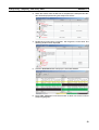
1. Right-click a Motion Control Unit in the I/O Table Window and select Start
Special Application - Start with Settings Inherited from the pop-up
menu.
2. The CX-Motion-MCH will be started, a new project will be created, and a
Motion Control Unit will be added automatically. The Motion Control Unit
model will be inherited as shown below.
14
Section 3-1
Basic Operations
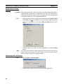
Starting the CX-Motion-MCH Using Start Special Application - Start Only from the I/O Table Window
Opened from the CX-Programmer That Was Installed from the CX-One
Right-click a Motion Control Unit in the I/O Table Window and select Start
Special Application - Start Only from the pop-up menu. The following window will be displayed.
Starting the CX-Motion-MCH from Windows Start Menu
Select Start - Programs - OMRON - CX-One - CX-Motion-MCH - CXMotion-MCH. The same window as when selecting Start Only will be displayed.
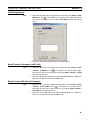
Quitting the CX-Motion-MCH
1,2,3...
1. Select File - Exit or click the
at the top right corner of the window. After
editing a project, if the project has not been saved, the following dialog box
will be displayed.
2. Click the Yes Button to save the changes made. Click the No Button if it is
not necessary to save the changes. Click the Cancel Button to return to
the Basic Window without quitting CX-Motion-MCH.
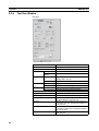
Main Menus
Main Menu
File
Edit
View
Insert
Online
Program
Debug
Tools
Contents
Used to create or save projects.
Used to edit the MC Unit’s data.
Used to display or hide the Toolbars, Windows, or the
Status Bar.
Used to insert an MC Unit, motion task, axis, program,
subprogram, or CAM table into a project.
Used to establish communications with the MC Unit.
Used to compile the program.
Used to debug the program.
Used to change the fonts or toolbar.
Keyboard
shortcut
Alt+F
Alt+E
Alt+V
Alt+I
Alt+O
Alt+P
Alt+D
Alt+T
15
Section 3-1
Basic Operations
Main Menu
Windows
Help
Main Menu Items
Contents
Used to change the arrangement of open windows.
Used to display help and version information.
The names and functions for all of the menus are given in the table below.
When an item is selected, the dialog box for that function is displayed. Follow
the instructions in the dialog box.
Main
menu
File
Item
New
Open
Close
Save
Save As
Import
Export
Print Preview
Print
Exit
16
Keyboard
shortcut
Alt+W
Alt+H
Contents
Keyboard
shortcut
Creates a new project file (*.mnh).
Ctrl+N
Opens an existing project file (*.mnh).
Ctrl+O
Closes the project file (*.mnh).
--Saves the active project file (*.mnh)
Ctrl+S
by overwriting the previous data.
Saves the active project data in a
--project file (*.mnh) with a new name.
Imports MC-Miel for MCH files, posi--tion data, motion programs, or CAM
data.
Exports position data, motion pro--grams, or CAM data.
Shows a print preview image.
--Prints project data.
Ctrl+P
Quits CX-Motion-MCH.
Alt+F4
Section 3-1
Basic Operations
Main
menu
Edit
Item
Undo
Redo
Cut
Copy
Paste
Delete
Select All
Find
Find In Programs
Replace
Go to
Edit
Contents
Keyboard
shortcut
Restores the previous data that was
edited in the parameter data, position
data, motion program, or CAM data
editing window.
Restores the edited data that was
undone in the parameter data, position data, motion program, or CAM
data editing window.
Cuts the data selected in the program
editing window.
Copies the data selected in the
parameter data, position data, motion
program, or CAM data editing window.
Ctrl+Z
Pastes the copied data in the parameter data, position data, motion program, or CAM data editing window.
Deletes an MC Unit, motion task,
axis, motion program, or CAM table.
Selects all of the data displayed in the
parameter data, position data, motion
program, or CAM data editing window.
Searches for text in the motion program, position data, or CAM data
editing window.
Searches for text in all motion programs.
Replaces text in the motion program,
position data, or CAM data editing
window.
Moves the cursor to the specified line
number in the motion program or
position data editing window.
Opens the editing window for parameter data, position data, motion program, or CAM data.
Ctrl+Y
Ctrl+X
Ctrl+C
Ctrl+V
Del
Ctrl+A
Ctrl+F
Ctrl+H
Ctrl+G
Ctrl+E
17
Section 3-1
Basic Operations
Main
menu
View
Item
Toolbar
Windows
18
Standard
Insert
Online
Views
Servo Settings
Program
Debug
Project
Workspace
Output Window
General
Watch Window
Debug
Watch Window
Status
Monitor
Test Run
Contents
Keyboard
shortcut
Displays/hides the Standard Toolbar.
Displays/hides the Insert Toolbar.
Displays/hides the Online Toolbar.
Displays/hides the View Toolbar.
Displays/hides the Servo Settings
Toolbar.
Displays/hides the Program Toolbar.
Displays/hides the Debug Toolbar.
Displays/hides the Project Workspace Window.
Displays/hides the Output Window.
-----------
Alt+1
Alt+2
Displays/hides the General Watch
Window.
Alt+3
Displays/hides the Debug Watch
Window.
Alt+4
Displays/hides the Status Monitor
Window.
Displays/hides the Test Run Window.
Alt+5
Alt+6
Section 3-1
Basic Operations
Main
menu
View
Insert
Item
Status Bar
Properties
Contents
Displays/hides the Status Bar.
Opens the Properties Window for a
PLC, MC Unit, motion task, axis,
motion program or CAM table.
Servo
All ConDisplays all of the parameters in the
Parame- stants
servo parameters editing window.
ters
Displays only the function selection
Function
constants in the servo parameters
Selection
editing window.
Constants
Gain
Displays only the gain-related conRelated
stants in the servo parameters editing
Constants
window.
Position
Displays only the position-related
Related
constants in the servo parameters
Constants
editing window.
Displays only the speed-related conSpeed
stants in the servo parameters editing
Related
window.
Constants
Torque
Displays only the torque-related conRelated
stants in the servo parameters editing
Constants
window.
Sequence
Displays only the sequence-related
Related
constants in the servo parameters
Constants
editing window.
Other Con- Displays only the other constants in
stants
the servo parameters editing window.
Show Modi- Displays only those parameters with
Servo
changed values from the default in
Parame- fied Only
the servo parameters editing window.
ter Value
Show DifDisplays only those parameters with
ferent Only values different between the computer and MC Unit in the servo
parameters editing window.
Show
Displays only those parameters with
Invalid Only invalid values (out-of-range settings)
in the servo parameters editing window.
MC
Inserts an MC Unit to the project.
Task
Inserts a motion task to the project.
Axis
Inserts an axis to the project.
Program
Inserts a program to the project.
Sub Program
Inserts a subprogram to the project.
CAM
Inserts a CAM table to the project.
Keyboard
shortcut
-----
-----
---
---
---
---
---
-----
---
---
-------------
19
Section 3-1
Basic Operations
Main
menu
Item
Online
Work Online
Monitor Mode
20
Keyboard
shortcut
Switches between online/offline.
Switches between normal mode and
monitor mode
Unit Information
Displays the Unit information.
Transfer
To MC
Transfers parameters and other data
to the MC Unit.
From MC
Transfers parameters and other data
from the MC Unit.
From Servo Transfers servo parameters from the
Servo Driver.
Compare
Compares parameters and data values between the MC Unit and computer.
Compares servo parameter values
Compare
Servo
between the MC Unit and computer.
Parameter
with MC
Compares servo parameter values
Compare
Servo
between the Servo Driver and comParameter puter.
with Servo
Batch
To All MC
Transfers parameters and other data
Transfer
altogether to the MC Unit.
From All
Transfers parameters and other data
MC
altogether from the MC Unit.
---
Write To Flash
Saves the MC Unit’s parameters and
other data.
---
Clear Memory
Initializes the MC Unit’s parameters
and other data.
Displays the MC Unit’s error log.
Displays the Data Trace Window.
Backs up the MC Unit.
---
Error Log
Data Trace
Backup
Backup
from MC
and
Restore
Restore to
MC
Verify
Backup file
with MC
Unit
Program
Contents
-----------
---
---
-----
---
Restores the selected backup file to
the MC Unit.
Verifies the backup file with the MC
Unit.
Read Pro- Set/Change Sets/changes the passwords for read
tection
Password
protection.
Sets/releases protection on programs
Set/
and cam data and selects data items
Release
that can be read through the secondProtection
ary password.
Switch User Switches the user.
Compile
Compiles the program.
F7
Section 3-1
Basic Operations
Main
menu
Debug
Item
Contents
Insert/Remove Break
Point
Remove All Break
Points
Go
Step Into
Inserts/removes a break point.
Removes all break points.
Debugs the program.
Debugs the program one step at a
time.
Stops debugging the program.
Debugging will stop one line before
the cursor.
Customizes the Toolbar.
Sets the font.
Closes all open editing windows.
Moves the focus to the next window.
Moves the focus to the previous window.
Stacks the open editing windows.
Horizontally tiles the open editing
windows.
Vertically tiles the open editing windows.
Stop
Run To Cursor
Tools
Customize
Font Options
Close All
Next Docked
Previous Docked
Windows
Cascade
Tile Horizontally
Tile Vertically
Help
Toolbars
Keyboard
shortcut
F9
Ctrl+Shift+
F9
F5
F11
Shift+F5
Ctrl+F10
------Alt+0
Alt+Shift+0
Help Contents
Displays the table of contents for
help.
Search for Help On
Displays the help search topics.
Command Reference
Displays the command reference
help.
Parameter Reference
Displays the parameter reference
help.
Value Reference
Displays the value reference help.
Troubleshooting
Displays the troubleshooting help.
Online Registration
Connects to the OMRON online user
registration.
About CX-Motion-MCH Displays the version information.
------F1
-------------
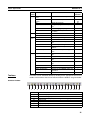
Functions can be executed directly by clicking on the appropriate icon on the
toolbar. The functions that can be executed from the toolbars are given below.
Standard Toolbar
1
2
3
Number
(1)
(2)
(3)
(4)
(5)
(6)
(7)
4
5
6
7
8
9 10 11 12
13 14 15 16 17 18
Function
Create a new project.
Open an existing project.
Save the active project by overwriting the existing project file.
Export to file.
Import from file.
Display the print preview.
Print
21
Section 3-1
Basic Operations
Number
(8)
(9)
(10)
(11)
(12)
(13)
(14)
(15)
(16)
(17)
(18)
Function
Cut
Copy
Paste
Undo
Redo
Find
Find In Programs
Replace
Edit
Display CX-Motion-MCH information.
Display the table of contents for help.
View Toolbar
1
2 3 4 5 6
Number
(1)
(2)
(3)
(4)
(5)
(6)
Function
Display/hide the Project Workspace Window.
Display/hide the Output Window.
Display/hide the General Watch Window.
Display/hide the Debug Watch Window.
Display/hide the Status Monitor Window.
Display the Properties Window.
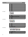
Insert Toolbar
1
2
Number
(1)
(2)
(3)
(4)
(5)
(6)
3
4
5
6
Function
Insert an MC Unit.
Insert a motion task.
Insert an axis.
Insert a program.
Insert a subprogram.
Insert a CAM table.
Online Toolbar
1
2 3 4 5 6 7 8 9 10 11 12 13 14 15
Number
(1)
(2)
(3)
22
Function
Transfer to MC Unit.
Transfer from MC Unit.
Transfer from Servo Driver.
Section 3-1
Basic Operations
Number
(4)
(5)
(6)
(7)
(8)
(9)
(10)
(11)
(12)
(13)
(14)
(15)
Function
Compare with MC Unit.
Compare servo parameters with MC Unit.
Compare servo parameters with Servo Driver.
Batch transfer to MC Unit.
Batch transfer from MC Unit.
Save in flash memory.
Clear memory.
Display error log.
Display the Data Trace Window.
Delete
Switch between online/offline.
Switch between normal mode and monitor mode.
Program Toolbar
1
2 3
Number
(1)
(2)
(3)
Function
Compile the program.
Insert/remove a break point.
Remove all break points.
Debug Toolbar
1
2 3 4 5 6 7
Number
(1)
(2)
(3)
(4)
(5)
(6)
Function
Select the task number.
Display/hide the Test Run Window.
Debug the program.
Stop debugging the program.
Debug the program one step at a time.
Debugging will stop one line before the cursor.
(7)
Stop all axes.
Servo Settings Toolbar
1
2
Number
(1)
(2)
(3)
3
Function
Show Modified Only
Show Different Only
Show Invalid Only
23
Section 3-1
Basic Operations
Status Bar
The following information is displayed on the status bar.
2
1
Number
(1)
(2)
(3)
(4)
(5)
(6)
3
4
5
6
Function
Displays messages regarding the status of data being edited or transferred.
Displays a bar graph showing the progress of a data transfer.
Displays the cursor position in the program editing window.
Indicates the online/offline status.
Indicates the keyboard Caps Lock status.
Indicates the keyboard Num Lock status.
Help
Displaying the Help Contents
1,2,3...
1. Select Help - Help Contents. The table of contents for help will be displayed.
2. Click a topic to display information. The contents related to that topic will
be displayed.
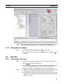
Displaying CX-MotionMCH Version Information
24
Select Help - About CX-Motion-MCH. The CX-Motion-MCH version information will be displayed.
Section 3-2
Operations Listed by Purpose
3-2
Operations Listed by Purpose
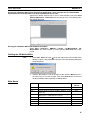
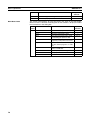
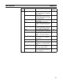
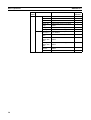
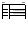
Operations Listed by Purpose
Function (Purpose)
Operation
Keyboard Toolbar
shortcut
icon
Page
Project
Creating a new project Select File - New.
Ctrl+N
30
Opening a project
Ctrl+O
44
Ctrl+S
44
Select File - Open.
Saving a project (over- Select File - Save.
writing)
Saving a project with a Select File - Save As.
different name
Close a project
Select File - Close.
Quitting CX-MotionMCH
Adding an MC Unit to
the project
Importing a file created by MC-Miel for
MCH
Importing position
data from a file
Exporting position
data to a file
Importing a program
from a file
---
---
44
---
---
---
Select File - Exit.
---
---
15
Select the PLC and select Insert - MC or right-click and
select Insert MC.
Select the PLC and select File - Import or right-click and
select Import From Miel.
---
31
---
45
---
45
---
48
---
46
---
48
---
46
---
49
---
47
---
50
---
22
---
32
Del
32
---
33
Del
34
---
34
Del
35
---
35
Select the position data and select File - Import or rightclick and select Import.
Select the position data and select File - Export or rightclick and select Export.
Select Motion Programs, Programs, or the program and
select File - Import or right-click and select Import Program or Import.
Exporting a program
Select the program and select File - Export or right-click
to a file
and select Export.
Importing a subproSelect Motion Programs, Programs or the sub program
gram from a file
and select File - Import or right-click and select Import
Sub Program or Import.
Exporting a subproSelect the subprogram and select File - Export or rightgram to a file
click and select Export.
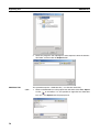
Importing a CAM table Select a CAM or CAM table and select File - Import or
from a file
right-click and select Import CAM or Import.
Exporting a CAM table Select the CAM table and select File - Export or right-click
to a file
and select Export.
Displaying properties Select a PLC, MC Unit, task, Servo Driver, program, subprogram, or CAM table and select View - Properties or
right-click and select Properties.
Adding a motion task Select Tasks and select Insert - Task or right-click and
select Insert Task.
Deleting a motion task Select Tasks and select Edit - Delete or right-click and
select Delete.
Adding an axis
Select Axes and select Insert - Axis or right-click and
select Insert Axis.
Deleting an axis
Select the axis and select Edit - Delete or right-click and
select Delete.
Adding a program
Select Motion Programs or Programs and select Insert Program or right-click and select Insert Program.
Deleting a program
Select the program and select Edit - Delete or right-click
and select Delete.
Adding a subprogram Select Motion Programs or Sub Programs and select
Insert - Sub Program or right-click and select Insert Sub
Program.
25
Section 3-2
Operations Listed by Purpose
Function (Purpose)
Operation
Deleting a subprogram
Adding a CAM table
Select the subprogram and select Edit - Delete or rightclick and select Delete.
Select CAM and select Insert - CAM or right-click and
select Insert CAM.
Deleting a CAM table Select the CAM table and select Edit - Delete or right-click
and select Delete.
Displaying a print pre- Select File - Print Preview.
view
Printing parameters or Select File - Print.
programs
Editing parameters
Editing Unit Parame- Select Unit Settings and select Edit - Edit, right-click and
ters
select Edit, or double-click.
Editing task parame- Select the task and select Edit - Edit, right-click and select
ters
Edit, or double-click.
Editing axis parameSelect settings and select Edit - Edit, right-click and select
ters
Edit, or double-click.
Editing servo parame- Select servo settings and select Edit - Edit, right-click and
ters
select Edit, or double-click.
Editing motor parame- Select motor settings and select Edit - Edit, right-click and
ters
select Edit, or double-click.
Editing data
Editing position data
Select Position Data and select Edit - Edit, right-click and
select Edit, or double-click.
Editing a program
Select Programs and select Edit - Edit, right-click and
select Edit, or double-click.
Editing a subprogram
Compiling a program
Editing a CAM table
Online operations
Starting communications with PLC
Setting communications with PLC
Transferring selected
data to the MC Unit
Transferring selected
data from the MC Unit
Transferring data to all
the MC Units
Transferring data from
all the MC Units
Transferring from the
Servo Driver
Comparing parameters or data with MC
Unit
Comparing servo
parameters with MC
Unit
26
Keyboard Toolbar
shortcut
icon
Page
Del
36
---
37
Del
38
---
21
Ctrl+P
92
Ctrl+E
41
Ctrl+E
42
Ctrl+E
42
Ctrl+E
42
Ctrl+E
42
Ctrl+E
41
Ctrl+E
42
Select Sub Programs and select Edit - Edit, right-click and Ctrl+E
select Edit, or double-click.
Select the program or subprogram and select Edit - Com- F7
pile or right-click and select Compile.
Select the CAM table and select Edit - Edit, right-click and Ctrl+E
select Edit, or double-click.
42
Select the PLC and select Online - Work Online or rightclick and select Work Online.
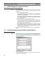
Select the PLC and select View - Properties or right-click
and select Properties.
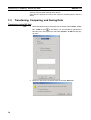
Select the parameters or data to be transferred and select
Online - Transfer - To MC.
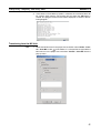
Select the parameters or data to be transferred and select
Online - Transfer - From MC.
Select the PLC and select Online - Batch Transfer - To
All MC.
Select the PLC and select Online - Batch Transfer - From
All MC.
Select Servo Settings and select Online - Transfer - From
Servo or right-click and select Transfer - From Servo.
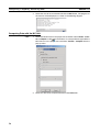
Select the MC Unit to be compared and select Online Transfer - Compare or right-click and select Transfer Compare.
Select the Servo Settings and select Online - Transfer Compare Servo Parameter with MC or right-click and
select Transfer - Compare Servo Parameter with MC.
Ctrl+W
55
---
54
---
56
---
57
---
61
---
61
---
---
---
58
---
---
23
42
Section 3-2
Operations Listed by Purpose
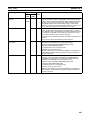
Function (Purpose)
Operation
Keyboard Toolbar
shortcut
icon
Page
Comparing servo
parameters with Servo
Driver
Initializing memory
Select Servo Settings and select Online - Transfer - Com- --pare Servo Parameter with Servo or right-click and select
Transfer - Compare Servo Parameter with Servo.
Select the MC Unit and select Online - Clear Memory.
---
---
Writing to flash memory
Monitoring the MC
Unit’s status or errors
Monitoring variables
Select the MC Unit and select Online - Write To Flash.
60
Displaying error log
Debugging the program
Executing Test Run
operations, such as
JOG operations
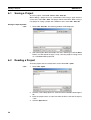
Tracing data
Backing up the MC
Unit
Restoring a backup
file to the MC Unit
Verifying a backup file
with the MC Unit
Setting and changing
passwords for protection
Setting and releasing
protection
Switching user
Displaying settings
Displaying/hiding Toolbar
Displaying/hiding the
Project Workspace
Displaying/hiding the
Output Window
61
---
Select the MC Unit and select View - Windows - Status
Alt+5
Monitor.
Select the MC Unit and select View - Windows - General Alt+3
Watch Window.
Select the MC Unit and select Online - Error Log.
---
64
64
92
Select the MC Unit and select Online - Monitor Mode.
Select the MC Unit and select Online - Monitor Mode.
Select the MC Unit and select Online - Data Trace.
Select the MC Unit and select Online - Backup and
Restore - Backup from MC.
Select the MC Unit and select Online - Backup and
Restore - Restore to MC.
Select the MC Unit and select Online - Backup and
Restore - Verify Backup files with MC.
Select the MC Unit and select Online - Read Protection Set/Change Password.
Select the MC Unit and select Online - Read Protection Set/Release Protection.
Select the MC Unit and select Online - Read Protection Switch User.
78
---
78
---
79
---
83
---
85
---
86
---
18
Select View - ToolBar and select Standard, Insert,
Online, View or Servo Settings.
Select View - Windows - Project Workspace.
Alt+1
22
Select View - Windows - Output Window.
Alt+2
22
Displaying/hiding Sta- Select View - Status Bar.
tus Bar
Displaying/hiding the Select View - Window - Debug Watch Window.
Debug Watch Window
Displaying/hiding the Select View - Window - Test Run.
Test Run
---
---
---
---
19
Alt+4
69
Alt+6
67
Help
Displaying the MC
Unit’s model and version
Displaying help
Displaying the CXMotion-MCH
Select the MC Unit and select Online - Unit Information.
F1
Select Help - Help Contents.
F1
Select Help - Search for Help On.
Select Help - About CX-Motion-MCH.
F1
---
---
60
24
---
21
24
27
Operations Listed by Purpose
28
Section 3-2
SECTION 4
Creating Projects
This section provides information on creating projects and adding MC Units, tasks, axes, programs, subprograms, and
CAM tables.
4-1
Creating a New Project . . . . . . . . . . . . . . . . . . . . . . . . . . . . . . . . . . . . . . . . . .
30
4-2
Adding and Deleting MC Units . . . . . . . . . . . . . . . . . . . . . . . . . . . . . . . . . . .
31
4-3
Adding and Deleting Tasks . . . . . . . . . . . . . . . . . . . . . . . . . . . . . . . . . . . . . . .
32
4-4
Adding and Deleting Axes . . . . . . . . . . . . . . . . . . . . . . . . . . . . . . . . . . . . . . .
33
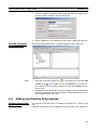
4-5
Adding and Deleting Programs. . . . . . . . . . . . . . . . . . . . . . . . . . . . . . . . . . . .
34
4-6
Adding and Deleting Subprograms. . . . . . . . . . . . . . . . . . . . . . . . . . . . . . . . .
35
4-7
Adding and Deleting CAMs . . . . . . . . . . . . . . . . . . . . . . . . . . . . . . . . . . . . . .
37
29
Section 4-1
Creating a New Project
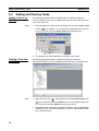
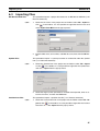
4-1
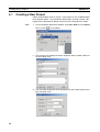
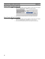
Creating a New Project
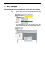
Follow the procedure below to create a new project on the CX-Motion-MCH
Basic Window. When a new CX-Motion-MCH project is being created, a dialog box will be displayed for adding an MC Unit after setting the PLC model.
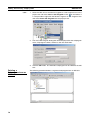
1,2,3...
1. On the CX-Motion-MCH Basic Window, select File - New, press the Ctrl+N
Keys, or click
in the toolbar.
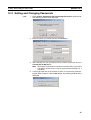
2. The Change PLC Dialog Box will be displayed. Set the model number of
the PLC being used.
3. The Insert MC Dialog Box will be displayed. Set the model number of the
MC Unit being used.
30
Section 4-2
Adding and Deleting MC Units
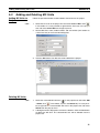
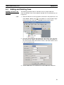
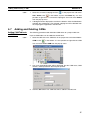
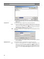
4-2
Adding and Deleting MC Units
Adding MC Units to
Projects
1,2,3...
Follow the procedure below to add a Motion Control Unit to the project.
1. Select the PLC icon in the project tree and select Insert - MC or click
in the toolbar. It is also possible to right-click the PLC icon in the project
tree and select Insert MC from the pop-up menu.
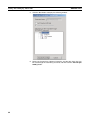
2. Set the MC Unit’s name, model number, and unit number (unit number as
a CPU Bus Unit) in the Insert MC Dialog Box.
3. Click the OK Button. The MC Unit will be added to the project.
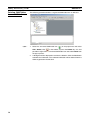
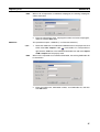
Deleting MC Units
1,2,3...
1. Select the unwanted MC Unit icon (
) in the project tree and select Edit
- Delete, click
in the toolbar, or press the Delete Key. It is also possible to right-click the unwanted MC Unit icon in the project tree and select
Delete from the pop-up menu.
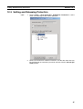
2. A dialog box will be displayed to confirm the deletion. Click the Yes Button
to delete the MC Unit. The selected MC Unit will be deleted from the
project tree.
31
Section 4-3
Adding and Deleting Tasks
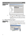
4-3
Adding and Deleting Tasks
Adding a Task to an
MC Unit
1,2,3...
The following procedure adds an individual task to a project’s MC Unit.
Up to 8 individual tasks can be added to one MC Unit. Each MC Unit must
have at least one task.
1. Select the MC Unit or Tasks Icon in the project tree and select Insert - Task
or click
in the toolbar. It is also possible to right-click the Tasks Icon
in the project tree and select Insert Task from the pop-up menu.
2. An individual task will be added to the MC Unit’s Tasks folder.
Deleting a Task from
an MC Unit
1,2,3...
The following procedure deletes a registered task from an MC Unit.
The lowest individual task will be deleted from the MC Unit’s registered tasks.
1. Select the Tasks Icon (
) in the project tree and select Edit - Delete, click
in the toolbar, or press the Delete Key. It is also possible to right-click
the Tasks Icon and select Delete from the pop-up menu.
2. A dialog box will be displayed to confirm the deletion. Click the Yes Button
to delete the task. The lowest individual task will be deleted from the MC
Unit’s registered tasks.
32
Section 4-4
Adding and Deleting Axes
4-4
Adding and Deleting Axes
Adding an Axis to an
MC Unit
1,2,3...
The following procedure adds an individual axis to a project’s MC Unit.
Up to 32 individual axes can be added to one MC Unit, of which 30 axes can
be physical.
1. Select the MC Unit, or the Parameter or Axes Icon in the project tree, and
select Insert - Axis or click
in the toolbar. It is also possible to right-
click the Axes Icon and select Insert Axis from the pop-up menu.
2. The Insert Axis Dialog Box will be displayed. Set the Axis’ name, axis number, physical axis number, and device type. Also set the Servo Driver series, Servo Driver model, Servo Driver version, and motor model if Servo
is set as the device type.
3. Click the OK Button. The individual axis will be added to the MC Unit.
33
Section 4-5
Adding and Deleting Programs
Deleting an Axis from
an MC Unit
1,2,3...
The following procedure deletes a registered axis from an MC Unit.
1. Select the unwanted axis icon (
lete, click
) in the project tree and select Edit - De-
in the toolbar, or press the Delete Key. It is also possible to
right-click the unwanted axis icon and select Delete from the pop-up menu.
2. A dialog box will be displayed to confirm the deletion. Click the Yes Button
to delete the axis. The selected axis will be deleted from the axes registered in the MC Unit.
4-5
Adding and Deleting Programs
Adding a Program to
an MC Unit
1,2,3...
The following procedure adds an individual program to a project’s MC Unit.
Individual programs can be added with program numbers from 0 to 499.
1. Select the MC Unit or the Motion Programs, or Program Icon in the project
tree and select Insert - Program or click
in the toolbar. It is also possible to right-click the Motion Programs or Programs Icon and select Insert
Program from the pop-up menu.
34
Section 4-6
Adding and Deleting Subprograms
2. The Insert Program Dialog Box will be displayed. Set the program name,
program number, comment, and axis declaration.
3. Click the OK Button. The individual program will be added to the MC Unit.
Deleting a Program
from an MC Unit
1,2,3...
The following procedure deletes a registered program from an MC Unit.
1. Select the unwanted program icon (
- Delete, click
) in the project tree and select Edit
in the toolbar, or press the Delete Key. It is also possi-
ble to right-click the unwanted program icon and select Delete from the
pop-up menu.
2. A dialog box will be displayed to confirm the deletion. Click the Yes Button
to delete the program. The selected program will be deleted from the programs registered in the MC Unit.
4-6
Adding and Deleting Subprograms
Adding a Subprogram
to an MC Unit
The following procedure adds an individual subprogram to a project’s MC
Unit.
Individual subprograms can be added with program numbers from 500 to 599.
35
Adding and Deleting Subprograms
1,2,3...
Section 4-6
1. Select the MC Unit or the Motion Programs or Sub Programs Icon in the
project tree and select Insert - Sub Program or click
in the toolbar. It
is also possible to right-click the Motion Programs or Sub Programs Icon
and select Insert Sub Program from the pop-up menu.
2. The Insert Sub Program Dialog Box will be displayed. Set the subprogram
name, subprogram number, comment, and axis declaration.
3. Click the OK Button. The individual subprogram will be added to the MC
Unit.
Deleting a
Subprogram from an
MC Unit
36
The following procedure deletes a registered subprogram from an MC Unit.
Section 4-7
Adding and Deleting CAMs
1,2,3...
1. Select the unwanted subprogram icon (
Edit - Delete, click
) in the project tree and select
in the toolbar, or press the Delete Key. It is also
possible to right-click the unwanted subprogram icon and select Delete
from the pop-up menu.
2. A dialog box will be displayed to confirm the deletion. Click the Yes Button
to delete the subprogram. The selected subprogram will be deleted from
the subprograms registered in the MC Unit.
4-7
Adding and Deleting CAMs
Adding CAM Tables to
an MC Unit
1,2,3...
The following procedure adds individual CAM tables to a project’s MC Unit.
Up to 32 CAM tables can be added to one MC Unit.
1. Select the MC Unit or the CAM Icon in the project tree and select Insert CAM or click
in the toolbar. It is also possible to right-click the CAM
Icon and select Insert CAM from the pop-up menu.
2. The Insert CAM Dialog Box will be displayed. Set the CAM name, CAM
number, and displacement decimal point position.
3. Click the OK Button. The CAM table will be added to the MC Unit.
37
Section 4-7
Adding and Deleting CAMs
Deleting CAM Tables
from an MC Unit
1,2,3...
The following procedure deletes a registered CAM table from an MC Unit.
1. Select the unwanted CAM table icon (
Edit - Delete, click
) in the project tree and select
in the toolbar, or press the Delete Key. It is also
possible to right-click the unwanted CAM table icon and select Delete from
the pop-up menu.
2. A dialog box will be displayed to confirm the deletion. Click the Yes Button
to delete the CAM table. The selected CAM table will be deleted from the
CAMs registered in the MC Unit.
38
SECTION 5
Editing Data
This section describes the operations used to edit data.
This manual shows how to edit data, but does not describe the functions of the data and parameters. For details on the
various data settings, refer to the MC Unit’s Operation Manual.
5-1
Editing Data . . . . . . . . . . . . . . . . . . . . . . . . . . . . . . . . . . . . . . . . . . . . . . . . . .
40
39
Section 5-1
Editing Data
5-1
Editing Data
This section describes how to edit data only. For details on the MC Unit’s setting contents, Unit parameters, and Servo Parameters, refer to the CS1WMCH71 Motion Control Unit Operation Manual (W419) or CJ1W-MCH71
Motion Control Unit Operation Manual (W435).
Overview of the
Editing Windows
The following table provides an overview of the editing windows.
Editing window
Symbol
Position Data
Unit Settings
Zone Settings
Tasks
Settings
Servo Settings
Motor Settings
Programs
Sub Programs
CAM Data
Editing Data
Overview
Names and comments can be set for system parameters and
variable addresses. Those names can be used to reference
parameters in the General Watch Window, programs, and
subprograms.
Position data can be edited. The names edited here can be
used to reference the data in the General Watch Window, programs and subprograms.
Unit parameters can be edited.
Zone parameters can be edited.
This function can be used in an MC Unit with the unit version
3.0 or later.
Motion task parameters can be edited.
All of the current motion task parameters are displayed in the
Edit Motion Task Parameters Window.
Axis parameters can be edited.
All of the current axis parameters are displayed in the Edit
Axis Parameters Window.
Parameters in the Servo Driver can be edited.
Motor parameters can be edited.
The motion task’s program can be edited.
The motion task’s subprograms can be edited.
Imported CAM table can be edited.
This section describes the main editing methods.
■ Direct Input
Input data directly.
The allowed setting range is displayed on the left side of the Status Bar, as
shown in the following diagram.
■ Drop-down List
Either click the ▼ button or press the Alt+i Keys. Click the desired setting
directly from the drop-down list to select it.
40
Section 5-1
Editing Data
■ Drop-down List (Check Boxes)
Either click the ▼ button or press the Alt+i Keys. Select the box to the left of
the desired setting to select that option.
Editing Symbols
■ Displaying the Window
With the project tree displayed, either double-click the desired MC Unit’s symbol or select the desired MC Unit’s symbol and press the Enter Key.
■ Switching between Edit Symbols Tabs
Either system parameters or variables can be edited by clicking the corresponding tab.
■ Editing in the System Parameters Tab
To edit the names of system parameters, click the System Parameters Tab
and either double-click the desired parameter or right-click the desired parameter and select Edit from the pop-up menu.
■ Editing in the Variables Tab
To edit the names of variables, click the Variables Tab and either double-click
the desired parameter or right-click the desired parameter and select Edit
from the pop-up menu.
A new variable can be added by right-clicking on the Variables Tab Page and
selecting Insert from the pop-up menu. Select or input the name, variable
type, data type, address, and comment in the displayed New Symbol Dialog
Box, and then press the OK Button.
Editing Position Data
■ Displaying the Window
With the project tree displayed, either double-click the desired MC Unit’s position data or select the desired MC Unit’s position data and press the Enter
Key.
Editing Unit Settings
■ Displaying the Window
With the project tree displayed, either double-click the desired MC Unit’s Unit
parameters or select the desired MC Unit’s Unit parameters and press the
Enter Key.
Editing Zone Settings
■ Displaying the Window
With the project tree displayed, either double-click the desired MC Unit's zone
parameters or select the desired MC Unit's zone parameters and press the
Enter Key.
41
Section 5-1
Editing Data
Editing Tasks
■ Displaying the Window
With the project tree displayed, either double-click the desired MC Unit’s task
or select the desired MC Unit’s task and press the Enter Key.
All of the current motion task parameters will be displayed in the Edit Motion
Task Parameters Window.
Editing Settings
■ Displaying the Window
With the project tree displayed, either double-click the desired MC Unit’s axis
parameters or select the desired MC Unit’s axis parameters and press the
Enter Key.
All of the current axis parameters are displayed in the Edit Axis Parameters
Window.
■ Switching between Edit Axis Parameters Tabs
The axis’ Allocation, Speed, Position, Origin, and Machine Parameters can be
edited by clicking the corresponding tab.
Editing Servo Settings
■ Displaying the Window
With the project tree displayed, either double-click the desired MC Unit’s servo
parameters or select the desired MC Unit’s servo parameters and press the
Enter Key.
Editing Motor Settings
■ Displaying the Window
With the project tree displayed, either double-click the desired MC Unit’s
motor parameters or select the desired MC Unit’s motor parameters and
press the Enter Key.
Editing Programs or Subprograms
■ Displaying the Window
With the project tree displayed, either double-click the desired MC Unit’s program/subprogram or select the desired MC Unit’s program/subprogram and
press the Enter Key.
■ Characteristics
• Instructions and comments are displayed in different colors.
• Symbol names in the symbols and position data names can be used
when writing programs. “$” is added to the front of names.
• Syntax checks can be performed in advance by compiling programs
offline.
Editing CAM Tables
■ Displaying the Window
With the project tree displayed, either double-click the desired MC Unit’s CAM
table or select the desired MC Unit’s CAM table and press the Enter Key.
42
SECTION 6
Saving and Reading Projects
This section describes the operations used to save and read new projects.
6-1
Saving a Project. . . . . . . . . . . . . . . . . . . . . . . . . . . . . . . . . . . . . . . . . . . . . . . .
44
6-2
Reading a Project . . . . . . . . . . . . . . . . . . . . . . . . . . . . . . . . . . . . . . . . . . . . . .
44
6-3
Importing Files . . . . . . . . . . . . . . . . . . . . . . . . . . . . . . . . . . . . . . . . . . . . . . . .
45
6-4
Exporting File . . . . . . . . . . . . . . . . . . . . . . . . . . . . . . . . . . . . . . . . . . . . . . . . .
48
43
Section 6-1
Saving a Project
6-1
Saving a Project
To save a project, select File - Save or File - Save As.
When editing a project that was saved before and saving it again with the
same name, select File - Save. The project will be overwritten. When saving a
new project or saving a project with a different name, select File - Save As.
Saving a Project by Name
1,2,3...
1. Select File - Save As. The following window will be displayed.
2. After entering the destination folder, file name, and file type, click the Save
Button. Use the default file type (*.mnh), since the project is being saved
as a CX-Motion-MCH project file.
6-2
Reading a Project
To read a project that has already been saved, select File - Open.
1,2,3...
1. Select File - Open.
2. From the Look in Drop-down List, select the drive and folder containing the
file.
3. Enter the project name, or select one from the file list. Set the file type to
*.mnh.
4. Click the Open Button.
44
Section 6-3
Importing Files
6-3
Importing Files
MC Miel for MCH Files
1,2,3...
This procedure imports a project file created as an MC Miel for MCH file (*.mil
filename extension).
1. Select the PLC icon in the project tree and either select File - Import or
click
in the toolbar. It is also possible to right-click the PLC icon and
select Import from Miel from the pop-up menu.
2. Enter the MC name, unit number, and Miel file name, then click the OK Button.
Symbol Files
This procedure imports a system parameter or variable file under the Symbol
Icon (*.csv filename extension).
1,2,3...
1. Select the Symbol Icon in the project tree and either select File - Import
or click
in the toolbar. It is also possible to right-click the Symbol Icon
and select Import from the pop-up menu.
2. Select the target system parameter or variable to be imported, enter or select the file name, and click the OK Button.
Position Data Files
This procedure imports a position data file (*.csv filename extension).
1,2,3...
1. Select the Position Data Icon in the project tree and either select File - Import or click
in the toolbar. It is also possible to right-click the Position
Data Icon and select Import from the pop-up menu.
45
Section 6-3
Importing Files
2. Enter the destination folder, file name, and file type, and then click the
Open Button.
Program Files
This procedure imports a program file (*.txt filename extension).
1,2,3...
1. Select the Programs Icon or an individual program icon in the project tree
and either select File - Import or click
in the toolbar. It is also possible
to right-click the Programs Icon or the individual program icon and select
Import Program or Import from the pop-up menu.
Note
When a file is imported to an individual program, the existing program will be
overwritten.
2. Enter the program name, program number, and select program, and then
click the OK Button.
Subprogram Files
This procedure imports a subprogram file (*.txt filename extension).
1,2,3...
1. Select the Sub Programs Icon or an individual subprogram icon in the
project tree and either select File - Import or click
in the toolbar. It is
also possible to right-click the Sub Programs Icon or the individual subprogram icon and select Import Sub Program or Import from the pop-up
menu.
46
Section 6-3
Importing Files
Note
When a file is imported to an individual subprogram, the existing subprogram
will be overwritten.
2. Enter the subprogram name, subprogram number and select subprogram,
and then click the OK Button.
CAM Files
This procedure imports a CAM file (*.csv filename extension).
1,2,3...
1. Select the CAM Icon or an individual CAM table icon in the project tree and
either select File - Import or click
in the toolbar. It is also possible to
right-click the CAM Icon or the individual CAM table icon and select Import
CAM or Import from the pop-up menu.
Note
When a file is imported to an individual CAM table, the existing CAM table will
be overwritten.
2. Enter the CAM name, CAM table number, and CAM table file, and then
click OK Button.
47
Section 6-4
Exporting File
6-4
Exporting File
Symbol File
This procedure exports a symbol file (*.csv filename extension) containing the
system parameters and variables.
1,2,3...
1. Select the Symbol Icon in the project tree and either select File - Export
or click
in the toolbar. It is also possible to right-click the Symbol Icon
and select Export from the pop-up menu.
2. Select the System Parameter and Symbol Variables Options, input the file
names (or click the Browse Button and select the file), and then click the
OK Button.
Position Data Files
This procedure exports a position data file (*.csv filename extension).
1,2,3...
1. Select the Position Data Icon in the project tree and either select File - Export or click
in the toolbar. It is also possible to right-click the Position
Data Icon and select Export from the pop-up menu.
2. Enter the destination folder, file name, and file type, and then click the Save
Button.
Program Files
This procedure exports a program file (*.txt filename extension).
1,2,3...
1. Select an individual program icon in the project tree and either select File
- Export or click
in the toolbar. It is also possible to right-click the in-
dividual program icon and select Export from the pop-up menu.
48
Section 6-4
Exporting File
2. Enter the destination folder, file name, and file type, and then click the Save
Button.
Subprogram Files
This procedure exports a subprogram file (*.txt filename extension).
1,2,3...
1. Select an individual subprogram icon in the project tree and either select
File - Export or click
in the toolbar. It is also possible to right-click the
individual subprogram icon and select Export from the pop-up menu.
2. Enter the destination folder, file name, and file type, and then click the Save
Button.
Multiple Program/
Subprogram Files
This procedure exports selected multiple program/subprogram files at the
same time (*.txt filename extension).
1,2,3...
1. Select the Motion programs, Programs, or Sub Programs Icon in the
project tree and either select File - Export or click
in the tool bar. It is
also possible to right-click one of the above icons and select Export from
the pop-up menu.
49
Section 6-4
Exporting File
2. Select the programs and subprograms to be exported, select the destination folder, and then click the Export Button.
CAM Data Files
This procedure exports a CAM data file (*.csv filename extension).
1,2,3...
1. Select an CAM table icon in the project tree and either select File - Export
or click
in the toolbar. It is also possible to right-click the CAM table
icon and select Export from the pop-up menu.
50
Exporting File
Section 6-4
2. Enter the destination folder, file name, and file type, and then click the Save
Button.
51
Exporting File
52
Section 6-4
SECTION 7
Transferring and Comparing Data
This section describes the operations used to transfer or compare data between the personal computer and Motion Control
Unit/Servo Driver, and to write data transferred to the Motion Control Unit to the Motion Control Unit's flash memory.
Note
Be sure that the personal computer is connected to the PLC via a connecting cable and that online
communications are established before transferring data, comparing data, or writing data to flash
memory.
7-1
Initial Settings for Online Connection . . . . . . . . . . . . . . . . . . . . . . . . . . . . . .
54
7-2
Setting/Changing Communications Specifications. . . . . . . . . . . . . . . . . . . . .
54
7-3
Transferring, Comparing, and Saving Data . . . . . . . . . . . . . . . . . . . . . . . . . .
56
53
Initial Settings for Online Connection
7-1
Section 7-1
Initial Settings for Online Connection
Initial Settings for the CPU Unit and MC Unit
1,2,3...
1. Set the MC Unit’s unit number (using the rotary switch on the front panel)
2. Set the DIP switch on the CPU Unit or the Controller Section of the NSJ
Controller.
a. For Communications via Toolbus:
• When using the peripheral port, set SW4 to OFF, or set SW4 to ON
and make appropriate setting of PLC Setup (set Programming Console Address 144 to 0400 Hex).
• When using the RS-232C port, set SW5 to ON, or set SW5 to OFF and
make appropriate setting of PLC Setup (set Programming Console Address 160 to 0400 Hex).
b.
For Communications via SYSMAC WAY (Host Link):
• When using the peripheral port, set SW4 to ON, or set SW4 to OFF
and make appropriate setting of PLC Setup. (Set Programming Console Address 144 to its default, 0000 Hex. If the default setting has not
been changed, leave the setting as it is.)
• When using the RS-232C port, set SW5 to OFF, or set SW5 to ON and
make appropriate setting of PLC Setup. (Set Programming Console
Address 160 to its default, 0000 Hex. If the default setting has not been
changed, leave the setting as it is.)
3. Create the I/O tables (using the CX-Programmer or a Programming Console).
7-2
Setting/Changing Communications Specifications
Communications Settings
1,2,3...
1. Right-click the PLC icon in the project tree and select Properties from the
pop-up menu. Select the Target PLC Setting on the PLC Properties Dialog
Box. The following dialog box will be displayed. Set the Device Type to be
connected to the PLC.
2. Set the Network Type.
Click the Network Type Drop-down List to display the list and select the desired communications method.
54
Section 7-2
Setting/Changing Communications Specifications
3. Make the network settings
To check or change the network settings, click the Settings Button in the
Network Type Area.
a. Make settings in the Network Tab Page.
b.
Connecting to the
PLC
Make settings in the Driver Tab Page.
Select Online - Work Online or click
in the toolbar. It is also possible to
right-click the PLC icon in the project tree and select Work Online from the
pop-up menu.
Note
When transferring driver parameters, the transfer may be stopped with the following message: “Error (36355) Communications to the device could not be
established or the connection has been broken. Check the communication
55
Transferring, Comparing, and Saving Data
Section 7-3
settings and connection method to the device.”
Open the PLC property to increase the response monitoring time in the PLC
Setup.
7-3
Transferring, Comparing, and Saving Data
Transferring to the MC Unit
1,2,3...
1. Select the MC Unit icon in the project tree and either select Online - Transfer - To MC or click
in the toolbar. It is also possible to right-click the
MC Unit icon in the project tree and select Transfer - To MC from the popup menu.
2. Select the data to be transferred and then click the OK Button.
56
Transferring, Comparing, and Saving Data
Section 7-3
3. If the Write to Flash Memory Option is selected, the transferred data will
be saved in flash memory. The transfer will start when the OK Button is
clicked. The progress of the transfer will be displayed, as shown in the following diagram.
Transferring from the MC Unit
1,2,3...
1. Select the MC Unit icon in the project tree and either select Online - Transfer - From MC or click
in the toolbar. It is also possible to right-click the
MC Unit icon in the project tree and select Transfer - From MC from the
pop-up menu.
57
Transferring, Comparing, and Saving Data
Section 7-3
2. Select the data to be transferred and click the OK Button. The progress of
the transfer will be displayed, as shown in the following diagram.
Comparing Data with the MC Unit
1,2,3...
1. Select the MC Unit icon in the project tree and either select Online - Transfer - Compare or click
in the toolbar. It is also possible to right-click the
MC Unit icon in the project tree and select Transfer - Compare from the
pop-up menu.
2. Select the data to be compared and then click OK Button.
58
Transferring, Comparing, and Saving Data
Section 7-3
3. When the transfer from the MC Unit is completed, the Compare MC Window will be displayed showing the comparison results.
4. Double-click Position Data, Programs, Sub Programs, or Cam data. The
following window will be displayed.
5. Click the Overview Button to display the Overview Window.
6. Select File - Save as to save the overview or detail view of the results of
comparing programs.
59
Section 7-3
Transferring, Comparing, and Saving Data
Writing Data to Flash
Memory
!Caution Always backup the data in the flash memory after downloading the program,
parameter data, position data, or CAM data to the MC Unit. Otherwise, the
original data (before the transfer) will be restored the next time that the power
is turned ON, which may cause unexpected operation.
1,2,3...
1. Select the MC Unit icon in the project tree and either select Online - Write
To Flash or click
in the toolbar. It is also possible to right-click the MC
Unit icon in the project tree and select Write To Flash from the pop-up
menu.
2. Select the data to be saved in the Data Type Options and click the Write
Button.
Note
If an error occurs while data is being written to the flash memory, the data may
not be written to the flash memory successfully. In this case, write the data to
the flash memory again after resetting the error.
Displaying Unit Information
1,2,3...
1. Select Online - Unit Information.
2. The MC Unit’s model and version information will be displayed.
60
Section 7-3
Transferring, Comparing, and Saving Data
Initializing Memory
1,2,3...
1. Select the MC Unit icon in the project tree and either select Online - Clear
Memory or click
in the toolbar. It is also possible to right-click the MC
Unit icon in the project tree and select Clear Memory from the pop-up
menu.
2. Select the data to be initialized and click the OK Button.
Batch Transfer (Computer to MC Unit)
1,2,3...
1. Select the PLC icon in the project tree and either select Online - Batch
Transfer - To All MC or click
in the toolbar. It is also possible to right-
click the PLC icon in the project tree and select Batch Transfer - To MC
from the pop-up menu.
2. Select the destination MC Unit in the Select MC Drop-down List. Select the
data to be transferred and click the OK Button.
Batch Transfer (MC Unit to Computer)
1,2,3...
1. Select the PLC icon in the project tree and either select Online - Batch
Transfer - From All MC or click
in the toolbar. It is also possible to
right-click the PLC icon in the project tree and select Batch Transfer From MC from the pop-up menu.
2. Select the source MC Unit in the Select MC Drop-down List. Select the
data to be transferred and click the OK Button.
61
Transferring, Comparing, and Saving Data
Section 7-3
Range Transfer (Computer to MC Unit)
1,2,3...
1. Right-click in the Edit Parameters Window or Edit Position Data Window
and select Range Transfer - To MC from the pop-up menu.
2. The data of the selected Value will be transferred to the MC Unit.
Range Transfer (MC Unit to Computer)
1,2,3...
1. Right-click in the Edit Parameters Window or Edit Position Data Window
and select Range Transfer - From MC from the pop-up menu.
2. The data of the selected Value will be transferred from the MC Unit.
62
SECTION 8
Monitoring
This section provides information on monitoring the MC Units. The error status, axis's present position, and variable values
are displayed in the Monitor Windows.
Note
Be sure that the computer and PLC are connected with the connection cable and the communications
between them are established before starting monitoring operations.
8-1
Status Monitor. . . . . . . . . . . . . . . . . . . . . . . . . . . . . . . . . . . . . . . . . . . . . . . . .
64
8-2
General Watch Window . . . . . . . . . . . . . . . . . . . . . . . . . . . . . . . . . . . . . . . . .
64
63
Section 8-1
Status Monitor
8-1
Status Monitor
Use the Status Monitor to monitor MC Unit errors, the present position of each
axis, and the program number in progress.
Starting the Status
Monitor
Click
in the toolbar.
If the CX-Motion-MCH is connected online, monitoring will start automatically;
if the CX-Motion-MCH is offline, monitoring will stop.
8-2
General Watch Window
The General Watch Window can be used to check and change variable values
(excluding system variables).
Starting the General
Watch Window
Click
in the toolbar.
If the CX-Motion-MCH is connected online, monitoring will start automatically;
if the CX-Motion-MCH is offline, monitoring will stop.
To check a variable, select Insert from the Context Menu and register the variable.
To change a variable’s value, change the value directly in the variable’s Value
column and press the Enter Key to confirm the change.
The variables registered in the General Watch Window can also be referenced again by saving the project.
64
SECTION 9
Operation
This section describes various operations on the axes of the MC Unit, including test run operations and program debugging.
Note
Operation from Support Tool is supported for MC Units with unit version 3.0 or later.
9-1
9-2
9-3
Switching to Monitor Mode . . . . . . . . . . . . . . . . . . . . . . . . . . . . . . . . . . . . . .
66
9-1-1
Starting Monitor Mode . . . . . . . . . . . . . . . . . . . . . . . . . . . . . . . . . . .
66
9-1-2
Ending Monitor Mode . . . . . . . . . . . . . . . . . . . . . . . . . . . . . . . . . . .
67
Test Run . . . . . . . . . . . . . . . . . . . . . . . . . . . . . . . . . . . . . . . . . . . . . . . . . . . . .
67
9-2-1
Executing a Test Run . . . . . . . . . . . . . . . . . . . . . . . . . . . . . . . . . . . .
67
9-2-2
Test Run Window . . . . . . . . . . . . . . . . . . . . . . . . . . . . . . . . . . . . . . .
68
Debugging the Program . . . . . . . . . . . . . . . . . . . . . . . . . . . . . . . . . . . . . . . . .
69
9-3-1
Setting Break Points . . . . . . . . . . . . . . . . . . . . . . . . . . . . . . . . . . . . .
69
9-3-2
Debugging the Program . . . . . . . . . . . . . . . . . . . . . . . . . . . . . . . . . .
70
65
Section 9-1
Switching to Monitor Mode
9-1
9-1-1
Switching to Monitor Mode
Starting Monitor Mode
1,2,3...
1. Select a PLC icon in the project tree and select Online - Work Online, or
right-click a PLC icon and select Work Online from the pop-up menu. It is
also possible to click
nected to the PLC.
in the toolbar. The CX-Motion-MCH will be con-
2. Select the MC Unit in the project tree, and then select Online - Monitor
Mode or click
in the toolbar. The following warning dialog box will be
displayed. Read the contents of the warning carefully. Click the OK Button
only after confirming safety.
3. The CX-Motion-MCH will switch to Monitor Mode, and the following Test
Run Window and Stop Axes Button will be displayed.
will be displayed
in the toolbar.
The Stop Axes Button can be used in Monitor Mode and will come to the
front of the displayed window. All axes will decelerate to a stop if the Stop
Axes Button is clicked.
66
Section 9-2
Test Run
Note
9-1-2
The Status Monitor Window will not be displayed in Monitor Mode. Also, the
MC Unit cannot be controlled from the ladder program in Monitor Mode.
Ending Monitor Mode
1,2,3...
1. Select Online - Monitor Mode or click
in the toolbar.
2. Monitor Mode will be ended, and the CX-Motion-MCH will display
the toolbar.
9-2
9-2-1
in
Test Run
Executing a Test Run
1,2,3...
1. Select the axis for which to execute a test run in the Test Run Window.
2. Click
to lock the selected axis.
3. To use an override, select the Axis Override Option and enter the override
set value. Click the Set Button to write the set value to the MC Unit.
4. Click the JOG, STEP, or Origin Buttons. The axis will be operated.
Note
(1) Clicking any of the operation buttons will operate the motor at the designated speed. Execute the operation only after confirming safety.
(2) The operation on the personal computer may not stop the motor. Provide
an emergency stop device externally to enable stopping the motor immediately at any time.
67
Section 9-2
Test Run
9-2-2
Test Run Window
Test Run
Axis No.
Position
Busy
Servo
Override
STEP
JOG
Origin Search
Origin Return
Forced Origin
Task Error
Axis Error
Unit Error
Clear All Errors
68
Lock Servo
Lock/Unlock
Multiple
Axis Override
Set
+
−
+
−
Sets the axis to operate.
Displays the current position of the axis.
Displays the operating status.
Locks/unlocks the axis.
Displays a dialog to lock/unlock multiple axes.
Sets the override value.
Range: 0.00 to 327.67%
Sets the override in the MC Unit.
Steps the axis in the positive direction.
Steps the axis in the negative direction.
Jogs the axis in the positive direction.
Jogs the axis in the negative direction.
Searches for the origin.
Returns the axis to the origin.
Force the current position to the origin.
Display the error code occurred in Task. Click
the Reset Button to reset the error.
Displays any error code for any error that has
occurred for the axis. Click the Reset Button to
reset the error.
Displays any error code for any error that has
occurred in the MC Unit. Click the Reset Button
to reset the error.
Resets all errors that have occurred in the task,
axis, and unit.
Section 9-3
Debugging the Program
Absolute Origin ABS Offset
Setting
Set
Teaching
Type
Address
Teach
Displays the value of the Absolute Origin Offset
set in the Axis Parameters of the MC Unit.
Sets the absolute origin.
Sets either a Feedback Present Position or
Command Present Position.
Sets the first address in which to store data
(position data number).
Range: 0 to 10239
Executes teaching.
After execution, the address will be incremented
automatically.
External I/O Status
9-3
Debugging the Program
The CX-Motion-MCH can be used to debug the motion program in an MC
Unit.
Before switching to Monitor Mode, click To MC or From MC to transfer the
motion program between the MC Unit and CX-Motion-MCH so that both the
MC Unit and CX-Motion-MCH have the same program.
Note
9-3-1
Debugging motion program is supported for MC Units with unit version 3.0 or
later.
Setting Break Points
1,2,3...
1. Display the program to debug.
2. Move the cursor to the step to set the break point, and click
point mark
3. Click
. A break
will be displayed.
again, the break point will be removed.
69
Section 9-3
Debugging the Program
9-3-2
Debugging the Program
1,2,3...
1. Display the program.
2. Servolock the axis to be used if the program operates the axis.
3. In the toolbar, select the number of the task to debug.
4. Click
in the toolbar, the MC Unit will execute the program. Program execution will stop at the first break point.
5. Set variables in the General Watch Window as required.
6. Click
in the toolbar to debug the program again from the first break
point. Click
Note
in the toolbar to debug the program one step at a time.
In the following case, program execution will not stop at a breakpoint and will
continue to the next break point.
• The first break point is skipped using the IF function.
When step 0004 is false, step 0007 would be executed next after step 0004. A
break point is set for step 0007, so program execution would stop at the step
that was executed immediately before step 0007. In this example, that would
be step 0004, i.e., program execution would stop immediately after executing
the IF statement in step 0004.
Program execution also may not stop at a break point set for the WHILE,
FOR, PARALLEL, and SWITCH control commands.
70
Debugging the Program
Note
Section 9-3
(1) Clicking any of the operation buttons will operate the motor at the designated speed. Execute the operation only after confirming safety.
(2) The operation on the personal computer may not stop the motor. Provide
an emergency stop device externally to enable stopping the motor immediately at any time.
71
Debugging the Program
72
Section 9-3
SECTION 10
Data Traces
This section describes the data trace function.
Note
Data traces are supported for MC Units with unit version 3.0 or later.
10-1 Data Traces . . . . . . . . . . . . . . . . . . . . . . . . . . . . . . . . . . . . . . . . . . . . . . . . . . .
74
10-1-1 Executing a Data Trace. . . . . . . . . . . . . . . . . . . . . . . . . . . . . . . . . . .
74
10-1-2 Changing the Graph Display . . . . . . . . . . . . . . . . . . . . . . . . . . . . . .
75
73
Section 10-1
Data Traces
10-1 Data Traces
10-1-1 Executing a Data Trace
1,2,3...
1. Select the PLC icon in the project tree and select Online - Work Online,
or right-click the PLC icon and select Work Online from the pop-up menu.
It is also possible to click
connected to the PLC.
in the toolbar. The CX-Motion-MCH will be
2. Select the MC Unit icon in the project tree, and then select Online - Data
Trace or click
in the toolbar. The Data Trace Window will be displayed.
3. Click
in the Data Trace Window. The Data Trace Configuration dialog
box will be displayed.
74
Section 10-1
Data Traces
4. Set the trigger conditions, trace objects, and number of samplings.
5. Click the Transfer [PC to MC] Button to write the set values to the MC Unit.
6. Click the OK Button to close the Data Trace Configuration Dialog Box.
7. Click
trace.
in the Data Trace Window. The MC Unit will execute the data
8. The trigger condition is activated, and the data trace is completed. The MC
Unit will transfer the results of the data trace to the CX-Motion-MCH automatically and display them graphically.
10-1-2 Changing the Graph Display
1,2,3...
1. Select
in the legend to display the required items.
2. Select
the data of the item to change.
3. Change the vertical scale using
dow.
4. Change the displayed position using
in the Graph Tools Win-
.
5. Select
to display the value at the cursor position.
6. Select
to display the difference between two points.
7. Click
in the Data Trace Window to save the data to a CSV file.
75
Data Traces
76
Section 10-1
SECTION 11
Backup and Restore
This section describes the operations used to back up data from MC Units and restore data to MC Units.
Note
• Be sure that the personal computer is connected to the PLC via a Connecting Cable and that online
communications are established before backing up and restoring data.
• Backing up and restoring data is supported for MC Units with unit version 3.1 or later.
11-1 Backup from MC . . . . . . . . . . . . . . . . . . . . . . . . . . . . . . . . . . . . . . . . . . . . . .
78
11-2 Restoring to MC . . . . . . . . . . . . . . . . . . . . . . . . . . . . . . . . . . . . . . . . . . . . . . .
78
11-3 Verifying Backup File with MC Unit . . . . . . . . . . . . . . . . . . . . . . . . . . . . . . .
79
77
Section 11-1
Backup from MC
11-1 Backup from MC
Use the following procedure to backup an MC Unit on the CX-Motion-MCH.
1,2,3...
1. Select Online - Backup and Restore - Backup from MC in online mode.
The following window will be displayed.
2. After entering or selecting the destination folder, file name and file type,
click the Save Button. Use the default file type (*.bkh), because the MC
Unit data is being saved in a CX-Motion-MCH backup file.
11-2 Restoring to MC
Use the following procedure to restore a backup file to an MC Unit.
1,2,3...
1. Select Online - Backup and Restore - Restore to MC in online mode.
The following message will be displayed.
2. Click the OK Button to display the following window.
78
Verifying Backup File with MC Unit
Section 11-3
3. Enter or select the folder to be looked in, the file name, and the file type,
and then click the Open Button. The following message will be displayed
after restoring backup data is done.
4. Click the Yes Button to start verifying.
11-3 Verifying Backup File with MC Unit
Use the following procedure to verify a backup file with an MC Unit.
1,2,3...
1. Select Online - Backup and Restore - Verify Backup file with MC Unit
in online mode. The following window will be displayed.
2. Enter or select the destination folder, file name, and file type, and then click
the Open Button. Verifying will start. A message will be displayed to tell if
the data is identical.
79
Verifying Backup File with MC Unit
80
Section 11-3
SECTION 12
Read Protection
This section describes the operations used to set and release protection on programs or cam data in MC Units, set and
change primary and secondary passwords, and switch the user.
Note
• Be sure that the personal computer is connected to the PLC via a Connecting Cable and that online
communications are established before setting or releasing read protection, setting or changing
passwords, or switching the user.
• Read protection is supported for MC Units with unit version 3.1 or later.
12-1 Read Protection . . . . . . . . . . . . . . . . . . . . . . . . . . . . . . . . . . . . . . . . . . . . . . . .
82
12-1-1 Read Protection. . . . . . . . . . . . . . . . . . . . . . . . . . . . . . . . . . . . . . . . .
82
12-1-2 User. . . . . . . . . . . . . . . . . . . . . . . . . . . . . . . . . . . . . . . . . . . . . . . . . .
82
12-1-3 Setting and Releasing Read Protection. . . . . . . . . . . . . . . . . . . . . . .
82
12-2 Setting and Changing Passwords . . . . . . . . . . . . . . . . . . . . . . . . . . . . . . . . . .
83
12-3 Setting and Releasing Protection . . . . . . . . . . . . . . . . . . . . . . . . . . . . . . . . . .
85
12-4 Switching the User . . . . . . . . . . . . . . . . . . . . . . . . . . . . . . . . . . . . . . . . . . . . .
86
81
Section 12-1
Read Protection
12-1 Read Protection
12-1-1 Read Protection
The CX-Motion-MCH can be used to protect all of programs and cam data in
an MC Unit from being read.
Note
Protection cannot be set for reading parameters. It also cannot be set for writing parameters, programs or cam data.
12-1-2 User
There are 3 types of user. Read protection can be set only by the primary
user. What data can be read depends on the user.
User
Primary user
Secondary user
Normal user
What can be done
Setting the primary password and the
secondary password
Setting and releasing protection
Specifying programs or cam data that
can be read through the secondary
password
Reading all programs and cam data
Reading only the programs and cam
data that can be read through the secondary password.
---
What cannot be done
---
Setting and releasing
protection
Reading all programs
or cam data for which
read protection is set.
Setting and releasing
read protection.
12-1-3 Setting and Releasing Read Protection
Only the primary user can protect data in an MC Unit by setting and releasing
protection on the data that can be read. To set protection, set a primary password and a secondary password and then select the data items that can be
read through the secondary password.
Read protection can be set or released using the primary password at any
time.
82
Section 12-2
Setting and Changing Passwords
12-2 Setting and Changing Passwords
1,2,3...
1. Select Online - Read Protection- Set/Change Password in online mode.
The following window will be displayed.
2. Enter the primary password and click the OK Button.
3. After entering the new password and the confirm password, click the
Transfer [PC to MC] Button.
Note
All programs and cam data cannot be read if the primary password
is forgotten. Please make a copy of the password and keep it in a
safe place.
4. A message to tell that the password has been set successfully will be displayed. When it appears, click the OK Button. The following window will be
displayed.
83
Setting and Changing Passwords
Section 12-2
5. Click the Yes Button to display the following window.
6. Select Set Protection or Release Protection, and the data items that can
be read through the secondary password, and then click the Transfer [PC
to MC] Button.
84
Setting and Releasing Protection
Section 12-3
12-3 Setting and Releasing Protection
1,2,3...
1. Select Online - Read Protection- Set/Release Protection in online
mode. The following window will be displayed.
2. Select Set Protection or Release Protection, and the data items that can
be read through the secondary password, and then click the Transfer [PC
to MC] Button.
85
Section 12-4
Switching the User
12-4 Switching the User
A current user can be switched to a different user. Switching to the primary or
secondary user requires the primary password or the secondary password.
1,2,3...
1. Select Online - Read Protection- Switch User in online mode. The following window will be displayed to request entering the primary password
in secondary/normal user status.
The following window will be displayed when the primary password is entered.
2. Select the user to be switched to. Enter the primary password to switch to
the primary user or the secondary password to switch to the secondary user, and then click the OK Button.
86
SECTION 13
Printing
This section describes the operations used to print project data.
13-1 Printing . . . . . . . . . . . . . . . . . . . . . . . . . . . . . . . . . . . . . . . . . . . . . . . . . . . . . .
88
87
Section 13-1
Printing
13-1 Printing
Printing Data and
Parameters
To print project data, select File - Print and select the desired data from the
following Print Choice Dialog Box.
The following data and parameters can be selected for printing.
Item
A
B
C
D
E
F
G
H
I
J
K
L
88
Name
Function
Project Tree
If this option is selected, the project tree is printed.
MC Unit
If this option is selected, the specified MC Unit parameters are printed.
All Data or Specified Data These options specify the range of MC Unit parameters to print.
All Data
Print all of the data.
Specified Data
Print only selected data and parameters.
Unit Parameter
Select this option to print the Unit Parameters
Zone Parameter
Select this option to print the zone parameters.
Task Parameter
All
Print all of the motion task parameters.
Individual
Print only the motion task parameters specified in the list.
Axis Parameter
All
Print all of the axis parameters.
Individual
Print only the axis parameters specified in the list.
Servo Drive
All
Print all of the servo parameters.
(Servo Parameters)
Individual
Print only the servo parameters specified in the list.
Motion Programs
All
Print all of the programs and subprograms.
(Includes subprograms.) Individual
Print only the programs and subprograms specified in the list.
CAM Data
All
Print all of the CAM table’s data.
Individual
Print only the CAM table’s data specified in the list.
Position Data
All
Print all of the position data.
Select Range
Print only the specified range of position data.
Print Address
Print only the address and value, not comment and name.
and Values only
Symbol
Print the symbols.
Section 13-1
Printing
Printing the Error Log
The Error Log can be printed.
To print the error log, display the Error Log Window and select File - Print
from the Error Log Window’s menu bar.
89
Printing
90
Section 13-1
SECTION 14
Error Log
This section provides information on the error log generated by the MC Unit.
14-1 Error Log. . . . . . . . . . . . . . . . . . . . . . . . . . . . . . . . . . . . . . . . . . . . . . . . . . . . .
92
14-2 Error Codes . . . . . . . . . . . . . . . . . . . . . . . . . . . . . . . . . . . . . . . . . . . . . . . . . . .
92
91
Section 14-1
Error Log
14-1 Error Log
Overview
The error log can record and display the up to 20 MC Unit errors. If more than
20 errors occur, the oldest error record will be deleted to make room for the
new error record.
Displaying the Error
Log
Select the MC Unit icon in the project tree and select Online - Error Log.
The Refresh Button can be clicked to read the latest error log information
from the MC Unit.
The Clear All Button can be clicked to delete the error log.
Note
Axis errors are not displayed in the error log.
14-2 Error Codes
■ Error Causes and Error Processing
For details on the probable causes of error codes and methods used to clear
errors, refer to Troubleshooting in the CS1W-MCH71 Motion Control Units
Operation Manual (W419) or CJ1W-MCH71 Motion Control Units Operation
Manual (W435), or click Help - Help Contents in the CX-Motion-MCH and
select Trouble Shooting - MC-UNIT, or refer to 15-1 Troubleshooting in this
manual.
92
SECTION 15
Troubleshooting
This section provides information on the troubleshooting methods for the MC Unit.
15-1 Troubleshooting . . . . . . . . . . . . . . . . . . . . . . . . . . . . . . . . . . . . . . . . . . . . . . .
94
15-2 Error Codes . . . . . . . . . . . . . . . . . . . . . . . . . . . . . . . . . . . . . . . . . . . . . . . . . . .
101
93
Section 15-1
Troubleshooting
15-1 Troubleshooting
Error Processing of
Online Errors
The following error message may be displayed when attempting to connect
online on the CX-Motion-MCH Basic Window. Use the following flow chart to
help identify and correct the error.
The "Failed to Connect to the PLC"
error message displayed.
Is the cable between the
computer and PLC
connected correctly?
No
• Check whether the cable is disconnected or broken.
• Check whether the communications settings are the
same for the computer's COM and CX-Server.
Yes
Is the connected PLC turned
ON?
No
Turn ON the PLC.
Yes
Was the I/O table created after the
MC Unit was mounted?
No
Create I/O table using the CX-Programmer or
Programming Console.
Yes
Is another Programming Device
that uses CX-Server (such as CXProgrammer) communicating
online?
No
Check whether PLC model (including CPU Unit model)
and the network type setting match among all the
Programming Devices that use CX-Server.
Yes
Check PLC Communications Settings
again.
• If a transfer operation fails when transferring servo parameters for many
axes, a timeout may have occurred. Increase the response monitoring
time in the PLC Setup.
94
Section 15-1
Troubleshooting
• A communications error may occur in the servo driver after the MC Unit is
restarted. If this occurs, restore the power supply to the Servo driver and
the MC Unit
Error Messages and
Remedies
The following table shows the probable causes and remedies of messages
that may be displayed during online operations.
Message
12289: No access right - Another tool is
occupying MCH. General or READ/
WRITE is not permitted
Probable cause
The CX-Motion MCH tried to get the
access right to the MC Unit but
another process (tool) has the access
right.
35355: Communications to the device
1. Communications between the
could not be established or the conneccomputer and the MC Unit have
tion has been broken. Check the commubeen disconnected, or the MC Unit
nication settings and connection method
power supply has been cut off.
to the device
2. Communications between the
computer and the servo drive timed
out.
32775: CX-Server has not been initialized The CX-Server is corrupted or might
by the application
not be installed.
Remedy
Wait until the other process releases
the access right. Or stop the other
process so that access will be
released.
1. Check the network setup and
check the power supply to the MC
Unit.
2. Increase the Response Timeout
Setting in the Network Settings of
the PLC.
Check whether the CX-Server is
installed and try restarting the application.
Either stop some of the applications
34845: CX-Server is currently processing The CX-Server is currently processing the maximum number of requests. or wait until processing for other applithe maximum number of requests. This
error indicates the application is thrashing The communications system is busy cations has been completed.
and cannot handle any more
the maximum possible communications
requests.
throughput of the device's connection
Wait until the other application is fin8720: Operation mode of MC Unit is
The operating mode is set to the
ished and then retry the operation.
wrong
wrong mode.
Or the mode was changed by another
application, like the CX-Programmer,
while CX-Motion MCH was writing or
saving data.
Check the data for validity before
4364: Invalid data. Failed to transfer
Parameter Read:
transfer.
• No. of words read is zero.
• Beginning read address is for an
odd-numbered byte. (For system
parameter and position data, the
byte address is not a multiple of 4.)
• No. of read words is an odd number
of bytes. (For system parameter and
position data, the byte size is not a
multiple of 4.)
Parameter Write:
• The beginning write address or number of write words does not have the
correct access unit for the area.
• Command sequence error.
Program Write:
• Number of data in the program information and the size of the program
transmitted do not match each other.
• There is no program information.
CAM Data Write:
• When writing the last frame, the
phase and displacement were not
written together.
• The number of data in the CAM
information and the size of the data
transmitted do not match each other.
95
Section 15-1
Troubleshooting
Message
514: No unit with the specified unit number address
Probable cause
User tried to transfer the data to an
MC Unit that is not connected to the
PLC.
515, 8196, 8452: The specified data not Program Read:
available in MC Unit
• The specified program does not
exist.
• An error has occurred in the program memory.
CAM Read:
• The specified CAM table does not
exist.
• An error has occurred in the CAM
data memory.
Servo Parameter Read:
• The specified data has not been
written.
Clear Program:
• The specified program does not
exist.
Clear CAM:
• The specified CAM data does not
exist.
8456: Cannot write the parameter
• The content of parameter data is
incorrect.
• An attempt was made to transfer a
parameter value that was too large.
10001: No Servo information found in MC An attempt was made to transfer the
servo parameters but there is no
Unit, cannot perform transfer from MC
servo information in the MC Unit.
Unit
Remedy
Check the hardware unit number and
correct it accordingly.
Make sure the data exist in MC Unit
Check the parameter values before
transfer.
Configure the MC Unit with the proper
servo parameter and motor parameter information before doing the transfer operation.
1. Check whether servo drive is con1: Servo Transfer - Servo parameter has This error occurs when:
nected.
been transferred successfully to MC Unit. • Servo drive is not connected
However servo parameters could not be
• Mismatch of axis numbers in project 2. Check whether the axis numbers in
transferred to Servo drive. Please check
servo drives and the project are
and the servo drives connected to
the servo drive connection.
same and correct them if they are
MC Unit.
different.
1: Save Servo Parameter - Servo param- • Series or models in the project and
eters saved in MC Unit. However failed to servo drive are different.
3. Check whether the servo drive
save in Servo drive
series or models are the same as
in servo drives and correct them if
they are different.
513: Remote network has not been
An attempt was made to read the data Connect the proper servo drive and
configure the drive with proper inforstarted (destination node not part of the
from a servo drive but servo drive is
mation, then try to read the data.
network). Communication with slave not not connected to MC Unit.
possible, or not allocated as servo axis
10002: Motor Parameter not set in hard- Servo parameters and motor parame- Write the parameters before reading
them.
ware, Hence fail to read
ter are not set in the servo and thus
cannot be read.
An attempt was made to read or write 1. Use the same PLC and MC series
10000: MC Model you have selected
does not match with unit connected.
data to or from an MC Unit from a difas those connected to computer.
ferent MC series.
2. Check the unit number.
66: A communication monitor time error
Communications with the PLC were
Switch other Support Software,
occurred.
disconnected for more than a certain including the CX-Programmer, to
period of time while the CX-Motionoffline status or increase the baud
MCH was in monitor mode.
rate, and then switch the CX-MotionMCH back to monitor mode.
96
Section 15-1
Troubleshooting
Message
4361: Parameter error/Inconsistent
Parameters error
8451: Cannot register nor write
Probable cause
• Servo parameters don’t exist in the
MC Unit.
• The specified parameter number
doesn’t exist in the Servo Driver.
Remedy
• Transfer Servo parameters to the
MC Unit.
• In the Axis Properties Dialog Box,
match the drive model and version
with the connected Driver.
1. The program capacity has been
1. Reduce the size of the program
exceeded.
and then transfer the program
again.
2. The CAM data capacity has been
exceeded.
2. Reduce the amount of CAM data
and then transfer the data again.
3. Writing to flash memory is not possible because a backup is being
3. Wait until the backup has been
performed.
completed, and then write to flash
memory.
97
Section 15-1
Troubleshooting
The following table provides a description and detailed description of the compilation errors that may be displayed while compiling programs.
1
2
3
4
Error code
Description
Too Many Blocks
No Description
No Description
Too Many Characters in one Block
5
Illegal Program Start
6
Illegal Program End
7
Illegal Motion Task Instruction
8
9
Reserved
Illegal Argument
10
Too Many Arguments
11
Too Many Parallel Branches
12
Illegal Branch/Parallel Structure
13
Illegal Axis Declaration
14
Position Specification Error
15
Speed Specification Error
16
Time Specification Error
98
Detailed description
Number of blocks of programming exceeded 800.
----Number of characters in one block exceeded 128 including
CR-LF.
Specification of operand 'P' value at a subprogram's PROG
command is greater than 1000 and lower than 499.
Specification of operand 'P' value at the main program's
PROG command is greater than 500 and below 0.
The END command was used outside of the main program.
The RETURN command was used outside of a subprogram.
No ENDIF for IF.
No NEXT for FOR.
No WEND for WHILE.
No SEND for SWITCH.
A command has been used that cannot be specified in a
motion task.
--Necessary operands have not been established to respond to
the command. Insufficient axis data to respond to the command.
The total number of operands exceeded 11.
The number of axes to respond to the command has
exceeded the number of programmable axes.
The total number of variables or immediate values has
exceeded the number of programmable axes.
An illegal operand was used.
The same operands were overlapped in one block.
Data for both axes and operand 'P' was set in the PARAM
command.
Value of operand 'N' (number of branches) in the PARALLEL
command has overflowed.
Number of branch blocks is smaller than N.
Number of branch blocks is larger than N.
Value of operand 'Q' (axis declaration) in the motion program
is zero.
The target position is outside of the usable range.
Examples:
MOVELINK command <Slave axis travel amount><Master
axis travel amount>
CAMBOX <Link distance>
CONNECT <Gear ratio denominator>
SYNCR <Travel amount at deceleration stop>
A speed-related operand (e.g., operands 'F', 'V') has exceeded
the limit.
Examples: Operand 'F' for MOVEL, MOVEC, and MOVETRV.
A speed-related operand (e.g., operands 'F', 'V') has exceeded
the limit.
Examples: Operand 'F' for MOVEL, MOVEC, and MOVETRV.
Troubleshooting
Error code
17
18
19
20
21
22
23
24
25
26
27
28
29
Section 15-1
Description
Number Specification Error
Detailed description
A number-related operand (e.g., operands 'C', 'E', and 'S') has
exceeded the limit.
Examples: @Operand 'C' for WORK, OFFPOS, Operand 'S' or
'E' for CAM, CAMBOX
Specification Error in Number of Times An operand related to number of times and data numbers
(operands 'L' or 'N') has exceeded the limit.
Example: @PARALLEL N <Number of branches>, SFTR,
SFTL N <Shift amount>
Mode Error
A mode-related operand (operand 'Q') has exceeded the limit.
Examples: Operand 'Q' for MOVELINK, CAMBOX.
Immediate Value Range Exceeded
An immediate value range (-2147483648 to 2147483647) or
digit number (10-digit) has overflowed.
Illegal Variable Data Type
A variable that cannot be used in commands or a substitutions
has been defined.
A data type that cannot be used in commands or substitutions
has been defined.
A variable ('S', 'C', an indirect specification, of OW0300 to
OW0AFF) that cannot be on the left side of a substitution has
been set.
A variable that cannot be written in the operand 'W' for FOR
has been set.
A variable that cannot be written has been set for the variable
to edit for XFER, CLEAR, SFTR, and SFTL.
The data type character of a variable was not B, W, L, or F.
Variable Address Range Exceeded
Neither hexadecimal operand parameters nor axis parameter
values have been set.
The hexadecimal digit number has exceeded eight digits.
The acronym followed by #, @ was not S, M, C, O, T, A, or I.
The hexadecimal digit number for a bit variable was not five
digits.
The hexadecimal digit number of variables other than bit variables was not four digits.
An odd-numbered address was set for the variable S, O, M, C,
or I.
The maximum value of the variable addresses has overflowed.
The individual data types of variables have exceeded the maximum value.
Illegal Expression
Multiple terms have been used in an operation command.
Illegal Nesting
The number of nesting levels of IF-ELSE-ENDIF exceeded the
limit.
The number of nesting levels of FOR-NEXT exceeded the
limit.
The number of nesting levels of WHILE-WEND exceeded the
limit.
Illegal Subprogram Specification num- Specification of operand 'P' value at the subprogram's SUB
ber
command is higher than 1000 or lower than 499.
Radius Specification, Multi-circumferThe operands 'R' and 'L' were specified simultaneously for the
ence Specification
MOVEC command
No Description
Sync Trailing Axis Specification Error
More than two of the same axis numbers have been set in one
block.
NSTOP/INC/ABL Duplication Error
Commands are overlapped as the result of repeating the
same command, such as NSTOP-NSTOP, INC-INC, ABL-ABL.
99
Troubleshooting
Error code
30
Description
Illegal Instruction
31
32
33
Instruction Duplication Error
';' missing
Illegal Argument
34
Immediate Value Error
35
Axis Name Error
36
37
Rotation Direction Error
NSTOP Mismatch Error
38
\\""Q\\"" argument of PROG is missing
39
IF-ELSE-ENDIF Error
40
41
42
43
WHILE-WEND Error
FOR-NEXT Error
LOOP-LEND Error
PARALLEL-JOINT-JWAIT Error
44
SWITCH-CASE-BREAK-SEND Error
45
Illegal Condition Expression
46
Substitution Expression Format Error
47
Program Header Block Number Overflow
100
Section 15-1
Detailed description
Another command has been set prior to the NSTOP/INC/ABL.
The INC/ABL command has been set prior to the NSTOP
command.
An unrecognizable command (command code) has been set.
The same commands were overlapped in one block.
There is no “;” in one block (within 128 characters).
Illegal characters for programs have been used.
Illegal operands have been used.
Illegal characters for axis parameters or operand parameters
have been used.
Something other than a variable or immediate value has been
set for an axis parameter or operand.
The first data in the INC or ABL was not operand data.
Immediate value with a decimal point has been used at a command for which decimal point setting is disabled.
Immediate value without a decimal point has been used for a
decimal-point settable command.
There was no “J” after the “[“.
After the “[J”, a character other than a numeric value has been
set or nothing has been set at all.
There was no “]”.
The axis number “x x” is more than 2 digits.
The axis number was not between 1 and 32.
MOVEC Q <Rotation direction> has exceeded the limit.
Other data for axes and operands has been set before the
NSTOP command.
No operand 'Q' existed at the Motion program's PROG command.
ENDIF and ELSE existed but no IF.
Only the ELSE has been set.
WHILE missing for WEND.
FOR missing for NEXT.
LOOP missing for LEND.
PARALLEL missing for JOINT and JWAIT.
Only JOINT has been set.
Only JWAIT has been set.
PARALLEL-JOINT-JWAIT has been set in the motion subprogram.
SWITCH missing for CASE, DEFAULT, BREAK, and SEND.
Another command has been set between SWITCH and the
first CASE.
DEFAULT order is incorrect.
At the command WHILE, STOPOP, IF, or WAIT, the format was
not conditional expression <Left side><Conditional expression> <Right side>
The substitution expression format is incorrect.
Unusable axis data or operand data for a substitution expression has been set.
Notation was incorrect, such as #MW0000+1=100;
The operator is a conditional expression.
Too many operators.
Number of program header blocks exceeded 800.
Section 15-2
Error Codes
Error code
48
49
Description
Program Header Block Number Mismatched
Program Header Program Number Mismatched
Detailed description
Number of program header blocks and number of actual
blocks do not match.
The program number of the program header and the program
number of the PROG command's operand 'P' do not watch.
15-2 Error Codes
For details on the probable causes of error codes and methods used to clear
errors, refer to Troubleshooting in the CS1W-MCH71 Motion Control Units
Operation Manual (W419) or CJ1W-MCH71 Motion Control Units Operation
Manual (W435), or click Help - Help Contents in the CX-Motion-MCH.
MC Unit Alarm Codes
Name
Main board code error
Error log
Error
Detail
code
code
0370h
0003h
Alarm
code
Cause and remedy
0003h
System code area error on the main board.
Main board RAM error
0004h
0004h
RAM error in the main board.
WDC error between the main
board and sub-board.
Internal HW-WDT error
Sub-board code error
User program error
CAM data error
PLC WDT error
0005h
0005h
0006h
0013h
0026h
0027h
0000h
0006h
0013h
0026h
0027h
0030h
WDC error was generated between the main board and
sub-board.
Internal HW-WDT error
System code area error on the sub-board.
User program area error.
CAM data area error
WDT error on CPU Unit occurred.
Follow the instructions in the applicable PLC manual.
CPU Unit did not execute end refresh processing within
cyclic service monitor time.
Check end refresh prohibition in CPU system setup. If prohibited, cancel it and turn the power OFF once, and then
ON again.
Increase CPU Unit cyclic service monitor time and turn the
power OFF once, then ON again.
Bus error occurred between CPU Unit and MC Unit.
CPU fatal error occurred.
Follow the instructions in the applicable PLC manual.
Follow the instructions in the applicable PLC manual.
0001h
PLC cyclic service monitor
error
0002h
Monitor 0031h
Time
[ms]
Bus error (PC21bus error)
CPU fatal error
000Eh
0015h
0000h
0000h
0032h
0033h
CPU non-fatal error
0016h
0000h
---
101
Section 15-2
Error Codes
Name
Error log
Error
Detail
code
code
Flash memory error
0370h
Alarm
code
0040h
0040h
Unit deceleration stop
0041h
0041h
CPU memory error
0044h
0044h
Cause and remedy
The following data could not be written in the Flash memory.
• Protect data
• ABS origin position data
• System parameters
• Servo parameters
• Position data
• User program
• CAM data
Try to save the data again. Replace MC Unit if this error
persists after retrying several times.
Deceleration stop input of MC Unit was turned ON.
After confirming the safety in the surrounding area, turn
OFF the bit [Deceleration Stop] and execute [Unit Alarm
Reset].
The following error occurred between CPU Unit and MC
Unit:
• This error occurs when custom data area or custom I/O
area of MC Unit is allocated to CPU’s EM area, and when
the specified EM areas are overlapping in executing the
file memory function of CPU Unit, or when restoring the
power after allocating custom data area or custom I/O
area to the EM area already specified with the file memory function.
• Release the file memory function of CPU Unit, correct the
allocation of the area used for the file memory function so
that it does not overlap with the area used for custom data
area or custom I/O area of MC Unit and reset the alarm,
or correct the allocation of the area used for custom data
area or custom I/O area so that it does not overlap with
the area used for the file memory function and restore the
power.
MC Unit Alarm Codes
Name
No Program
Sub-program nesting error
Variable address
error
Error log
Alarm
Cause and remedy
code
Error Detail
code
code
0372h 2001h 2001h The sub-program to be executed with GOSUB command does not exist.
Create and download an appropriate program with the Support Tool, or
0379h
check if the program No. specified by GOSUB is correct.
2002h 2002h There are six or more sub-program nesting levels. Check the applicable
program and correct the nesting to five levels or less.
2003h 2003h Attempted to access the addresses other than “PL0000 to PL27FF”
when specifying position data indirectly. Check the applicable program
and correct the position data area specified indirectly to PL0000 to
PL27FF.
Divide-by
–zero alarm
2004h 2004h Zero division has occurred in an operation command. Check if the calculation formula or the assigned values are correct.
Operation overflow
2005h 2005h Operation result cannot be stored. Check if the calculation formula or
the assigned values are correct.
2006h 2006h The program to be executed is corrupted. Download the applicable program with the Support Tool, save it to the F-ROM, and restore the power.
The followings can be the causes of the program destruction.
• Destruction of data in memory due to external noise
• The power of PLC (MC Unit) was turned OFF while writing to Flash
memory was in progress.
Program error
102
Section 15-2
Error Codes
Name
Axis reservation disable
Axis alarm generated
Position specification error
Error log
Alarm
Error Detail code
code
code
0372h
0379h
Cause and remedy
2007h 2007h The axis that was declared in a program could not be reserved.
• The operating mode is set to Manual Mode. Make sure the applicable
axis is not in use, and switch to Automatic Mode.
• The axis is used in another program. Wait until the program is completed, or stop the program to start another program.
• Axes to be used in subprogram are not reserved in the main program.
Reserve all the axes to be used in the subprogram with PROG in the
main program.
• The axis that has not been declared was selected. Check if the axes to
be used in the program are specified correctly. If the specification is
correct, declare the axes with PROG.
• In parallel execution, etc., a main program tried to use the axis already
declared by a subprogram. Correct the program to operate the axis
after the subprogram is completed.
• In parallel execution, etc., a subprogram tried to declare the axis
already being operated by a main program. Correct the program to call
the subprogram after the block currently using the axis is completed.
2008h 2008h An alarm has occurred in an axis controlled by a task. Remove the
cause of the axis alarm, and reset the alarm.
2009h 2009h The position specified with axis movement commands (except for CAM),
axis operation commands, SYNCR, MOVEMODI, OFFPOS, and LATCH
exceeded the allowable position range. Since the range of pulse unit
system is expressed in 32-bit, the allowable range has to satisfy the following formula:
−Command unit limit ≤Command unit system position ≤ +Command unit
limit
Command unit limit [on machine] ≥
2147483647 [on motor] ×
P5AA04 [Command unit/1 machine
rotation] × P5AA06 [on machine]
9001h [No. of encoder pulses/1 motor
rotation] × P5AA05 [on motor]
Correct the applicable position to satisfy the formula above. When specifying with real numbers, check the setting value of the axis parameter
[P5AA02: Position command decimal point position].
• With Traverse (MOVETRAV command):
This error occurs when the operand “Winding axis rotations” = 0. Correct the program so that “Winding axis rotations” is not 0.
103
Error Codes
Name
Speed specification
error
Time specification
error
Number specification error
Count specification
error
104
Section 15-2
Error log
Alarm
Cause and remedy
Error Detail code
code
code
0372h 200Ah 200Ah The following operands have exceeded the allowable range:
• F (MOVEL, MOVEC, MOVETRAV), V (MOVEI, MOVET), SPEED com0379h
mand.
Correct the applicable operands. When specifying with real numbers,
check the setting value of the task parameter [P00M10: Interpolation
feed decimal point position].
200Bh 200Bh The following operands have exceeded the allowable range:
• T (MOVET, CAM, SPEED, TORQUE, SPEEDR, TORQUER, DWELL)
Correct the applicable operands.
• With Time-specified Positioning (MOVET command):
[Speed of each axis] = Travel distance of each axis/Positioning time
This error occurs when the speed specified by the above formula
exceeds the axis–speed parameter [P2AA01: Maximum rapid feed rate].
Check if the setting of the parameter is correct, and if so, correct the program.
200Ch 200Ch The following operands have exceeded the limit:
• C (WORK, OFFPOS), E, S (CAM, CAMBOX, FOR)
Correct the applicable operands.
• With CAM, CAMBOX:
This error occurs when setting the operands as [Starting data number]
= [Ending data number], or when setting the operands as [Starting data
number] ≥ [Ending data number] in using global general variables or
position data for cam data.
• When using cam table for cam data, correct the program as [Starting
data number] ≠ [Ending data number]. When using global general variables or position data, correct the program as [Starting data number] <
[Ending data number].
200Dh 200Dh The following operands have exceeded the range:
• L (MOVEC, MOVETRAV, FOR), N (PARALLEL, SFTR, SFTL, XFER,
CLEAR)
Correct the applicable operands.
• With PARALLEL:
This error occurs when setting the value exceeding the Max. No. of
branches for the unit (the value set in the system parameter [P00002:
No. of parallel branches]). Either correct (increase) the system parameter [P00002: No. of parallel branches], or correct (decrease) the No. of
branches of the PARALLEL command for the motion program.
Section 15-2
Error Codes
Name
Mode specification
error
Other operand error
--Circular interpolation travel distance
over
Circular interpolation radius error
Error log
Alarm
Cause and remedy
Error Detail code
code
code
0372h 200Eh 200Eh The following operand has exceeded the range.
• Q (MOVEC, MOVETRAV, MOVELINK, CAMBOX)
0379h
Correct the applicable operands.
200Fh 200Fh The following operands have exceeded the range.
• K (CAM, CAMBOX)
• B (MOVELINK, CAMBOX, CONNECT, SYNC, ADDAX)
• TORQUE
• SIN, COS, ASIN, ACOS, SQT, LGN, BIN, BCD
Correct the applicable operands.
2010h 2010h --2011h 2011h Travel distance specified in MOVEC is too great.
• The tangent arc length has exceeded 2147483647. Check the program
and correct the setting value so that it will not exceed the allowable
range. (When specifying with variables, check if the substitution formula is correct.)
• The radius has exceeded 2147483647. Check the program and correct
the setting value so that it will not exceed the allowable range. (When
specifying with variables, check if the substitution formula is correct.)
2012h 2012h The following instructions have been given in MOVEC.
In Radius specification: The radius is specified to 0.
• Check the program and correct the radius to the value larger than 0.
(When specifying with variables, check if the substitution formula is correct.)
• In Center specification: The start or end point, and the center are at the
same position.
Check the program and correct it so that the start or end position are not
on the center.
105
Section 15-2
Error Codes
Name
Control mode error
--Same axis specification multiplicity
--Synchronous slave
axis specification
error
106
Error log
Alarm
Error Detail code
code
code
0372h
0379h
Cause and remedy
2014h 2014h • A position control command (MOVE, etc.) or speed control command
(SPEED) was executed during Torque control (TORQUE). Correct the
program so that position control commands or speed control command
will not be executed during TORQUE execution.
• SPEED or TORQUE was executed during position control command
execution. Correct the program so that SPEED or TORQUE will not be
executed during position control command execution.
• Position control commands other than MOVE was executed during
SPEED command execution. Correct the program so that any position
control command other than MOVE will not be executed during SPEED
command execution.
2015h 2015h --2016h 2016h • Multiple commands were executed on the same one axis using parallel
branches. (Or when a main program is trying to use the axis being
used by the subprogram called by the main program, etc.) Correct the
program so that multiple commands are not executed on one axis from
multiple rows in the program.
• Axis movement command was executed on the axis, which is in synchronous execution as a slave axis. Correct the program so that any
axis movement command will not be executed during synchronization.
• The axis, which was specified as a slave axis has been a slave axis of
the different type of synchronous command. Correct the program so
that any slave axis is not shared between commands.
• When a command requiring a latch input was executed, and the latch
range parameter is being written, another latch-requiring command
was executed on the same axis. Correct the program so that any latchrequiring command will not be executed on the same axis, or the timings do not overlap.
2017h 2017h --2018h 2018h The axis that is specified as a slave axis has already been used as the
master axis. When an axis is to be operated as a slave axis of an axis
and the slave axis is to be used as a master axis of another axis, the
program (to change the order of specification) has to be arranged so
that the axis is specified as a slave axis of an axis first, and then as a
master of another axis.
Section 15-2
Error Codes
Name
Parameter setting
error
Axis declaration error
Error log
Alarm
Error Detail code
code
code
0372h
0379h
Cause and remedy
2019h 2019h <PARAM>
System parameters:
• Attempted to change a parameter that cannot be changed after restoring the power.
• Attempted incorrect parameter setting.
Check the program so that correct values can be set. (When specifying
with variables, check if the substitution formula is correct.)
Servo parameters:
• Attempted to change a parameter that cannot be changed after restoring the power.
• Attempted to set incorrect setting value
• Attempted to set incorrect number.
• Attempted to change parameter of other tasks or undeclared axes.
Check and correct the program so that correct values can be set.
(When specifying with variables, check if the substitution formula is correct.)
• Attempted to set servo parameters on virtual axes or I/O axes.
Servo parameters cannot be set on virtual axes and I/O axes. Correct
the program.
<LATCH>
• The contents of [900Ah: Positive latch enabled range] and [900Bh:
Negative latch enabled range] in the motor parameters are not written
correctly.
After checking the applicable axis and if the motor model is correct,
transfer the motor parameters and save them to F-ROM (when individual, specify servo parameter), and restore the power.
<SPEED>
• The contents of [900Dh: Position loop gain] and [900Eh: Position loop
gain index] in the motor parameter are not written correctly.
After checking the applicable axis and if the motor model is correct,
transfer the motor parameters and save them to F-ROM (when individual, specify servo parameter), and restore the power.
201Ah 201Ah Axis other than servo/virtual axis is included in the axis declaration.
Check the parameter [P1AA02: MECHATROLINK-II device classification] of the applicable axis. If the setting of the parameter is correct, correct the program.
107
Error Codes
Section 15-2
Axis Alarm Codes
Name
Error log
Alarm
Cause and remedy
code
Error Detail
code
code
--037Ah 3001h 3001h --Over travel, positive direc- 3002h 3002h • The over travel signal in positive direction has turned ON during
0399h
tion
axis movement.
• After resetting the alarm, attempted to operate the axis in the
positive direction with the positive direction over travel signal ON.
Move the axis in the negative direction manually.
Over travel, negative
3003h 3003h • The over travel signal in negative direction has turned ON during
direction
axis movement.
• After resetting the alarm, attempted to operate the axis in the
negative direction with the negative direction over travel signal
ON.
Move the axis in the positive direction manually.
Over travel, both direc3004h 3004h • The over travel signals in both directions have turned ON during
tions
axis movement or when the axis was about to move.
• After resetting the alarm, attempted to operate the axis with the
over travel signals in both directions ON.
Check if the over travel signals for both directions are wired correctly.
Software limit, positive
3005h 3005h • The axis entered the software limit area in positive direction durdirection
ing axis movement with the origin defined. Check if the setting
value of the axis parameter [P3AA02: Positive direction software
limit] is correct. (The error may occur when executing circular
interpolation right on the software limit values.) If the setting
value is incorrect, set a larger limit value. When the value is correct, correct the program or travel distance of the axis.
108
Section 15-2
Error Codes
Name
Error log
Error Detail
code
code
Alarm
code
Cause and remedy
3006h
3006h
Servo OFF
3007h
3007h
Synchronous communications alarm
300Ah
300Ah
Communications alarm
300Bh
300Bh
• The axis entered the software limit area in negative direction during axis movement with the origin defined. Check if the setting
value of the axis parameter [P3AA02: Negative direction software
limit] is correct. (The error may occur when executing circular
interpolation right on the software limit values.) If the setting
value is incorrect, set a larger limit value. When the value is correct, correct the program or travel distance of the axis.
• The axis that received a movement command is in Servo OFF
state. (In operations with programs, this alarm will occur when
the applicable axis is specified at the beginning of the block and
a movement command is executed for the axis that is in Servo
OFF state.) Switch the axis to Servo lock state.
• Servo OFF was executed for the axis receiving a movement command.
Do not execute Servo Unlock during axis movement.
An error was occurred in the MECHATROLINK synchronous communications. The followings are the possible causes:
• Disconnection, breakage of MECHATROLINK cable
Check the MECHATROLINK cable.
• Communications error caused by noise
Remove the cause of the noise.
When this error persists even after providing these remedies, the
Driver (NS115) or MC Unit may be broken. Replace the broken
one with a new unit.
Detected MECHATROLINK communications errors twice in a row.
Or the No. of error detections specified in [P1AA06: MECHATROLINK-II communications error detection setting] has been
exceeded. The followings are the possible causes:
• Disconnection, breakage of MECHATROLINK cable
Check the MECHATROLINK cable.
• Communications error caused by noise
Remove the cause of the noise.
When this error persists even after providing these remedies, the
Driver (NS115) or MC Unit may be broken. Replace the broken
one with a new unit.
Software limit negative
direction
037Ah
0399h
109
Section 15-2
Error Codes
Name
Command timeout
Absolute encoder error
Error log
Error Detail
code
code
037Ah
0399h
Alarm
code
Cause and remedy
300Ch 300Ch A MECHATROLINK command could not be completed within a
fixed period of time (10 seconds). The followings are the possible
causes:
• Disconnection, breakage of MECHATROLINK cable
Check the MECHATROLINK cable.
• Communications error caused by noise
Remove the cause of the noise.
When this error persists even after providing these remedies, the
Driver (NS115) or MC Unit may be broken. Replace the broken
one with a new unit.
300Dh 300Dh Data from the ABS encoder could not be processed normally.
• Initial multi-turn value exceeds the multi-turn limit.
Set the same value in the driver parameter [Pn205: Multi-turn
limit setting] and the motor parameter [900C: Multi-turn limit].
After the setting is completed, restore the power, reset the alarm,
and perform the origin setting.
• After origin setting, the following values related to B/A were
changed.
Note B = No. of encoder pulses × P5AA05
A = P5AA04 × P5AA06
B/A is integer calculation and the result is to be reduced.
After the change was made (saving to F-ROM), restore the
power, reset the alarm, and perform origin setting.
• The multi-turn limit value in the driver parameter or the motor
parameter was changed after origin setting.
After the change was made (saving to F-ROM), restore the
power, reset the alarm, and perform origin setting. (When the
multi-turn value of the driver parameter was changed, make sure
to perform “Absolute encoder multi-turn amount setting change”
on the driver.)
• Servo driver is set as an incremental encoder. Set the driver
parameter Pn002 digit No. 2 to “0” (used as an absolute encoder)
and restore the power.
• Disconnection, breakage of encoder cable
Check the encoder cable.
• Communications error caused by noise
Remove the cause of the noise.
When this error persists even after providing these remedies, the
encoder or MC Unit may be broken. Replace the broken one with
a new unit.
110
Section 15-2
Error Codes
Name
Error log
Error Detail
code
code
Alarm
code
Cause and remedy
300Eh
300Eh
Origin proximity reverse
alarm
300Fh
300Fh
Over travel reverse alarm
3010h
3010h
Synchronous slave axis
speed over
3011h
3011h
Excessive error alarm
3012h
3012h
MECHATROLINK-II slave
axis error 1
3013h
3013h
The limit switch in the direction of the search was already ON
when a one direction-mode origin search was executed.
Check the status of the limit switch in the origin search start direction. Also check and correct the origin search start position.
The limit reversal mode origin search cannot be performed
because the limit switch in the direction of the search turned ON
while the search was reversing.
Check the status of the limit switch in the origin search start direction. And check and correct the positions of the origin proximity
limit switch and the limit switch.
The limit reversal mode origin search cannot be performed
because the limit switch or deceleration LS in the opposite direction of the search turned ON while the search was reversing due
to over travel signal ON in the direction of the origin search.
Check the status of the limit switch in the origin search start direction. And check and correct the positions of the origin proximity
limit switch and the limit switch.
With synchronous commands (MOVELINK, CAMBOX, CONNECT, SYNC, ADDAX), the speed of the slave axis exceeded the
speed specified in [P2AA01: Maximum rapid feed rate].
Check if the setting value in the parameter is correct. If it is correct,
correct the program. With CAMBOX, check also the displacement
of the CAM data.
Position error exceeded the setting value of the axis parameter
[P3AA06: Position error alarm detection value].
Check if the set value is appropriate for the system configuration
and correct it as needed.
When the value is correct, check the followings:
• Breakage of encoder cable
• Malfunction caused by noise
• Unadjusted servo system
• Unadjusted or unprepared machine system
These causes are to be removed.
An error occurred on a MECHATROLINK-II slave axis.
Check the MECHATROLINK slave of the applicable node No. and
remove the cause of the error. Slave alarm codes are stored in the
error log in the MC Unit.
Over travel already ON
037Ah
0399h
111
Section 15-2
Error Codes
Name
Error log
Error Detail
code
code
Alarm
code
Cause and remedy
3015h
3015h
No origin proximity signal
3016h
3016h
Origin proximity and over
travel simultaneously ON
3017h
3017h
Attempted to execute a command that cannot be executed as an
axis. (The command that requires an external signal (MOVEI, etc.)
was executed on the virtual axis, or the winding axis of
MOVETRAV is not set as an unlimited length axis, etc.)
Correct the applicable parameters or program.
During an origin search in the limit reversal mode, there was no
deceleration limit switch in between over travel of both directions.
Provide the origin proximity limit switch, or check if the limit
switches themselves or wiring is normal.
During an origin search, the deceleration limit switch and the over
travel in direction of the search were turned ON simultaneously.
Check if the origin proximity signal, or over travel signals for both
directions are wired correctly.
No origin signal
3018h
3018h
3019h
3019h
Counter latch resource
violation
301Ah
301Ah
Gear ratio range error
3040h
3040h
Axis classification error
Excessive speed command
037Ah
0399h
037Ah
0399h
During an origin search, the over travel signal turned ON while
waiting for the origin signal (while waiting for the rise of phase-Z
after the fall (ON to OFF) of the origin proximity limit switch).
Check if the settings of the axis parameter [P4AA06: Origin determine signal] and the servo parameter [Pn511: Input signal select
5] are correct (if the applicable signal is enabled).
If the settings are correct, check the followings:
• Problem on Phase-Z of the encoder
• Breakage of encoder cable
• Too small distance between the origin proximity limit switch and
the limit switch
These causes are to be removed.
The axis speed has exceeded maximum rapid feed rate during the
following command execution:
• MOVEL (Axes except for the one with the longest travel distance)
• MOVEC (Linear axis: if not specified with the tangential speed of
the circular interpolation portion.)
• MOVETRAV (Traverse axis)
• CAM
Check if the speed set in [P2AA01: Maximum rapid feed rate] is
correct. If it is not correct, set a higher speed. If it is correct, lower
the feed rate of the program or lower the speed using override.
With DATUM, MOVEI, MOVELINK, CAMBOX, SYNC, and LATCH
commands, attempted to execute the functions simultaneously
that require the counter latch.
Check the axis specified for the Latch and correct the program so
that there are no redundant specifications (executing LATCH command on the axis already executing LATCH command, executing
LATCH command on the axis waiting for the synchronization start
conditions to be satisfied, or etc.).
Relations between the No. of encoder pulses and command unit is
not normal. When the following expression is not satisfied, the
error will occur:
1/7FFFFFFFh ≤ B/A ≤ 7FFFFFFFh
Note B = No. of encoder pulses × P5AA05
A = P5AA04 × P5AA06
B/A is integer calculation and the result is to be reduced.
Set the parameters so that the formula above is satisfied.
112
Error Codes
Section 15-2
MLK Device Alarm Codes
Name
Depending on the device
Error log
Cause and remedy
Error code
Detail code
037Ah
4000h
Depending on the device.
to
+
Follow the directions of the applicable manuals.
0399h
Alarm code of
each device
113
Error Codes
114
Section 15-2
Revision History
A manual revision code appears as a suffix to the catalog number on the front cover of the manual.
Cat. No. W448-E1-05
Revision code
The following table outlines the changes made to the manual during each revision. Page numbers refer to the
previous version.
Revision code
01
02
03
Date
Revised content
November 2005 Original production
July 2006
The following changes and corrections were made in updating from software version
1.0 to version 2.0.
Page xvi: Caution added.
Page 4: Test run and program debugging functions added to online operations and
data trace function added.
Page 6: Version upgrade information added.
Pages 12 and 13: Procedures altered.
Page 13: Program and Debug commands added.
Page 15: Debug Watch Window and Test Run commands added.
Page 16: Monitor Mode command added to Online operations and Program and
Debug menus added.
Pages 17 to 19: Toolbars updated for new functionality.
Page 22: Debugging, text run, and data trace items added.
Pages 34 and 35: Zone settings added.
Page 47: Note added.
Pages 48 to 50: Screen shots replaced.
Page 57: New sections 9 and 10 added.
Page 58: Screen shot replaced and zone settings added.
June 2007
Cover: Model numbers added and “SYSMAC” removed.
Page ix: Middle row of table removed and “CS1W” added to bottom row (two locations).
Pages ix and 2: Windows XP and Vista added.
Pages ix and 2: CX-One version changed to 2.1.
Page xiii: Version information moved from page 6 and new version information
added.
Page 2: “CP-series PLCs” added to top table.
Page 4: Functions added to table after “Data Trace.”
Page 6: Information moved to page xiii.
Page 8: Heading added.
Page 9: Section added.
Pages 15 and 18: Row added for “Find in Programs.”
Pages 17 and 24: Rows added for “Backup and Restore” and “Read Protection.”
Page 18: Toolbar illustration replaced.
Page 26: Bottom screen capture replaced.
Page 27, 50, and 52: Top screen capture replaced.
Page 46: Section added.
Page 51: Middle screen capture replaced.
Page 52: New step 2 and steps 4 to 6 added.
Page 71: New sections 11 and 12 added.
115
Revision History
Revision code
04
05
116
Date
June 2008
Revised content
Page xi: Changed applicable OS’s.
Page xvi: Added version upgrade information.
Page 2: Added "CJ2 CPU Units," corrected model numbers, and corrected software
version.
Page 10: Added new section (2-2-3).
December 2009 Made revisions for the upgrade to version 2.24 (including revisions accompanying
the upgrade from CX-One version 3.2 to 4.03 and for support for Windows 7).
OMRON Corporation
Industrial Automation Company
Authorized Distributor:
Tokyo, JAPAN
Contact: www.ia.omron.com
Regional Headquarters
OMRON EUROPE B.V.
Wegalaan 67-69-2132 JD Hoofddorp
The Netherlands
Tel: (31)2356-81-300/Fax: (31)2356-81-388
OMRON ELECTRONICS LLC
One Commerce Drive Schaumburg,
IL 60173-5302 U.S.A.
Tel: (1) 847-843-7900/Fax: (1) 847-843-7787
OMRON ASIA PACIFIC PTE. LTD.
No. 438A Alexandra Road # 05-05/08 (Lobby 2),
Alexandra Technopark,
Singapore 119967
Tel: (65) 6835-3011/Fax: (65) 6835-2711
OMRON (CHINA) CO., LTD.
Room 2211, Bank of China Tower,
200 Yin Cheng Zhong Road,
PuDong New Area, Shanghai, 200120, China
Tel: (86) 21-5037-2222/Fax: (86) 21-5037-2200
© OMRON Corporation 2005 All Rights Reserved.
In the interest of product improvement,
specifications are subject to change without notice.
Printed in Japan
Cat. No. W448-E1-05
1209