1
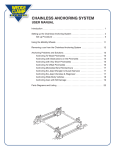
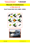
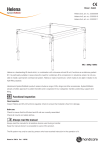
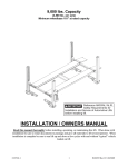
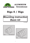
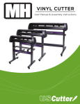
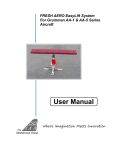
FULL FRAME ANCHORING SYSTEM
USER MANUAL
February 2006
Full Frame Anchoring System – User Manual
CONTENT
Introduction
1
Setting up the Full Frame Anchoring System
4
Anchoring procedures using the:
- Box Frame and C Section Adapter
- Leaf Spring Adapter
- Torsion Bar Adapter
- Frame Hole Adapter
6
Removing Vehicle from the Full Frame Anchoring System
10
Parts Diagram and Listing
11
Figure 1: FFAS with Mounted Frame
1
Full Frame Anchoring System – User Manual
INTRODUCTION
This manual explains how to mount a Truck or SUV on the Wedge Clamp Full Frame Anchor
System (FFAS). The FFAS is designed to let you anchor a Full Frame Vehicle as an
independent floor system, or to a Wedge Clamp Chainless floor anchoring system; allowing you
to make multiple pulls without changing the anchoring attachments and without damaging the
vehicle in the pulling process.
An important component of the Wedge Clamp FFAS is the patented Universal 2-Axis Swivel
Base Assembly (Figure 2). This clamping system is designed to anchor the full frame vehicle
regardless of the type of frame (Box or C-Section) and, or, the curvature of the frame rail itself.
The Leaf Spring, Torsion Bar and Jig Hole adapters provide the versatility of the type of clamp
procedure needed for different vehicles.
Figure 2: Close-Up of
Swivel Base Assembly
WARNING: Serious damage or injury can occur if a vehicle is not anchored
securely for pulling. It is your responsibility to evaluate the vehicle and to
determine the safest anchoring method. Always check the anchoring points
during pulling to be sure that the vehicle remains securely anchored.
2
Full Frame Anchoring System – User Manual
The Full Frame Anchoring System consists of the following components:
Quantity
2
4
2
12
4
8
8
2
Description
Anchoring Crossbeams
Swivel Clamp Assembly
Anchoring side bar - 6’ (1.83 m)
Steel wedge
Chainless R7 anchoring stand
Rail lock
Rail spacer wedge
Anchoring rail, beveled & slotted
Part #
92860
92880
17102
20060
17603
17604
17605
17900
92880
92860
20060
17102
17603
17900
Figure 3: Parts
3
Full Frame Anchoring System – User Manual
Setting Up the Full Frame Anchoring System
An overview of the steps needed to mount a vehicle on the full frame anchoring system:
•
Fasten the desired adapter to the Swivel Base Clamp (#92881)
•
After raising vehicle and placing on safety stands, install complete clamp to the frame
•
Slip Pull Down Bar (#92900) into bottom of the Swivel Base Clamp
•
Using a floor jack, line up Anchoring Crossbeams (#92860) underneath Pull Down bars,
then lower onto R7 Anchoring Stands (#17600)
•
Position the Swivel Base Plate (#92980) and the C- Spacers (#92910) for the required
height, onto Anchoring Crossbeams
•
Slide the Full Spacer (#92911) onto the Pull Down Bar, and hold in place by slipping a
Wedge (#20060) into the bottom of the Pull Down Bar
•
Place remaining C- Spacers above the Full Spacer
•
Install the side anchoring bars (#17102)
•
Lock all anchoring bars to the stands using steel wedges
•
Tighten the R7 Anchoring Stands to the rails (#17900)
Tools Required:
1. Floor jack
2. 2 - safety stands
3. Air wrench or Hand Ratchet
4. Sockets, 17mm,24mm
5. 8mm allen head wrench or socket
6. Hammer (3 lbs or 1.5 kg)
1
7. Open or box end wrench - 1 / 8” (29 mm)
4
Full Frame Anchoring System – User Manual
Set Up Procedure:
1. When setting up the Full Frame Anchoring System, it is important that you check for
uneven floor conditions. Do this by positioning the anchor stands over the floor rails,
approximately where they would normally be used when anchoring the vehicle.
2. Adjust the leveling bolts at the bottom of the anchoring stands until about two threads (5
mm) are showing on the topside of the stand base. (If you are using anchoring rails,
which are flush-mounted into the concrete, then thread in the bolts on the anchoring
stands from the top of the stand. Turn them into the thread holes until about two threads
are protruding from the bottom side of the stand base.)
3. Place the two anchoring crossbars (6’4”, or 1.93 m long) between each left and right
hand pair of anchoring stands.
4. You can determine uneven floor conditions by standing at one end of the repair bay and
sighting across the two anchoring crossbars to determine if the two bars are parallel to
each other. Adjust the bolts at the bottom of the lower anchoring stand(s) until both the
front and rear-anchoring crossbars are running parallel to each other.
5
Full Frame Anchoring System – User Manual
If you find that a significant adjustment was required to make the two crossbars parallel then
you should remember which R7 Anchoring Stand goes at each end of the anchoring rails to
maintain the bolt adjustment you have made for future anchoring setups. In any event, it is
useful to check that the crossbars are parallel by sighting along the bars after completing each
anchoring setup on the vehicle. Re-adjust the bolts on the stands to make the crossbars parallel
if necessary.
1. Install the desired adapter to the Swivel Base Clamp (#92881) using the four Flathead
Cap screws (# 92888) measuring M12x30mm.
a) Centre vehicle between the left and right anchoring rails.
b) Raise the front end of the vehicle and place the safety stands underneath.
c) Tighten complete Swivel Clamp Assembly (#92880) to the desired position on
the full frame and repeat procedure on the opposite side. Do not clamp onto fuel
or brake lines and other obstructions along the frame rail area. Note, make sure
tightening bolts are easily accessible for use with air wrench, hand ratchet and
16mm socket or a 16mm wrench.
d) Make sure clamps are evenly spaced on the rail from one end to the other.
e) Slide the Pull Down Bar (#92900) into the half-moon opening at bottom of the
Swivel Base Clamp (#92881).
f)
Repeat on opposite side.
6
Full Frame Anchoring System – User Manual
2. Install the Anchoring Crossbeams (#92860).
a) Using a floor jack,(with centre saddle removed), place the centre pin of the 76” (1.94 m)
Anchoring Crossbeam (#92860) into the saddle pin hole of the jack, then slide Anchoring
Crossbeam into position directly underneath the now hanging Pull Down Bars. Position
Swivel Base Plate and the C-Spacers, for required height, on top of the Anchoring
Crossbeam
b) Raise the Anchoring Crossbeams so that the Swivel Base Plate is in contact with the
Swivel Base
c) Slide the Full Spacer (#92911) through the bottom of the Pull Down Bar and insert a
Wedge (#20060) to hold the Full Spacer in place, then slide the remaining C-Spacers
onto the Pull Down Bar on top of the Full Spacer.
d) Lift vehicle to remove the safety stands. Relocate jack underneath vehicle crossbeam.
Do not use crossbeam to lift vehicle. Lift and remove safety stands. Repeat for rear.
e) Position the R7 Anchoring Stands with the Anchoring Crossbeams and lower into
position. Using a 3lb hammer, drive the wedge into place to secure the Swivel Clamp
Assembly.
Note: There are 6 C-Spacers and 1 Full Spacer for every Swivel Clamp Assembly. These CSpacers can be used above or below the Anchoring Crossbeam to gain or reduce mounting
height or to level the vehicle. Staggering them above or below the Anchoring Crossbeam does
this, but you must always use all of the spacers allocated for each clamp.
7
Full Frame Anchoring System – User Manual
3. Install R7 Anchoring Stands:
a) Always position the R7 Anchoring Stands so that the bolt adjustment is correct to
counteract for any uneven floor conditions as described.
b) Insert the rail locks into the anchoring rails and into the short slots in the base of the
Anchoring Stands to align stands with the anchoring rails. Do not insert the rail spacer
wedges beneath the Anchoring Stand yet.
c) Install the 6’ (1.83 m) anchoring sidebars between the front and rear Anchoring Stands
on either side. These bars should drop in easily between the clamp body and the
anchoring side bar retainer button on the clamp flange. If the bars do not drop in easily
the swivel clamps may not be aligned properly and need to be adjusted.
Figure 4: Anchoring Stand
8
Full Frame Anchoring System – User Manual
4. Hammer wedges firmly into place through the tops of the mounting stands.
Remember that the flat side of the wedge always goes against the bar.
5. Install wedges (facing opposite the pulling force ) along side the cross bars and
hammer in firmly.
6. CAUTION: Before disassembling the anchoring system you must first
remove the wedges at the top of the anchoring stands, otherwise sill damage
will occur.
7. Insert the rail spacer wedges between the anchor stands and the floor rail –
1
Insert by hand until snug and then tighten rail lock nuts firmly with 1 / 8” (29 mm) wrench.
Figure 5: Anchoring Stand with Parts
The vehicle is now anchored and you are ready for pulling.
9
Full Frame Anchoring System – User Manual
To remove vehicle from the anchoring system, reverse the
set up procedure by following the instructions below.
Full Frame Anchoring System
1. Loosen the rail lock nuts and remove the rail spacer wedges from all four anchoring
stands.
2. IMPORTANT! Remove the wedges from the top of the anchoring stand on all four
stands so that the cross beams may rotate freely on the anchoring stands before jacking
or lowering the car.
3. Remove the wedges on the 6’ (1.83 m) anchoring sidebars between the front and rear
clamps and remove the bars.
4. Raise the rear end of the vehicle enough so that the ends of the crossbeams are higher
than the ears of the anchoring stand. Support using jack or wheel stands then remove
R7 stands.
5. Place floor jack (using centre pin) under crossbeam to support weight. Remove the
wedges from the bottom of the swivel clamps. Remove the crossbeam and then the
swivel clamps and lower vehicle. Repeat the same procedure for the front end of the
vehicle.
10
Full Frame Anchoring System – User Manual
PARTS DIAGRAM
Swivel Base Assembly
92881
92900
20060
92890
92910 (11)
92913
VERSION 3 – SPRING 2006
11
Full Frame Anchoring System – User Manual
PARTS DIAGRAM
Box Frame Adapter
92895 (4)
92882
92888 (4)
92886 (2)
92895 (4)
92887
92883 (2)
92884
92881
VERSION 3 – SPRING 2006
12
Full Frame Anchoring System – User Manual
PARTS DIAGRAM
C-Section Adapter
92895
92960
Leaf Spring and Torsion Bar Adapter
92943 (2)
92942
92888 (4)
92941
92881
VERSION 3 – SPRING 2006
13