1
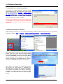
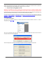
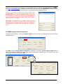
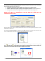
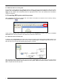
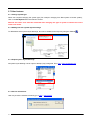
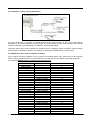
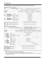
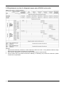
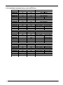
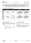
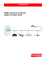
User Manual AMDS Selection Software Digital Variable Multi Table of Content 1.0 Introduction to Selection Process…..……………………….………………………………....1 1.1 Study the floor plan layout and confirm the conditioned space…………..………..1 1.2 Select the locations available for outdoor units and indoor units..……….………..1 1.3 Select the model for indoor unit…………………………….………………………….1 1.4 Partition the air conditioning system ...…………………………………………….....1 1.5 Calculate the occupying area of each indoor unit.…………………………………..2 1.6 Selection through Software……………………………………………………………..2 1.7 Output selection report……………………………………………………………….…2 2.0 Software Operation……………………………………………………………………………..3 2.1 Installation of selection software………………………………………………………3 2.2 Start the selection software…….………………………………………………………3 2.3 Create new project……………...…………………………………………………..…..4 2.4 AMDS system selection process……………………………………………….…….5 2.4.1 Selection base on area………………..……………………………………..7 2.4.2 Selection base on cooling load………………….……………………………8 2.5 Completing AMDS system selection process………………………………………...8 2.5.1 Selection with Calculation tab…………………………………………….…8 2.5.2 Selection with Quick Calculation tab…………………………………………9 2.6 Output selection report……………………………………………………..…………..9 2.7 Other features…………………………………………………………………….……10 2.7.1 Change system type………………………………………………………...10 2.7.2 Adding text into system layout drawings………………………………….10 2.7.3 Output system layout drawings……………………………………………10 2.7.4 Version information………………………………………………………….10 2.7.5 Locking function for indoor unit selection…………………………………11 2.7.6 Password changing………………………………………………………….11 2.7.7 Unit changing…………………………………………………………………11 2.8 Error messages…………………………………………………………………………11 2.8.1 Imbalance cooling capacity distribution……………………………………12 2.8.2 Maximum indoor units connectable exceeded……………………………12 2.8.3 Can’t get proper refnet or distributor………………………………………13 2.8.4 Piping length exceeds limitation……………………………………………13 2.8.5 Input piping length……………………………………………………………14 2.8.6 Unreasonable unit selection…………………………………………………14 3.0 Appendix…………………....…………………………………………………………………..15 3.1 Requirements on size of refrigerant copper pipe of R22 series units.......……….15 3.2 Requirements on size of refrigerant copper pipe of R410A series units…………16 3.3 Dimensions of refnet and distributor………………………………………………...17 3.4 Combination between indoor unit and EXV box………….………...……………….18 This manual is prepared based on the latest version of AMDS Selection Software at that time (Digital Variable Multi Version 3.3). Please take note that any AMDS Selection Software that is older than current latest version will not be supported by OYLM. ! Caution Please retain this manual carefully for further reference if there is any problem 1.0 Introduction to Selection Process 1.1 Study the floor plan layout and confirm the conditioned space First, obtain the architectural base drawing or building floor plan layout from the client. Study the drawing carefully and determine the conditioned and unconditioned space. 1.2 Select the locations available for outdoor units and indoor units Review the site and communicate with client. Then, select the locations for outdoor units and indoor units inside the conditioned space. For example, outdoor and indoor units can be located in shaded area . 1.3 Select the model for indoor unit Select suitable model for indoor unit according to the function and requirement of each air conditioned space. The table below shows the indoor unit models offered by Acson, together with their capacity respectively. Model Ceiling concealed Ceiling cassette High static ducted blower Ceiling convertible Wall mounted ACCD/A5CCD ACKD/A5CKD ADBD ACMD/A5CMD AWMD/A5WMD Capacity Range (kW) Cooling Heating 2.8 – 16.4 3.2 – 18.5 2.8 – 14.0 3.2 – 16.0 22.4 – 28.0 25.0 – 31.5 3.6 – 16.4 4.0 – 18.5 2.5 – 6.5 2.8 – 7.4 1.4 Partition the air conditioning system Decision has to be made on how many air conditioning systems are needed to condition the building. Divide the building into several partitions of air conditioning systems and set the connection sequence of indoor units according to the distance and location relative to outdoor unit. DVM User Manual 2012 1 1.5 Calculate the occupying area of each indoor unit Calculate the occupying area of every indoor unit. It is important to take into account on the heat load within the conditioned space. 1.6 Selection through Software Select the outdoor model by entering information such as piping length, indoor models, system layout and design condition. Through the selection software, piping diameter, refnet and distributor will be selected. 1.6 Output selection report After completion of selection, report can be output in excel or PDF format for ordering. 2 DVM User Manual 2012 2.0 Software Operation 2.1 Installation of selection software The installer for AMDS Selection Software (Digital Variable Multi) can be downloaded from e-Biz. Kindly login to e-Biz and go to e-Product > System Selling Kit > Multi Digital Scroll > Selection & Commissioning Software to download the file. During installation, kindly choose the desired location (refer to diagram on the right) and click “Next” to continue. Remark: If the software does not work normally when it is installed on the system disk, kindly uninstall the software and re-install it in disk location other than system disk. 2.2 Start the selection software After installing the software, run the selection software by double-click the desktop shortcut icon. Alternatively, it can be run by go to Start > Programs > Digital Variable Multi Software > Digital Variable Multi. During start-up of the software, a login window will be prompt. Kindly enter your username and password accordingly. If internet connection is available, please ensure the CheckNet is ticked before clicking OK to use the software (refer to diagram on the right). If internet connection is not available for the moment, uncheck the CheckNet dialogue box before log in. When there’s any update, an update dialogue box will prompt out and begins to download the necessary files to update the software’s database. Once update is completed, users have to login again in order to use the software. If there’s no update available, the software will enter the selection page directly. DVM User Manual 2012 3 Please note that during first time login, internet connection is a must as the software needs to update the product database before usage. Besides that, username will be terminated if: User never login into the software for 90 days. User did not login with CheckNet for 60 days. Remark: It is advisable for user to connect to the internet and tick the “checknet” dialogue during every login. This is to ensure the software database is up-to-date in order to avoid any wrong selection. If you are unable to connect to the server, kindly ensure that you are running the software as administrator and also ensure connection to the server (IP: 210.75.20.9) is not blocked by any firewall. For users who wish to register for Username and Password, kindly download the User Application Sheet from e-Product > System Selling Kit > Multi Digital Scroll > Selection & Commissioning Software, fill up and sent to [email protected]. 2.3 Create new project After login into the selection software, you will be prompt with the selection software’s interface. To create a new project, go to File > New. Next, key in the desired project name (file name) and click OK. You may select the location where the files for this project will be saved (as highlighted). Select the appropriate system type according to refrigerant and design temperature requirement. 4 DVM User Manual 2012 Under this project folder, user may starts to create AMDS systems by clicking Unit Management icon or go to Unit > Unit Management. A dialogue box will pop up, fill in the name of the New Unit (For example: CDU01) and click “New” to proceed to the interface of unit selection (refer to diagram below). Remark: If user wants to rename the system, simply select the Unit Name, and then key in the desired name in the Rename Unit column and click Rename. Similarly, user may delete a system by selecting the system and click Delete and copying a system by selecting Copy (useful when creating similar system in one project). Please take note that renaming of system name can only be done within the software. If user rename the project file manually without using this software, the file will no longer be recognized by the software and it will failed to be opened in future. 2.4 AMDS system selection process To begin with the selection, click on the MDS tab to diagram below). in the tool bar and a new dialogue box will pop up (refer Click Edit to set the Cooling Capacity Reference according to city location. Cooling Capacity Reference for some city is already available. User may select directly if appropriate. If desired city is not within the list, user can add in new reference by clicking Add. DVM User Manual 2012 5 After selecting the Cooling Capacity Reference, click OK to proceed to next screen. Here, users have to define the basic parameter of the outdoor unit: Unit Selection: Determine the model of AMDS system (cooling only or heatpump model) Height Diff.: Determine the position of outdoor and height difference between outdoor and indoor unit. I/O Ratio: Determine the designed input/output ratio. Range from 100-120%. Cooling Condition: Determine the design ambient and indoor condition under cooling mode. Heating Condition: Determine the design ambient and indoor condition under heating mode. Remark: For I/O Ratio, it is recommended to set as 100%. Please do not select 120% if the simultaneous use factor is high. Remark: Positive Height refers to outdoor installed above indoor units, while Negative Height refers to indoor installed above outdoor unit. After selecting the Basic Parameter for outdoor unit, click OK to proceed. The mouse cursor will now turn into an icon of AMDS outdoor unit. Simply click on the empty selection space to continue. Selection continues with inserting the refnet or distributor joint to the drawing. This can be done by clicking refnet or distributor icon. The mouse cursor will turn into the icon of refnet or distributor, and user can now construct the system frame work step by step according to the designed layout of indoor and outdoor unit. Simply click the square boxes to place the refnet or distributor into the system. 6 DVM User Manual 2012 After the system framework is finished, select the indoor units according to project requirement. Select desired indoor models by clicking the tab on top (refer to figure below, highlighted), follow by clicking the square box within the selection space to place the indoor unit into the system. To complete indoor model selection, double click on the icon of the respective indoor unit and a new window will pop out. Here, user can choose to complete the indoor unit selection by any of the two methods: 2.4.1 Selection base on area By using this method, users are requested to enter information such as: Room Name: Name of the conditioned room Area: Area of the conditioned room Facing Direction: The conditioned room’s facing direction (North, East, West, South) Floor Number: Floor specification for the conditioned space. Function: Function of the conditioned space. This will determine the cooling load required. After entering this information, click Apply and the recommended indoor unit will be displayed in the Model section. Click OK to select the indoor. DVM User Manual 2012 7 2.4.2 Selection base on cooling load If the specific cooling load for the conditioned space is known, user may use this method to select for indoor models. First, select base on cooling load and enter the Cooling Load into the dialogue box. Next, click on Apply and the software will automatically select an appropriate indoor unit for the required load. Click OK to confirm the selection. 2.5 Completing MDS system selection process After completing the selection for indoor units, the outdoor unit needs to be selected. This is done by clicking the Calculation icon in the toolbar. There are two calculation tabs in the toolbar. On the left is the Calculation tab while on the right is the Quick Calculation tab. User may choose to use either tab to select the outdoor unit. 2.5.1 Selection with Calculation tab In order to use the Calculation tab, users have to enter the length of each piping within the MDS system. This can be done by moving the mouse cursor over the value of piping length. The piping length value will turn into blue and user can now enter their desired piping length to continue. After all piping length is determined, user can now click the Calculation tab in the toolbar and a new window will prompt with recommended outdoor selection for this system. Select the desired outdoor model and click OK to complete the selection process. 8 DVM User Manual 2012 2.5.2 Selection with Quick Calculation tab If user uses Quick Calculation to select for outdoor unit, a new window will prompt out. Here, users have to input the length of the longest branch within the system in Last Length and click OK. A new window will prompt with recommended outdoor selection for this system. Select the desired outdoor model and click OK to complete the selection process. 2.6 Output selection report Upon completion of the selection process, user can choose to generate a report for this selection in either PDF or Excel format. Simply go to Unit > PDF Report or Excel Report. Next, user can choose to select refnet with insulation or without insulation and click OK to generate the report. DVM User Manual 2012 9 2.7 Other features 2.7.1 Change system type When user requires changing the system type (For example: changing from R22 system to R410A system), click on the Set System tab in the toolbar to reset it. Remark: All indoor units must be reselected after changing the type of system to obtain the correct indoor unit model. 2.7.2 Adding text into system layout drawings To differentiate each system layout drawings, text can be added into the layout by using the Text tab . 2.7.3 Output system layout drawings All system layout drawing can be output to bitmap (.bmp) image file. Go to File > Save As Bitmap File. 2.7.4 Version information User may check the software version by go to Help > About MDS. 10 DVM User Manual 2012 2.7.5 Locking function for indoor unit selection To prevent the indoor unit model to change under any circumstance, user can choose to tick on Appoint Indoor checkbox when selecting indoor unit. 2.7.6 Password changing To ensure the software is protected and used only by authorized personnel, the password of the software can be changed manually. Go to User Name > Change Password. User will have to enter the existing password before changing to the new password. After the password is changed, kindly inform the software administrator through this e-mail address: [email protected] 2.7.7 Unit changing User may change between metric and imperial unit by go to Unit > Imperial Unit or Metric Unit. 2.8 Error messages When designing MDS system, there are a few limitations which have to be taken into consideration: Maximum connectable indoor Piping length limitation Refrigerant distribution limitation Please refer to appendix for detail tables and description on each limitation. Once a selection has exceeded the limitation, error message will pop out to request user to amend the system design. DVM User Manual 2012 11 2.8.1 Imbalance cooling capacity distribution For every refnet joint in a system, the smaller branch shall occupy at least 10-15% of the total capacity distributed by that refnet (depends on piping length and overall system layout), while the larger branch shall sustain the remaining. If the distribution is imbalance, a warning will appear. Taking the figure above as an example, the smaller branch is supplying 3.6kW of capacity, while the larger branch supply for 32.8kW of capacity. The capacity occupied by the smaller branch is around 10% 2.8.2 Maximum indoor units connectable exceeded Every outdoor unit has its limitation on the maximum connectable indoor units. Please refer to the following table for indoor quantity limitation. If the selected value exceeds the limit, the following message will appear: For example: MDS240 indoor unit amount cannot exceed 24. R22 Model AMDS 30A(R) AMDS 40A(R) AMDS 50A(R) AMDS 60A(R) AMDS 70A(R) AMDS 80B(R) AMDS 100B(R) AMDS 120B(R) AMDS 150B(R) AMDS 180B(R) AMDS 200B(R) AMDS 220B(R) AMDS 240B(R) AMDS 260B(R) AMDS 280B(R) AMDS 300B(R) AMDS 320B(R) 12 R410A Model A5MDS 50B(R) A5MDS 60B(R) A5MDS 70B(R) A5MDS 80B(R) A5MDS 100B(R) A5MDS 120B(R) A5MDS 140B(R) A5MDS 160B(R) A5MDS 180B(R) A5MDS 200B(R) A5MDS 220B(R) A5MDS 240B(R) A5MDS 260B(R) A5MDS 280B(R) A5MDS 300B(R) A5MDS 320B(R) A5MDS 340B(R) A5MDS 360B(R) A5MDS 380B(R) A5MDS 400B(R) A5MDS 420B(R) A5MDS 440B(R) A5MDS 460B(R) A5MDS 480B(R) A5MDS 500B(R) Maximum Indoor Quantity 5 6 8 9 11 13 16 16 20 20 20 24 24 24 24 32 32 32 32 36 36 36 38 38 38 38 38 38 DVM User Manual 2012 2.8.3 Can’t get proper refnet or distributor This error will appear when the software is unable to select a refnet/distributor that meets the requirement of the selection. This error rarely occurs. However, if such error occurs, adjust the cooling capacity ratio between the branches of the refnet/distributor. 2.8.4 Piping length exceeds limitation When the designed system’s piping length has exceeded the limitation of AMDS system, an error message will appear. Please design the system according to the piping limitation stated as below. Remark: When the longest piping branch has a length which exceeds 90% of the maximum allowable length (refer to the table below): The gas pipe connected to the unit will automatically increase by one size. The refnet pipe will be selected with the new increased size automatically. A warning message will appear. R-22 Length (m) Total equivalent length Piping Height R-410A 3-5HP 6-7 HP 8-32 HP 5HP 6-7 HP 8-50 HP 100 150 350 100 150 500 Actual piping length 50 70 125 50 70 150 Equivalent length 60 80 150 60 80 175 Maximum equivalent length from first branch to furthest unit 25 30 40 25 30 65 outdoor above 20 30 50 20 30 50 indoor above 20 30 40 20 30 40 Maximum length of longest branch Between further indoor and outdoor Maximum height between indoor unit 15 Height between further indoor and outdoor Maximum length of longest branch DVM User Manual 2012 Maximum height between indoor units 13 2.8.5 Input piping length When user want to use the Calculation tab to select the outdoor unit, the length of every piping has to be enter into the selection drawing. If there is any piping length that is not defined, the error below will show. Kindly locate the piping in red and enter the piping length before proceed to outdoor unit selection. 2.8.6 Unreasonable unit selection When ducted blower is selected within an AMDS system, other indoor unit should not have capacity lower than 27,000 Btu/h. If unit with capacity lower than that is selected, the following error will show. Kindly re-select the indoor unit accordingly. 14 DVM User Manual 2012 3.0 Appendix 3.1 Requirements on size of refrigerant copper pipe of R22 series units Specification table for MDS-A Series Specification table for MDS-B Series Remark: 1. Pipe thickness selection is based on certain material in GB/T1527-1997. If using different material, design pressure must be 3.0 MPa according to local standard. 2. If the units are installed in corrosive environment, the pipe must be 0.2mm thicker. 3. This list shows only the minimum thickness. Bending or stretching may reduce the thickness, please consider the compensation. DVM User Manual 2012 15 3.2 Requirements on size of refrigerant copper pipe of R410A series units Specification table for 5MDS-B Series Remark: 1. Pipe thickness selection is based on certain material in GB/T1527-1997. If using different material, design pressure must be 4.15 MPa according to local standard. 2. If the units are installed in corrosive environment, the pipe must be 0.2mm thicker. 3. This list shows only the minimum thickness. Bending or stretching may reduce the thickness, please consider the compensation. 16 DVM User Manual 2012 3.3 Dimensions of refnet and distributor DVM User Manual 2012 17 3.4 Combination between indoor unit and EXV box Indoor Model AWMD 09G AWMD 10G AWMD 15G AWMD 20G AWMD 25G 18 Liquid Pipe Diameter (Inch) R-22 R-410A 1/4 1/4 1/4 1/4 1/4 1/4 1/4 1/4 3/8 1/4 AEX Model R-22 R-410A AEX-15-2SAP-D AEX-15-2SAP-D AEX-15-2SAP-D AEX-18-2SAP-D AEX-18-3SAP-D AEX-22-2SAP-D ACKD 10C ACKD 15C ACKD 20C 1/4 1/4 1/4 1/4 1/4 1/4 AEX-15-2SAP-C AEX-15-2SAP-C AEX-18-2SAP-C ACKD 20A ACKD 25A ACKD 30A ACKD 40A ACKD 50A 1/4 3/8 3/8 3/8 3/8 1/4 1/4 3/8 3/8 3/8 AEX-18-2SAP-C AEX-18-3SAP-C AEX-22-2SAP-C AEX-24-3SAP-C AEX-22-3SAP-C AEX-24-3SAP-C AEX-22-3SAP-C AEX-24-3SAP-C AEX-22-3SAP-C ACCD 10C ACCD 15C ACCD 20C ACCD 25C ACCD 28C ACCD 30C ACCD 38C ACCD 40C ACCD 50C ACCD 60C 1/4 1/4 1/4 3/8 3/8 3/8 3/8 1/2 1/4 1/4 1/4 1/4 3/8 3/8 3/8 3/8 3/8 3/8 AEX-15-2SAP-C AEX-15-2SAP-C AEX-18-2SAP-C AEX-18-3SAP-C AEX-22-2SAP-C AEX-22-3SAP-C AEX-24-3SAP-C AEX-22-3SAP-C AEX-22-3SAP-C AEX-24-3SAP-C AEX-22-3SAP-C AEX-24-3SAP-C AEX-22-3SAP-C AEX-24-4SAP-C AEX-24-3SAP-C ACMD 15E ACMD 15E ACMD 15E ACMD 15E 1/4 3/8 3/8 1/4 1/4 1/4 3/8 AEX-15-2SAP-C AEX-18-2SAP-C AEX-18-3SAP-C AEX-22-2SAP-C AEX-18-3SAP-C AEX-22-3SAP-C ACMD 40D ACMD 50D ACMD 62D 3/8 3/8 1/2 3/8 3/8 3/8 AEX-24-3SAP-C AEX-24-3SAP-C AEX-24-4SAP-C ADBD 80 ADBD 100 1/2 1/2 1/2 1/2 - AEX-22-3SAP-C AEX-22-3SAP-C AEX-24-3SAP-C Built-in EXV available Built-in EXV available DVM User Manual 2012 While upmost care is taken in ensuring that all details in the publication are correct at time of going to press, we are constantly striving for improvement and therefore reserve the rights to alter model specifications and equipment without prior notice. Details of specifications and equipment are also subject to change to suit local conditions and requirements and not all models are available in every market.