1
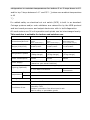
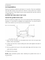
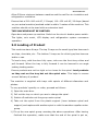
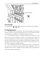
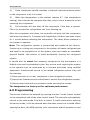
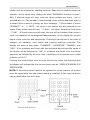
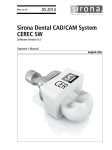
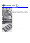
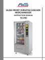
DVCM130323V1
CONTENTS
1.0 DESCRIPTION…………………………………………………………………………………1
2.0 INSTALLATION………………………………………………………………………………2
3.0 LOADING OF PRODUCT…………………………………………………………………2
4.0 COINAGE…………………………………………………………………………………………4
5.0 REFRIGERATION……………………………………………………………………………4
6.0 PROGRAMMING………………………………………………………………………………6
6.1 MANUAL TUBE FILLING(FILL COIN)………………………………………………7
6.2 PRICE SETTING (SET PRICE)…………………………………………………………7
6.3 SINGLE MOTOR TEST (SINGLE SELECTION)……………………………….8
6.4TEST ALL MOTORS (ALL SELECTION)………………………………………….8
6.5 ACCOUNTABILITY (ACCOUNT)………………………………………………………9
6.6 VEND OPTIONS (OPTIONS PUSH[#])……………………………………………….…10
7.0 CLEANING……………………………………………………………………………………21
8.0 MAINTAINANCE……………………………………………………………………………21
9.0 NOISE………………………………………………………………………………………….22
10.0 RESTRICTIONS OF USE………………………………………………………………22 11.0
IMPORTANT SAFEGUARDS…………………………………………………………22
APPENDIX TROUBLESHOOTING…………………………………………………………25
DVCM130323V1
1.0 Description
This machine is a chilled spiral merchandiser. It has 6 trays – 3 or 4 snack
spiral trays & 3 or 2 drink trays.
The machine’s robust construction makes it ideal for many locations. The
machine has superior insulation, a double glazed window. Meanwhile, it has
two temperature compartment (top and bottom). It has no problem for the
refrigeration to maintain temperatures for bottom 3 or 2 trays down to 8℃
and for top 3 trays between 14℃ and 25℃. )(when max ambient temperature
is 40
℃)
For added safety an electrical cut out switch (RCD) is built in as standard.
Coinage systems and/or note validators are catered for by the MDB protocol
and two board processor and output electronics with in built diagnostics.
All vend motors are 24 volt operation and spirals can be interchanged easily.
This machine is suitable for indoor and outdoor use.
Model
VCM-3000
VCM-4000
VCM-5000
Weight( N.W/G.W)
762 X 830×1830
(mm)
30 X 32.6×72(in.)
285Kg/305Kg
628Ibs/672Ibs
890 X 830×1830(
mm)
35 X 32.6×72(in.)
320Kg/340Kg
705Ibs/750Ibs
1056 X
830×1830(mm)
41.6 X 32.6×72(in.)
350Kg/380Kg
771Ibs/838Ibs
Max selections
36
48
60
Refrigeration system
1/2 HP R-134a
(280g charge)
1/2 HP R-134a
(370g charge)
3/4 HP R-134a
(370g charge)
Power Consumption
650W
650W
845W
Dimensions(W×D×H)
AC 220V~240V 50Hz /AC 110V~130V 60Hz
(based on your actual machine)
12VDC LED Color corrected lighting system
Power Supply
Lighting (Optional)
Internal
temperature
1 x 15 watt Fluorescent
Top
14 ℃ ~ 25 ℃
Bottom
Down to 8℃
1 x 18 watt
Fluorescent
Coinage system
M.D.B.
Air noise
Less than 60dB
Conditions of use
Ambient temp 0 ~ 40 ℃
Humidity 70%
Outdoor protection from direct sun & rain.
Not for dairy or perishable goods.
1
DVCM130323V1
2.0 Installation
Remove all packing materials and dispose of correctly. Once the installation
site has been chosen ensure that the machine is level and all four levelers
touch the ground. Check that the door can be opened fully and the machine
is stable and level.
MACHINE MAY MISS-VEND IF NOT LEVEL
Install the guided wind cover
We don't install the guided wind cover of the machine before leaving factory,
because it is convenient for package and transportation. You should install it
before the machine is put into service as the following:
1) Open the door and take out the guided wind cover from the right small
drawer of the merchandiser.
2) Loosen the lower four screws holding the wind outlet against the back of
the cabinet.
3) Put the guided wind cover to the wind outlet align with the holes in the
outlet and the cabinet.
4) Fasten the four screws
NOTE: Wear protective gloves when installing the guided wind cover to
prevent injury.
2
DVCM130323V1
Allow 300mm minimum between machine and the wall for air circulation and
refrigeration ventilation.
Ensure that a 220~240 volt AC, 13 Amps/ 110~130 volt AC, 26 Amps (based
on your actual machine) earthed outlet is within 2 meters of the machine. This
machine should not be used with an extension lead.
THIS MACHINE MUST BE EARTHED
Open door and power up machine. Switch on the circuit -beaker power switch.
The lights, coin mech, LCD display and refrigeration system commence
operation.
3.0 Loading of Product
This machines have 6 trays. The top 3 trays are for snack type/size items such
as chips, chocolate, etc.. The bottom 3 trays are for drink type/size items as
bottle or can.
To load a tray, with the door fully open, ride over the front tray rollers and
pull forward. When the tray is fully forward it can be lowered to an angle
making loading easier.
Ensure products are not too tight or too loose for the spiral. Load products
so they rest on the tray but not the spiral wire. This helps to ensure
correct delivery of product.
The machine is supplied with trays with spirals of different diameters and
pitches.
To vary products’ quantity or order, proceed as follows:
1) Open the main door.
2) Pull out the tray on which you are to change the spiral.
3) Switch off and take out the group motor-spiral.
4) Take out the spiral from the plastic support (lever between spiral and
support) and replace with another spiral or with the another expeller motor
group.
1) Fit up the new spiral group reversing the above operations. After having
finished this operation, make sure that the end of the spiral is put on,
DVCM130323V1
otherwise modify the end, draw the spiral forward until the base of the
spiral support will come out from the pit; then turn the spiral in the wished
3
position and put it again into the pit.
Located on the right hand side of the cabinet are four pull out drawers for
storing any excess items. Although the drawers are outside the refrigerated
part of the machine, due to the excellent insulation they are protected from
high ambient temperatures.
Note: Please take care of your hand when you close the door.
Do not exceed the protective plate!!!
ProtectivePlate
√
4
DVCM130323V1
ProtectivePlate
×
4.0 Coinage
This machine uses Multi Drop Bus protocol for coinage and note validators.
5.0 Refrigeration
1)
This system is an air conditioner. Care should be taken not to obstruct
the rear air grille or to site the machine too close to a wall. Failure to observe
these points may invalidate the refrigeration system warranty.
2)
The refrigeration system is operated through the electronic control
board. There are two temperature sensors in the cabinet: one control the
current temperature, the other control the defrost temperature. When an
unusual condition takes place and leads to the fact that the evaporator frosts,
the sensor will send out a signal to the controller, then the controller in turn
shut off the compressor through the relay.
3)
If the temperature is above the setting that has been programmed in
by the user, the controller sends a signal to the refrigeration relay. The
energized relay closes to complete the high voltage circuit that powers the
compressor and the condenser fan.
5
DVCM130323V1
4)
If the compressor should overheat, a thermal overload removes power
to the compressor until it is cooled.
5)
When the temperature in the cabinet reaches 8℃ (the temperature
setting), the controller de-energizes the relay, which in turn breaks the circuit
powering the compressor.
6)
The controller will also shut off the compressor if the door is opened.
This is to prevent the refrigeration unit from freezing up.
After the compressor shut down, the controller will wait until the compressor
has been shut down for 3 minutes and if applicable, the door has been closed
for 1 minute before restarting the compressor. The delay allows pressure in
the system to equalize.
Note: The refrigeration system is pressurized and sealed at the factory.
Puncturing or cutting any component in the system will cause refrigerant gas
and liquid to be propelled out of the system, and may create an immediate
physical hazard. Use caution to avoid accidentally opening the refrigerant
system.
It should also be noted that releasing refrigerant to the atmosphere is a
federal crime and is punishable by law. Any service work requiring the system
to be opened must be performed by a licensed technician using certified
equipment. Unauthorized service to the sealed refrigerant system may void
the warranty.
1) Never puncture or cut any component in the refrigeration system.
2) Always use licensed service technicians to service the refrigeration system.
3) Always wear hand and eye protection when servicing the vendor.
The temperature is factory set for optimum performance.
6.0 Programming
The service mode can be entered by pressing the blue "mode" button located
on the component side of the main control board. The controller automatically
returns to the sales mode if the door is closed. If credit exists before entering
the service mode, it will be restored when the sales mode is re-invoked. When
opening the door, the MDB machine (coin mechanism and bill acceptor or card
6
DVCM130323V1
reader) will be inhibited by vending machine. Beep will be made to alarm the
operator. At the same time, display will show “WARNING: the door is open”.
After 2 seconds beep will stop, and only those motors not home , null or
jammed will run. The number of the selected motor will be displayed when it
is tested. After a motor’s running, an error message ' **(the number of motor
)TIMEOUT! ' or ' ** LOST! ' will show if any motors are still jammed or not
home. If any motors are still null, ' ** NULL ' will show. Otherwise it will show
' ** OK! ' . If those motors are all reset, the test will be finished. After motor’s
reset, the machine will be diagnosed automatically. It will display the current
status of the controller and peripherals. Checking is carried out in the order of
changer, bill validator, card reader and vending machine controller. The
display will show in this order: "CHANGER", "VALIDATOR", "READER", and
"VMC". If no problems are found with the individual device then the name of
the device will be followed by "OK". If problems are found then the device
name will be followed by an error code. A definition of all possible error codes
is shown in 6.6.17.
Pressing the mode button once to enter the service mode, the transition and
the display will indicate the first service menu item as “#SERVICE MODE# PLS
PRESS ENTER”.
NOTE: If the control board need to be replaced for some reasons, all motors
must be tested after the new control board is installed. In this way the motor
can be reset when the door open.
7
DVCM130323V1
The operator navigates the service menu by using above 3 function buttons.
The "*" button may be thought of as a "DOWN” button .For entering into a
given menu item, the user should press the "#" button. It's easy to think of
this "#" button as the "ENTER" button. To cancel navigation within a menu
item and return to the previous level, the user should press the “ C ” button.
This button may be thought of as the "CANCEL" button. At specific points in
the menu the user is given the option of saving a setting. A press of the "#"
button has another effect as the "SAVE" button. For the purpose of simplifying
the service mode instructions, the following will introduce details and
emphasize their navigation purpose within the service menu.
6.1 Manual Tube Filling (FILL COIN)
This provides functions of manually filling and dispensing coins for the changer.
This function is started by pressing "#" after the user entering the menu item
labeled "FILL COIN". At this time, the operator may begin inserting coins into
the changer. When coins enter, display will show the total value of the coins
entered as “CASH **(present sum of coin the operator inserted in), CHANGE
**(present available change coin of the coin mechanism)”
6.2 Price Setting (SET PRICE)
This menu provides functions that allow the operator to set prices for individual
selections. Pressing “*”button when it displays” FILL COIN”, the menu item
will labels "SET PRICE”.
Press "#" to enter the menu. Select which set of prices you wish to change.
Enter the selection. This can include * as a wildcard. eg.
1* - set all items on tray 1 to the same price
*0 - set all items in the first column to the same price
** - set all items in the machine to the same price
To set the price of a single selection the user should enter the number of the
selection by the keyboard. Then it will display “SEL ** (the number of selection
the user have entered)”, next the user should enter the price of the selection
by the keyboard. If the operator is satisfied, the "#" button should be pressed
8
DVCM130323V1
to proceed with the current price setting. If the operator is not satisfied with
the selection(s) or if he/she wants to exit the menu then the “C” button should
be pressed and it will return to the previous menu.
6.3 Single Motor Test (SINGLE SELECTION)
This menu provides functions that allow the operator to test the operation of
individual motors. After pressing “*” button when it displays” SET PRICE”, the
menu item will labels " SINGLE SELECTION”.
Upon entering into the function, the display will show “SELECT ** “.To test a
single motor the user should enter the required selection number by the
keyboard. Then it will display”** (the number of motor the user entered)
TESTING”. If the motor is working,”** OK” will be showed, otherwise “**
ERROR” will be showed. If the motor does not exist “** (the number of motor)
NULL” will be showed. To exit the menu please press “C” button.
6.4 Test all Motors (ALL SELECTION)
This menu provides functions that allow the operator to test the operation of
all motors. After pressing “*”button when it displays “SINGLE SELECTION”,
the menu item will labels " ALL SELECTION”.
Upon entering into the function, if any motor is not working, “** (the number
of motor that has error) ERROR!” will be showed. If the motor does not exist
“** (the number of motor) NULL” will be showed, then go on to the next motor
test. If all motors are working, “ALL OK” will be showed. To exit the menu
please press “C” button.
6.5 Accountability (ACCOUNT)
This menu provides functions of displaying the stored accountability. After
pressing “*”button when it displays “ALL SELECTION”, the menu item will
labels "ACCOUNT". To enter it please press the "#" button. To exit this menu
or any of the functions within this menu, the “C” button should be pressed.
6.5.1 Historical Sales (HIST SALES)
Display value of all paid sales since initialization.
9
DVCM130323V1
6.5.2 Historical Count (HIST COUNT)
Display total number of products vended since initialization. 6.5.3
Resettable Sales (RES SALES)
Display value of all paid sales since the last reset.
6.5.4 Resettable Count(RES COUNT)
Displays total number of products vended since the last reset.
6.5.5 Card Reader Sales (CARD SALES)
Display value of total card reader sales since initialization.
6.5.6 Resettable Card Count(RES CARD )
Display value of all card sales since the last reset
6.5.7 Defined Sale Account (SINGLE ACCOUNT)
This allows the user to set a single product that will be tracked for accounting
purposes. Once enter this menu item, the user will see a display as "SELECT
**". The user can set the product number, then it will display total number of
products vended of the chosen product.
6.5.8 Clear all Resettable Fields (CLEAR)
This function allows the user to set all resettable fields to 0.
Upon entering this function, those resettable items will be cleared and the
display will show "FINISHED".
6.6 Vend Options (OPTIONS PUSH [#])
This menu provides functions that allow the operator to control a variety of
vending options. After pressing “*”button when it displays “ACCOUNT”, the
menu item will labels "OPTIONS PUSH[#]”. Pressing the "#" button to enter
it. To exit this menu or any of the functions or submenus within this menu,
the “C” button should be pressed. Press”#” button to enter the following
functions.
10
DVCM130323V1
6.6.1 Force Vending (FORCE VEND)
This option will force the customer to complete a purchase once they deposit
money of any form. If a vend is attempted on a configured selection and the
motor fails during this vend, the customer will be allowed to escrow the credit,
regardless of the force vend status.
Upon entering this function the display will show the current on/off state as
"ON" or "OFF ". Pressing "#" will allow to enter into the edit mode, then press
the “*”button to switch the on/off state. At last the user should press ”#”
again to save the conversion. At any time, the function may be exited by
pressing “C” button.
6.6.2 Multiple Vending (MULTI VEND)
This option will allow the customer to purchase more than one product if
enough credit has been deposited. When this function is active, any remaining
credit after a vend will not automatically be returned. At this time, the
customer has the option of:
1) Making another selection if there's enough credit;
2) Depositing more money;
3) Escrowing the remaining credit.
If force vend is active, the customer will be forced to attempt the purchase of
at least one valid (the selection is in configuration) item. If a vend is attempted
on a configured selection and the motor fails during this vend, the customer
will be allowed to escrow the credit, regardless of the force vend status. Upon
entering this function the display will show the current on/off state as "ON" or
"OFF ". Pressing "#" will allow to enter into the edit mode, then press the
“*”button to switch the on/off state. At last the user should press ”#” again
to save the conversion. At any time, the function may be exited by pressing
“C” button.
6.6.3 Test Vending (VEND TEST)
This menu provides functions that allow the operator to test vending whether
to be recorded or not. Press the "#" button after the user has navigated to
11
DVCM130323V1
the menu item labeled “VEND TEST” to enter it. The display will show “ON “or
“OFF”. This initial ON/OFF status indicates if the corresponding control is active
or inactive. Pressing "#" will allow to enter into the edit mode, then press the
“*”button to switch the on/off state. At last the user should press ”#” again
to save the conversion. At any time, the function may be exited by pressing
“C” button.
6.6.4 Free Vending (FREE VEND)
This menu allows free products to be given to the customer. Every product
will be vended at no cost. When the status is "ON", the MDB machine (coin
mechanism and bill acceptor or card reader) will be inhibited by vending
machine. Upon entering this function the display will show the current on/off
state as "ON" or "OFF ". Pressing "#" will allow to enter into the edit mode,
then press the “*”button to switch the on/off state. At last the user should
press ”#” again to save the conversion. At any time, the function may be
exited by pressing “C” button.
6.6.5 Escrow the Bill (BILL ESCROW)
This menu provides functions that allow the last bill accepted in the escrow
position no matter to be returned or not. When this function is active and the
bill acceptor offers escrow, bill acceptance is disabled if the accumulated credit
is greater than or equal to the maximum price (or twice the maximum price
when multi vend is active). The bill will be kept in the escrow position, and it
can be returned, otherwise the bill will go straight into the bill stacker.
Upon entering this function the display will show the current on/off state as
"ON" or "OFF ". Pressing "#" will allow to enter into the edit mode, then press
the “*”button to switch the on/off state. At last the user should press ”#”
again to save the conversion. At any time, the function may be exited by
pressing “C” button.
6.6.6 Record of Last Sale(SALES RECORD)
This menu provides functions that allow the operator to read the latest sale
record. The display will show “CREDIT***.** CARD***.** CHANGE***.**
12
DVCM130323V1
SELECTION**”(* refers to present value). This function may be exited by
pressing “C” button.
6.6.7Optical Sensor Control Options (SENSOR MODE)
There are three optional modes: DISABLE, HOME, and DROP.
DISABLE: the message 'THANK YOU" will show on the screen no matter there
is a product fall down or not.
NOTE:If the optical sensor not be installed, the detect mode must be set to
disable. When door is open, the display will show "WARNING: optic disable!".
HOME: If the product fails to vend on the first try, the spiral will automatically
make up to one additional cycles in an attempt to vend the selection. If the
product still fails to vend on the second try, a third circle will be turned. After
that if the vend still fails, message "MAKE ALTERNATE SELECTION” will be
displayed. During above process once there is a product detected, the
message “PLEASE REMOVE YOUR PRODUCT” ” THANK YOU" will show on the
screen.
DROP: If the product fails to vend, the spiral will run additional 1/6 cycle. If
there is still no product be detected, another 1/6 circle will be turned. After
that if the vend still fails, message "MAKE ALTERNATE SELECTION” will be
displayed. During above process once there is a product detected, the
message “PLEASE REMOVE YOUR PRODUCT” “THANK YOU” will show on the
screen.
Upon entering this function, pressing "#" will enable the operator to enter into
edit mode, then press the “*”button to switch the sensor mode. At last the
user should press ”#” again to save the conversion. At any time, the function
may be exited by pressing the “C” button.
When it display “MAKE ALTERNATE SELECTION”, the vend will be considered a
failure. The controller will prevent further attempts to vend the same selection.
That motor can not be vended until it is successful tested after 'MOTOR RESET'
or 'Single motor test'.(The 'MOTOR RESET' function is performed automatically
13
DVCM130323V1
after open the door, the 'Single motor test' is in the service mode.) If some
motors are failure, you can still choose anything else.
If the sale fails three continuous time under 'HOME' mode or 'DROP' mode,
the sensor will be considered has fault, the sensor mode will automatically
turn into 'DISABLE' mode. Once open the door, the display will show
"DIAGNOSE:VMC=======8=". If you set the mode to "DROP" or "HOME",
only if there is a successful vend, the count of failed sale will be cleared.
Otherwise the sensor mode will be changed afresh to "DISABLE".
6.6.8 Set Time and Date (TIME/DATE)
This option will allow the operator to set time and date for timed operations.
Upon entering this function, firstly press the “#”button, then the operator can
set the date and time by the numeric keyboard. (Note: the current time of
day is displayed in 24 hour format.) Then press “#”button again to save the
setting.
After setting time and date, if the operator press “*”button, he/she can set
the day from Sunday to Saturday. Firstly press the “#”button, then press
“*”button to choose the specific day for the vending machine. Lastly press
“#”button again to save the setting.
6.6.9 Message Programming (POS)
This submenu allows the operator customize sales messages.
Upon entering this submenu the display will show machine's current state as
"DISPLAY POS On” or “DISPLAY POS OFF". Pressing "#" will allow to enter the
edit mode, then press the “*”button to switch the on/off state. At last the user
should press ”#” again to save the conversion. At any time, the function can
be exited by pressing the “C” button.
If this function is set to “OFF”, when the machine is in the sales mode, it will
display the cabinet and defrost temperatures. If this function is set to “ON”,
the operator could choose the content of the displays. The first one is “ENJOY
A SNACK TODAY! + date & time”, the second one is “ENJOY A SNACK TODAY!
+cabinet temperature”. Pressing "#" will enable to edit the display, then press
14
DVCM130323V1
the “*”button to switch. At last the user should press ”#” again to save the
conversion. At any time, the function may be exited by pressing the “C”
button.
6.6.10 Language of Display(LANGUAGE)
This function allows the operator to choose a specific language in which sales
mode message will be displayed. In the program there are English, Italian,
Dutch, Spanish, French can be chose. Pressing "#" will allow to have the
transition of language, then press the “*”button will switch. At last the user
should press ”#” again to save the conversion. At any time, the function can
be exited by pressing the “C” button.
6.6.11 The Opening Time of Lamp (LAMP)
Upon entering this function, the display will show “STRT hh.mm". A start time
for lamp may be entered by pressing “#”and then the numeric keys; these
will be displayed as they are entered. To save, press "#"button again. The
display will next show “STOP hh.mm". A stop time for lamp may be entered
in the same way.
6.6.12Temperature Setting (TEMPERTURE)
This submenu allows the operator to activate and modify the controller's
temperature control capabilities.
6.6.12.1 Temperature Units (DEGREE)
This function allows the operator to specify the units of measurement for
temperature displaying. The display will read either "DEGREE F" for Fahrenheit
units or "DEGREE C" for Celsius units. Pressing "#" will allow to change the
unit, then press the “*”button will switch the unit. At last the user should press
”#” again to save the conversion. At any time, the function may be exited by
pressing the “C” button.
6.6.12.2 Setting Cabinet Temperature (CABINET TEMP SET)
This function allows the user to set an ideal cabinet temperature.
Cabinet temperature setting can be done in the "SET/PT" function. After
entering this function the display will show “SET/PT +00( C ". Pressing “#”
15
DVCM130323V1
and then new temperature can be input by numeric keys. Pressing "#" can
save the temperature. Pressing “C” button before "#" will exit the function
without saving the new temperature.
After finish the cabinet temperature setting, the operator should press “*” to
go the next menu to set the temperature return difference value.
"DELTA 1"
means that
when the
cabinet
temperature
exceeds the
programmed temperature (seted cabinet temperature + "DELTA 1"), the
compressor will start to run. Pressing “#” then "DELTA 1" can be entered by
numeric keys. To store the temperature value, press "#" again after it is
entered. Pressing the “C” button before "#" will exit the function without
saving.
"DELTA 2" means that if the cabinet temperature drops under the programmed
temperature (seted cabinet temperature - "DELTA 2"), the compressor will
stop running. "DELTA 2" can be entered through the same way as the setting
of “DELTA 1".
6.6.12.3 Setting Defrost Temperature (DEFROST SET)
This function allows the user to set an ideal defrost temperature.
After entering this function the display will show "TEMP 1 +00( C”. This means
at this sensor temperature the defrost cycle will start. Press “#” and enter
new temperature by numeric keys. To save the temperature please press "#"
after entered. Pressing the “C” button before "#" will exit the function without
saving the new temperature.
After finishing the setting of TEMP 1, the operator should press “*” to enter
“DELAY 1” to set the time.
When the defrost sensor temperature is under the TEMP 1 for the time of
DELAY 1, the defrost cycle will start. Press “#” and enter new time by the
numeric keys. To save the time please press "#" after entered. Pressing the
“C” button before "#" will exit the function without saving the new time.
After finishing the setting of DELAY 1, the operator should press “*”to enter
“TEMP 2”. This means that at this sensor temperature the defrost cycle will
stop. Press “#” and enter new temperature by numeric keys. To save the
16
DVCM130323V1
temperature please press "#" after entered. Pressing the “C” button before
"#" will exit the function without saving the new temperature.
After finishing the setting of TEMP 2, the operator should press “*”to enter
“DELAY 2”to set the time.
When the defrost sensor temperature exceeds the TEMP 2 for the time of
DELAY 2, the defrost cycle will stop. Press “#” and enter new time by the
numeric keys. To save the time please press "#" after entered. Pressing the
“C” button before "#" will exit the function without saving the new time.
6.6.13 Health and Safety (HEALTH GUARD)
'HEALTH GUARD' feature prevents the sale of food if the temperature inside
the machine rises above the health safety temperature limits for cold food
products for more than the time you set.
6.6.13.1 Temperature Units (DEGREE)
This function allows the operator to set the units of measurement for
temperature displaying. Display will read either "DEGREE F" for Fahrenheit
unit or "DEGREE C" for Celsius unit. Pressing "#" will allow to change the unit,
then press the “*”button to switch the unit. Then press ”#” again to save the
conversion. At any time, the function may be exited by pressing the “C button.
6.6.13.2 Sensor Control (SENSOR SET)
Upon entering this function the display will show the current state for the
sensor as "ON” or "OFF". Pressing "#" will allow to change the mode, then
press the “*”button will switch the on/off state. At last the user should press
”#” again to save the change. At any time, the function may be exited by
pressing the “C” button.
Health guard temperature can be set in the "SET/PT" function. After entering
this function the display will show “SET/PT +00( C". Press “#” and then new
temperature can be input by the numeric keys. To save the temperature
please press "#" after input.. Pressing the “C” button before "#" will exit the
function without saving.
After finish the temperature setting, the operator should press “*” to go to the
next menu to set the delay time. "DELAY 1" means that if the door is open,
17
DVCM130323V1
the start up of the health guard should be delayed by the demanded time.
"DELAY 2” means that if the cabinet temperature exceeds the programmed
temperature for this period, the relevant rows will be prohibit selling. Press
“#” and then the new time can be input by the numeric keys. To save the time
please press "#" after input.. Pressing the “C” button before "#" will exit the
function without saving.
In the rows setting menu, the user will see a display similar to "SR/ER */*".
Where “*” represents the rows to be set (row *...etc.). Press “#” and then
new rows can be input by the numeric keys. To store the rows, press "#" after
both are entered. Pressing the “C” button before "#" will exit the function
without saving the new rows.
6.6.14The Mode of Refrigeration (REFRIGERATION)
In this menu, the operator could set parameters of compressor. Pressing the
"#" button after the user go to the “REFRIGER" menu to enter it. To exit this
menu or any of the functions or submenus within this menu, the “C” button
should be pressed.
6.6.14.1 DOOR-STOP
Upon entering this function, the current running status of the compressor will
be displayed as "ON" or "OFF". Note: when it is on the “OFF” state that means
when the door is open, the compressor will go on running. Pressing "#" will
allow to change the state, then press the “*” button to switch the on/off state.
At last the user should press "#” again to save the change. At any time, the
function may be exited by pressing the “C” button.
6.6.14.2 MIN RUN
This function means that once the compressor starts, it should keep the
running state for at least the time that be set. Press “#” and then new time
can be input by the numeric keys. To save the time please press "#". Pressing
“C” button before "#" will exit the function without saving.
6.6.14.3 MIN STOP
18
DVCM130323V1
This function means that once the compressor stops, it should keep the
stopping state for at least the time that be set. Press “#” and then new time
can be input by the numeric keys. To save the time please press "#". Pressing
“C” button before "#" will exit the function without saving.
6.6.14.4 RUN TIME
If this menu is entered, the display will read “hhHmm". Here "h.m" represents
that when any of the sensor does not work or the communication between the
main control and the refrigeration board is in disable state, refrigeration cycle
must run for the time period which is set in this menu. Then the refrigeration
cycle should stop at the “STOP TIME”. Press “#” and then new time can be
input by the numeric keys. To store the time please press "#". Pressing the
“C” button before "#" will exit the function without saving.
6.6.14.5 STOP TIME
If this menu is entered, the display will change to read “hhHmm". Here “h.m"
represents that when any of the sensor does not work or the communication
between the main control and the refrigeration board is in disable state,
refrigeration cycle must stop for the time period which is set in this menu.
Then the refrigeration cycle should run at the “RUN TIME”. To store the time
press "#". Pressing the “C” button before "#" will exit the function without
saving.
6.6.15 The Information of the Machine(MACHINE INFO)
This function allows the operator to set the parameter of the machine. This
function is started by pressing "#" after the user has navigated to this menu
item.
6.6.15.1 MACHINE SERIAL
This function allows the operator to set the machine's serial. Upon entering
this submenu the display will show "VCM”. Pressing "#" will allow to set the
serial by numeric key. After finish it the user should press "#” again to save
19
DVCM130323V1
the change. At any time, the function may be exited by pressing the “C”
button.
6.6.15.2 MACHINE MODEL
This function allows the operator to set the parameter of machine model. Upon
entering this submenu the display will show ”VCM”, Pressing "#" will allow to
set the model by numeric key, after finish it the user should press "#” again
to save the change. At any time, the function may be exited by pressing the
“C” button.
6.6.15.3 SOFTWARE VER
This function will show the software version number. The function may be
exited by pressing the “C” button.
6.6.16 Call for Service (SERVICE)
It allows the operator to set the phone number when the vending machine
does not work and the customer has to call for service. Pressing "#" will allow
to set the phone number, after finish it the user should press”#” again to save
the change. At any time, the function may be exited by pressing the “C”
button.
6.6.17Diagnostics (DIAGNOSE)
The Diagnostics menu item displays the current status of the controller and
the peripherals. This menu can be entered by pressing "#" after the user has
navigated to the menu item labeled "DIAGNOSE".
The order of checking is the vending machine controller, the changer, the bill
validator, and the card reader. The display will show in this order: "VMC",
"CHANGER", "VALIDATOR", and "READER". If there's no problems with the
individual device then the relevant device name will be followed by "OK". If
there's any problems, then the relevant device name will be followed by an
error code.
A definition of all possible error codes is shown in the table below.
ERROR CODE
ERROR DESCRIPTION
20
DVCM130323V1
VMC 1
Undefined
VMC 2
Too much time to complete vend (12 seconds). For an
example, the display will show "VMC 2” if any motor in the
configuration exhibits this problem.
VMC 3
Undefined
VMC 4
Checksum error. The display would read "VMC 4".
VMC 5
Health guard operate. The display would read "VMC 5".
VMC 6
Communications fault between VMC and refrigeration unit
control board.The display would read "VMC 6".
VMC 7
Undefined
VMC 8
Eyes on the activated optical sensor are blocked.
VMC 9
Selection was not detected by optical sensor and, as such, is
considered sold out.
CHANGER 3
Loss of changer communications or no changer.
display would show "CHANGER 3".
VALIDATOR 7
Loss of bill validator communications or no bill validator. The
display would read “VALIDATOR 7".
READER 8
Loss of card reader communications or no card reader. The
display would read "READER 8".
The
7.0 Cleaning
Unplug the machine from the power before any cleaning is carried out.
7.1 Outside Cabinet
Use a soft damp cloth with a mild detergent.
Do not use a jet or water hose to clean the machine. Do not allow
water to enter the cabinet.
A propriety glass cleaner can be used on the window. Avoid using highly
perfumed products.
7.2 Inside Cabinet
Wipe cabinet and dispensing trays with a damp cloth at least once every week.
Remove all products from trays before cleaning.
Do not use a damp cloth to wipe any cables or connectors.
Use only a DRY cloth for this.
21
DVCM130323V1
Do not use a perfumed cleaning product as this may taint any snack items. If
any tray or storage drawer requires deep cleaning, remove the tray/drawer
from the machine to clean. DO not immerse any tray in water. Do not allow
water to touch motors. Ensure that tray is completely dry before re fitting.
8.0 Maintance
Disconnect the machine from the power before any maintenance is carried out.
Only qualified personnel should carry out maintenance tasks.
If the mains cable requires replacing this must be carried out by the machine
manufacturers, its agents or a qualified engineer.
Any damage to internal wiring must be repaired by a qualified engineer. Do
not remove any panel, screws fixing covers or panels. Any repairs must be
carried out only by qualified persons.
9.0 Noise
This machine has a continuously running fan within. It also has an intermittent
running refrigeration system. The noise level from this machine under normal
working conditions is slight. Any loud or persistence noise or vibration should
be reported to the service providers as this could be a symptom of a fault. Air
noise rating for this machine is 60dB.
10.0 Restrictions of Use
This version has an IP24 rating and can be used indoor and outdoors within
an ambient temperature range of 0℃~ 40 ℃.
NOTE: Use correct outdoor mains connector if the machine is to be used
outdoors.
This machine is NOT intended for dispensing dairy products, or any
perishable goods, see section 11.0
11.0 Important Safeguards
When using or maintaining electrical appliances, basic safety precautions
should always be practiced including the following:
22
DVCM130323V1
If the supply cord, lamp or leads are damaged, these must be replaced by the
manufacturer, its service agent or similarly qualified persons in order to avoid
a hazard. The plug must be inserted into the correct earthed socket-outlet.
The appliance is not intended for dispensing the following food:
-milk, eggs, meat, poultry, shellfish, crustacean, and their products, either
raw or heat treated, as well as food of plant origin that is ready for
consumption without the need for any further preparation or processing. powdered ingredients are mixed with water or food is required to be stored at
correct temperature.
-dairy products, or any perishable goods.
-any potentially hazardous food such as food with a capability for supporting
rapid and progressive growth of pathogenic or toxin producing microorganisms
-food having a pH level of not greater than 4,6 or a water activity (Aw) value
not greater than 0,85 at 25℃;
-food maintained at a temperature not exceeding 5℃ for periods specified by
the producer, but for not more than 5 days;
-food maintained at a temperature above 65℃ or below -18℃;
Food for which the appliance is suitable:
-candy, nuts, gum and similar confectionery;
-cookies, crackers and similar bakery products;
-instant-coffee, chocolate, cocoa and sugar;
-food in hermetically sealed containers;
-food that has been processed to prevent spoilage.
This appliance is not suitable for installation in an area where a water jet could
be used.
The appliance has to be placed in a horizontal position.
23
DVCM130323V1
Do not clean internal wirings using water or damp cloth. Do not pull or push
the internal wiring with excessive force during maintenance or cleaning. If
internal wiring is damaged it must be replaced by the manufacturer, its service
agent or similarly qualified persons in order to avoid a hazard.
To open the door to gain access to the maintenance area . Access key should
be kept by qualified and trained maintenance person. Before open the door,
Switch off unit and unplug the appliance from the outlet. Do not intend to
loosen the screws in the unit and gain access to service area for maintenance
person. The service area is restricted to persons having knowledge and
practical experience of the appliance in particular as far as safety and hygiene
are concerned.
The unit is only available for food stored in the temperature of less than 25℃
before each loading the clean, check carefully the food and its package and
ensure the food is within best before date and well packaged.
To wear disinfectant gloves and clothing when loading and cleaning.
Wear protecting hair covering to contain hair.
24
DVCM130323V1
TROUBLE SHOOTING
Symptom
1. Vendor does
not accept coins.
Possible Cause
1. Not
2.
3.
4.
5.
6.
7.
8.
2. Incorrectly
accept coins.
1.
2.
3.
4.
3. Accept coins,
but not display
the right
money.
1.
2.
3.
4. Not refund or
incorrectly refund
when you don’t
buy goods.
5. No changes
refunded after
goods are
vended.
1.
2.
3.
1.
2.
3.
4.
connect the
plug
of
the control
board or
the
plug
is
loosened.
The receive channel jammed or
have rubbish in the coin acceptor.
Circuit fault.
No
power supply to
the
coin acceptor.
The coin acceptor is damaged.
The main control board fault.
Coin incorrect.
Defective changer or other
M.D.B. device.
If the coin acceptor is level.
The intake of the coin acceptor
and the coin slot of vendor are not
on the line.
The refund pole is pressed.
The acceptor jammed with dust.
The coin acceptor jammed with
coins.
Receive channel unit jammed or
dirty.
The main control board fault.
Lack of changes.
Change module fault.
The vendor is in the FORCE VEND
mode.
Not enough coins in the tube.
Not connect the changer or
loose.
The refund module fault.
The refund channel of the coin
acceptor jammed.
Remedy
1. Check and connect plugs of both end of
the conductor.
2. Shut off the power, check if the receive
channel jam, and clean the coin
acceptor.
3.
Check where damage occurred and
connect the circuit.
4. Check and connect the plugs of power
conductor system.
5. Repair or replace the coin acceptor.
6. Replace the main control board.
7. Use the correct coin.
8. Replace the coin acceptor.
1. Check and readjust the coin acceptor
to level.
2. Check and readjust the coin acceptor.
3. Adjust the refund pole.
4. Shut off the power, check and clean the
coin acceptor.
1. Shut off the power and check if the coin
acceptor jammed.
2. Check and clean the channel.
3. Replace the main control board.
1. Insert enough coins.
2. Replace the changer.
3. Turn the FORCE VEND option off
under the SERVICE mode.
1. Insert enough coins.
2. Shut off the power, and check if the
3. changer connects correctly.
Check if the refund module working
normally.
4. Clean up the refund channel.
6. Accept coins
but no goods can
be vended.
1. Connection fault between the
main control board and the key
board.
2. The motor control wires wear and
tear.
3. Not set the price.
4. The main control board fault.
5. Motors fault.
1. Check and connect the control board
and the key board correctly.
2. Replace the wire.
3. Set the price correctly.
4. Replace the main control board.
5. Replace the motors.
25
DVCM130323V1
TROUBLE SHOOTING
7. Give wrong
change or even
not give change
when
vend
normally.
1. Label price and setting price is
not match.
2. Not enough coins in the tube.
3. Coin acceptor fault.
4. The main control board fault.
5. Changer jammed.
1. Set the price correctly or replace the
label.
2. Insert enough coins.
3. Repair or replace the coin acceptor.
4. Replace the main control board.
5. Clear up the changer.
Symptom
Possible Cause
8. Goods vended
not match with
that be chosen.
9. Free vend.
1. Connection fault between motors
2. and the main control board.
The main control board fault.
1. Check the circuit, and adjust wires.
2. Replace the main control board.
1. The detecting sensor fault or its
circuit breaks off when the
sensor under the“HOME” and
“DROP”mode.
2. Coin acceptor fault.
3. The main control board fault.
1. Not enough changes in the tube.
2. The bill box is open.
3. Bill validator has no power.
4. Bill validator fault.
5. Bill receive switch is wrong in the
bill validator.
6. Bill validator jammed.
7. Bill is incorrect.
1. Not reset the motors after restore
goods in the trays.
2. Motors jammed or its circuit
breaks off.
3. Not enough coins inserted.
4. Forbidden vending for not detect
5. the goods last time.
Incorrect product filling, the
goods jammed or can not be
pushed out.
1. Check and repair the wire of detecting
sensor or replace the detecting
sensor, if possible, change the sensor
mode to “DISABLED”.
2. Check and replace the coin acceptor.
3. Replace the main control board.
1. Insert enough coins.
2. Close the bill box.
3. Check the circuit and wires.
4. Check and replace the bill validator.
5. Reset bill receive switch.
6. Clean up the waste.
7. Use correct bill.
10. Vendor does
not accept bills.
11. Specific trays
not vend after the
vendor
accepts
the coins even
there are goods
in it.
12. Multi-goods
drop in once
vend.
26
1. The detecting sensor fault or its
circuit breaks off when the
sensor under the“HOME” mode.
2. Incorrectly install the springs.
3. The main control board fault.
4. The motor switch short.
Remedy
1. Select the motors and make sure every
motor turns to “OK” under the “SINGLE
SELECTION” OR “ALL SELECTIONS”
mode.
2. Check the motors and their wires.
3. Insert enough coins.
4. Deal as“1”.
5. Choosing correct products and can not
just bear it into the spiral, if the
dimension of the products is smaller
than 2/3 of the spiral diameter, they
are not allowed to fill into the spiral,
otherwise will get product jam.
1. Check and repair the wire of detecting
sensor or replace the detecting sensor,
if possible, change the sensor mode to
“DISABLED”.
2. Install the springs into the right
position. 3. Check and repair the main
control board.
4. Replace the motor module.
DVCM130323V1
TROUBLE SHOOTING
13. The
compressor does
not start up or
stop immediately
after start.
1. The circuit breaker trip off or
the fuse break off. Socket
2. disabled.
The compressor wire is short or
3.
abrasion.
4. The door switch not works or
damaged.
5. The temperature set too high.
6. Chill control board fault. The
7. temperature sensor fault or its
wire is broken off.
1. Repair the circuit and supply power up
to the standard.
2. Check if the socket is up to the
required standard.
3. Replace the compressor wires. Close
4. door tightly or check and repair the
door switch and its circuit.
5. Reset the temperature。
6. Replace the chill control board.
7. Replace the temperature sensor or
check and repair the wire.
Symptom
Possible Cause
14. Sudden off or
frequency
stop
when
the
compressor
normally function
1. The compressor is overload,
theheat relay works or the fuse
break off.
2. The compressor is too hot.
3. The relay on the chill controlboard
fault.
1. The bolt of compressor bottom
board is loose.
2. The fan friction with the plate. The
3. gasket of the compressor and fan
is worn out.
1. The ventilation in the cabinet and
condenser not well.
2. Cryogen leaks.
3. The temperature sensor not
correctly installed.
1. Check the circuit fault.
2. Keep the condenser clean, and keep
ventilation.
3. Check and repair the chill control
board.
17. The
temperature
inside the vendor
is high.
1. The compressor has no power.
2. The temperature sensor contact
with the plate.
3. Set temperature too high.
4. The refrigeration system fault.
5. The chill control board fault.
1.
2.
18. ALL products
in trays of the
layers of No.4, 5
and 6 can not be
vended. (Health
guard on)
1.
Evaporator frozen.
2.
The temperature sensor fault.
3.
The compressor not function
orabnormal function.
4.
The chill control board fault.
15.
The
equipment has
noise or shake.
16. The
compressor has
work for long
time or continues
working.
Remedy
1. Tighten the bolt.
2. Check and adjust the fan.
3. Check and replace the compressor
and fan.
1. Check the evaporator fan and the
condenser fan, and clean the dust on
the air heating exchange equipment.
2. Add cryogen.
3. Re-install the temperature sensor.
3.
4.
5.
1.
2.
Check and repair the circuit fault.
Adjust the temperature sensor to the
right place.
Set the temperature correctly.
Request the skill man for
maintenance.
Replace the chill control board.
Check the air leaks
Check for a failed evaporator fan
motor. If it has failed replace the
evaporator fan motor.
Check evaporator fan switch harness
connection.
The defrost sensor fault or its wire
short, replace the sensor or repair
the wire.
The chill control board fault, replace
the board.
Replace the temperature sensor.
3. Reference the above clause 13、14、
16.
27
DVCM130323V1
TROUBLE SHOOTING
4. Replace the chill control board.
19.
Indication
temperature not
renovate when
the refrigeration
system
works
normal.
20. Can’t record
the time and
temperature
when set.
1. The temperature sensor fault.
2. The chill control board fault.
3. Communication fault between
themain board and chill control
board.
1. Replace the temperature sensor.
2. Replace the chill control board.
3. Check the communication wire.
1. Communication fault between
themain board and chill control
board.
2. The chill control board fault.
1. Check the communication wire.
2. Replace the chill control board.
Symptom
21. Lamp off
Possible Cause
1.
2.
3.
4.
No power.
No starter.
Ballast fault.
Beyond the pre-set activation
time.
5. Chill control board fault.
Remedy
1.
2.
3.
4.
Check the fuse and the power circuit.
Fix the starter.
Replace the ballast.
In the service mode, set the correct
activation time of the lamp.
5. Replace or repair the chill control
board.
END
28