1
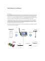
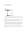
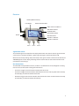
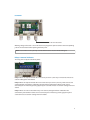
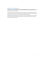
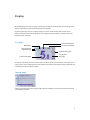
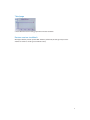
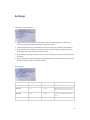
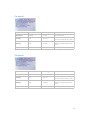
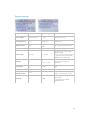
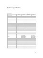
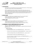
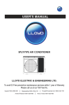
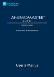
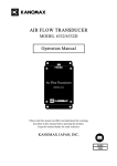
!SCARLET TECH
WL-410/XB
Wireless Wind Alarm
System
User Guide
Instrument at a Glance
Overview
3
3
Sensor & Receiver
Sensor
Receiver
Bluetooth (WL-410XB only)
4
4
5
7
Display
First page
Second page
Third page
Restore receiver to default
8
8
8
9
9
Settings
Setting of parameters
Max alarm
Pre alarm 2
Pre alarm 1
General settings
10
10
10
11
11
12
Technical Specification
Instrument
13
13
Safety, Handling, & Maintenance
Important safety information
Important handling information
Packing list
Accessories & spare parts
Standard
14
14
14
15
15
15
Warranty & Services
Warranty conditions
Services
16
16
16
2
Instrument at a Glance
Overview
WL-410/XB Wireless Wind Alarm System consists of a wind speed sensor and a receiver. The sensor
measures wind speed and transmit data to the receiver. The 3.5-inch LCD display of receiver shows
readings on the main page and the history graphs are shown in different pages. According to the
preset values, the receiver can trigger local alarms such as LED lights and buzzer, or trigger external
indication via 3 built-in relays when measured wind speeds exceeding the thresholds.
A 868 MHz radio frequency module is installed in the receiver of model WL-410 and WL-410XB. In
mode WL-410XB, an additional Bluetooth Low Energy chip is installed in the receiver to enable
smartphone communication functionality. WL-410XB sensor output power is stronger (+14 dBm)
than WL-410, allowing a longer transmission distance.
An optional 4-20 mA current loop module is available to both WL-410 and WL-410XB to make long
distance cable transmission possible.
Smartphone App
iOS/Android
Receiver
Bluetooth
Sensor
868 MHz RF
External
indicators
Relays
4-20 mA output
Control room
/ Equipment
3
Sensor & Receiver
Sensor
Wind cup
(replaceable)
Aluminum
sensor body
Battery cap
(O-ring sealed)
Sensor unit switches ON automatically when the anemometer cups revolve. It switches OFF 6 hours
after the anemometer cups stop revolving. In ON state, the sensor updates wind speed data every
two seconds.
Address
The correspondent sensor address has been preset at the factory. Always set the address correspond
to the address of the sensor from which the receiver will receive data. Address of the sensor is
indicated on the sensor label and in the interior of sensor battery compartment.
Range
Connection between sensor and receiver goes through free 868 MHz band (optionally 908MHz).
Transmission range is up to 500 meters (1300 meters at models XB) - at 10 m sensor mounting
height and when there is no obstacle between the sensor and the display unit. Inside buildings the
range is much shorter. Normally the signal can be received through two to three walls.
Power
When the “Lo battery” appears on the display, replace the sensor battery. Take off the battery cover
(on the bottom) by turning it anti clockwise. Pull out the battery holder and insert new battery
(Lithium 3.6 V AA).
4
Receiver
Antenna (SMA connector)
LCD display
Red LED for Max Alarm
Yellow LED for Pre Alarm 2
Max Alarm indicator
Up/Mute button
Down/History button
Buzzer
Set menu button
Pre Alarm 1 indicator
Pre Alarm 2 indicator
Port 1
Port 2
Port 3
Signals from sensor
The indication light on the top of the LCD display blinks when the receiver receives signals from the
sensor (every 2 seconds if reception is good). Signal strength is numerically shown in dB.
When the sensor stop sending data (in OFF state) or the signal is lost for a more than 30 seconds, the
“No data” appears on the display, indicating that the receiver doesn’t receive data from the sensor
(sensor OFF or out of range).
On-device alarms
The threshold wind speed of Pre Alarm 1, Pre Alarm 2 and Max Alarm can be configured via setting
menus. Please see the section “Settings” for more details.
•
Pre Alarm 1 triggers one LED indicator sit beside the LCD screen.
•
Pre Alarm 2 triggers two LED indicators sit beside the LCD screen and the yellow LED on the top
of LCD display. It sounds the buzzer interleaved.
•
Max Alarm triggers all three LED indicators sit beside the LCD screen and the red LED on the top
of LCD display. It sounds the buzzer continuously.
5
DC Power
12 to 24 V DC source
Working voltage of receiver is 12 to 24 V DC. Please plug the DC power source to the corresponding
jack on the circuit board after opening the front panel.
NOTE: Please make sure the polarity is correct otherwise the receiver will be damaged.
Relays & external indicators
The relay jacks are by the side of DC power.
Relay 3 When wind speed exceeds the value set on pre alarm 1, the relay 3 will activate. Please see
section “Settings” for more details.
Relay 2 When wind speed exceeds the value value set on pre alarm 2, the relay 2 will activate and
yellow light will start blinking and buzzer will sound with interruptions. When sound alarm is
activated you can mute it by pressing upper key for 3 seconds. Please see section “Settings” for more
details.
Relay 1 When set value is exceed the relay 1 will activate, red light will flash and buzzer will
continuously sound. When sound alarm is activated you can mute it by pressing upper key for 3
seconds. Please see section “Settings” for more details.
6
Bluetooth (WL-410XB only)
Wind speed / air temperature data are transmitted over Bluetooth every second. With free app
“Wind Smart” you can read data of current, average and maximum wind speed, temperature or view
history graphs on your smartphone.
In smartphone Application setting menu always set the address correspond to the address of the
WL-410/XB sensor. The range is up to 40 meters from WL-410/XB display unit. Inside the building the
range is much smaller. Range also varies with type of smartphone or tablet.
Android: Applications requires device with Android 4.3 or newer with Bluetooth Low Energy (BLE).
Apple: In iPad/iPhone settings for application Wind Smart configure parameter "Allow Location
Access" to "While Using the App".
7
Display
WL-410/XB display consists of 3 pages including: 1) readings of wind speed; 2) alarm settings and 3)
graphs to provide user information for project management.
By pressing HIST key user can navigate to page 2 and 3 to see the wind speed and max. alarm
history. To switch back to the first page user can long pressing HIST key for 3 seconds or leave the
device alone for 1 minutes.
First page
Max alarm threshold
Temperature
Wind speed unit
Signal strength
Current wind speed
Pre alarm 2 threshold
Peak wind bar graph
Current wind bar graph
The contents of display are shown above. Note: in both bar graphs, the max alarm value set by user is
always on the 3/4 bar height. One icon not shown in the photo is data packet receiving indicator and
it flashes by the side the signal strength.
Second page
8 hours peak wind speed history graph with 5 minutes resolution, each row presents the peak wind
speed during 5 minutes
8
Third page
8 hours Maximum alarm history graph with 5 minutes resolution.
Restore receiver to default
With upper button pressed at power ON – RESET is performed (all settings except “Sensor
Address”and “WS Cal. Factor” goes to default values).
9
Settings
Setting of parameters
1. Hold pressed SET key to enter the setting menu. If the password protection is active, enter
correct password. The options of settings are shown on display.
2. Select the option by using up and down keys and press SET key to enter into selected option.
3. By up and down keys select the parameter you wish to adjust and press SET key to enter into
selected parameter. The adjustable parameter blinks.
4. By up and down key adjust the parameter value. Press SET to enter new value and move to next
parameter.
5. Exiting setting menu: hold pressed SET key to move back for one level. Anemometer also return
to normal operation after 2 minutes of inactivity.
Max alarm
Factory default
Settable range
Description
Wind speed
72 km/h
1…50 m/s
Max alarm limit
On delay
0 sec
0…600 sec
Minimum time of exceed wind
speed to activate the max alarm
Off delay
0 min
0…60 min
Delay of alarm switch OFF after
wind speed drop below preset
level
Relay
Normal
Normal/interleaved
Inverted operation of relay
10
Pre alarm 2
Factory default
Settable range
Description
Wind speed
52 km/h
1…50 m/s
Pre alarm 2 limit
On delay
0 sec
0…600 sec
Minimum time of exceed wind
speed to activate the pre alarm 2
Off delay
0 min
0…60 min
Delay of alarm switch OFF after
wind speed drop below preset
level
Relay
Normal
Normal/interleaved
Inverted operation of relay
Factory default
Settable range
Description
Wind speed
42 km/h
1…50 m/s
Pre alarm 1 limit
On delay
0 sec
0…600 sec
Minimum time of exceed wind
speed to activate the pre alarm 1
Off delay
0 min
0…60 min
Delay of alarm switch OFF after
wind speed drop below preset
level
Relay
Normal
Normal/interleaved
Inverted operation of relay
Pre alarm 1
11
General settings
Factory default
Settable range
Description
Sensor address
Enclosed sensor
1…255
Set the sensor address of your
Wind speed sensor
Averaging period
2 sec
2/10/30 sec
Averaging period for showed
wind speed
Wind speed unit
km/h
m/s, km/h, mph,
knots
Unit of displaying wind speed
Temperature unit
°C
° C or ° F
Unit of displaying Temperature
20 mA output
180 km/h
10…50 m/s
Wind speed at 20 mA output
4mA = 0 km/h
20 mA = seted value wind speed
* applicable only at model with
additional 4-20 mA output
Password
No
No
Yes:0000…9999
Activation of password
protection and setting of
password
Sound alarm
On
On/Off
Switching sound alarm ON and
OFF
Language
English
English/French
Language selection
Wind speed
calibration factor
+0.0%
Calibration factor for wind speed
(-15,0 ...+15,0% in 0,5% steps)
On
Power ON/OFF Bluetooth
transmitter
* applicable only at WSM
W410XB model
Bluetooth
On/Off
12
Technical Specification
Instrument
WL-410/
4-20mA
WL-410
WL-410XB/
4-20mA
WL-410XB
Sensor & receiver
0.6…50.0 m/s
Measurement range
m/s, km/h, knots, mph
Unit
0.1 m/s
Resolution
+/-3%
Accuracy
Averaging period
Selectable 2 s, 10 s, 30 s
Operating voltage
12…24 V DC
300 mA (max.)
Power consumption
Transmission distance
Distance with YAGI antenna
300 m
1300 m
1.5…2.4 km
6.5…10.0 km
1 A/12 V DC; 1 A/24 V DC
Relay contact rating
-25…60° C
Temperature operating range
3.6 V AA Lithium batteries
Sensor battery
5 years
Sensor battery life
3 years
85…90 dB
Audible alarm
50 ohm, SMA connector
Antenna input (receiver)
Output
3 x relays, 2 A / 24 V
Relay
Output
-
4…20 mA
4 mA=0 m/s
20 mA=10…50 m/s
(programmable)
-
4…20 mA
4 mA=0 m/s
20 mA=10…50 m/s
(programmable)
Mechanical
Bearings
2 x precision stainless steel ball bearing
AL/PVC
Sensor housing
Sensor cups (replaceable)
PA (Nylon)
Receiver housing
ABS, IP65
Sensor dimension
Height 210 mm, cup-to-cup diameter 120 mm
150 x 80 x 55 mm
Receiver dimension
Mounting
Bluetooth LE
Mounts on a pipe with ø20 mm outside diameter
-
Yes. Range is up to 30 m.
13
Safety, Handling, & Maintenance
Important safety information
WARNING: Failure to follow these safety instructions could result in fire, electric shock, or other
injuries, or damage to sound level meter or other property. Read all the safety information below
before using sound level meter.
Operate Avoid using instrument in humid or wet places. Make sure that humidity is within the limits
indicated in the next section. Avoid using meter in presence of explosive gas, combustible gas,
steam or excessive dust.. Be sure to turn it off after use. If you expect not to use the instrument for a
long period remove batteries to avoid leakages of battery liquid which could damage the its inner
components.
Handling Handle the meter with care. It is made of sensitive electronic components. The meter can
be damaged if dropped, burned, punctured, or crushed, or if it comes in contact with liquid. Don’t
use a damaged meter, such as one with a cracked screen, as it may cause injury.
Important handling information
Cleaning Clean instrument immediately if it comes in contact with anything that may cause stains—
such as dirt, ink, makeup, or lotions. To clean:
•
Disconnect all cables and turn instrument off.
•
Use a soft, lint-free cloth.
•
Avoid getting moisture in openings.
•
Don’t use cleaning products or compressed air.
Operating temperature The instrument is designed to work in ambient temperatures between 5°
and 40° C (41° and 104° F) and stored in temperatures between -10° and 60° C (14° and 140° F). The
instrument can be damaged and battery life shortened if stored or operated outside of these
temperature ranges. Avoid exposing the instrument to direct sunlight even the the air temperature
is within the limits.
Operating humidity The instrument is designed to work in humidity < 80%rh and stored in dry
place where humidity is less than 70%rh.
Store microphone carefully Microphone is the key component of the instrument and keep it dry
and avoid severe shake or vibration.
14
Battery replacement Low battery icon displayed in LCD indicates the user needs to replace batteries
on sensor. To replace:
•
Unscrew the O-ring sealed battery cap anti-clockwise.
•
Pull out the battery holder, remove old battery and insert new one.
•
Insert the battery cap back and screw the O-ring sealed battery cap.
NOTE: Please make sure screw the O-ring sealed cap correctly to have the best dust and water
proof capability.
Packing list
• Wind speed sensor x 1
• Receiver unit x 1
• SMA antenna x 1
• User guide x 1
• Bluetooth & 4-20 mA current loop modules are optional in WL-410XB
Accessories & spare parts
To help in mounting and to enhance the transmission distance, you may need the following
accessories. Please contact your local representative to get the quotation.
Accessories
•
Magnetic mounting assembly (receiver)
•
YAGI antenna with 3 m cable
•
Outdoor antenna with 3 m cable
•
Self-leveling mounting assembly (sensor)
•
Magnetic mounting assembly (sensor)
Spare parts
Wind cup is replaceable and can be order separately.
Standard
EMC This instrument was designed in accordance with EMC Standards in force and its compatibility
has been tested in accordance with EN61326-2 (2006).
15
Warranty & Services
Warranty conditions
This instrument is guaranteed for one year against material or production defects, in accordance
with our general sales conditions. During the warranty period the manufacturer reserves the right to
decide either to repair or replace the product.
Should you need for any reason to return back the instrument for repair or replacement take prior
agreements with the local distributor from whom you bought it. Do not forget to enclose a report
describing the reasons for returning (detected fault). Use only original packaging. Any damage
occurred in transit due to non-original packaging will be charged anyhow to the customer.
The warranty doesn’t apply to:
Accessories and batteries (not covered by warranty)
Repairs made necessary by improper use (including adaptation to particular applications not
foreseen in the instructions manual) or improper combination with incompatible accessories or
equipment.
Repairs made necessary by improper shipping material causing damages in transit.
Repairs made necessary by previous attempts for repair carried out by non-skilled or unauthorized
personnel.
Instruments for whatever reason modified by the customer himself without explicit authorization of
our Technical Dept.
The contents of this manual may not be reproduced in any form whatsoever without the
manufacturer’s authorization.
Our products are patented. The logotypes are registered. We reserve the right to modify
characteristics and prices as part of technological developments which might require them.
Services
Shouldn’t the instrument work properly, before contacting your distributor make sure that batteries
are correctly installed and working, check the test leads and replace them if necessary.
16
Scarlet Tech Co., Ltd.
© 2015 Scarlet Tech Co., Ltd. All rights reserved.
4F-3, No. 347 , HePing E Rd, 2nd Sec,
DaAn District, Taipei City 106, Taiwan
E-mail: [email protected]
http://www.scarlet.com.tw