1
USER MANUAL
WEIGHT INDICATOR
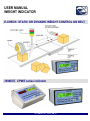
E-CHECK: STATIC OR DYNAMIC WEIGHT CONTROL ON BELT
3590EXT, CPWE series indicator
E-CHECK_03_12.05_EN_U
3590EXT, CPWE series indicators
E-CHECK_03 _12.05_EN_U
INDEX
1. INTRODUCTION ................................................................................................................................................................. 4
2. MAIN TECHNICAL SPECIFICATIONS ............................................................................................................................... 5
2.1 EXTRA ACCESSORIES............................................................................................................................................... 6
2.2 SYMBOLS .................................................................................................................................................................... 6
3. INSTALLATION .................................................................................................................................................................. 7
3.1 DRILLING TEMPLATE, CASE AND DIMENSION........................................................................................................ 7
3.2 POWER SUPPLY & START-UP .................................................................................................................................. 8
3.3 CONNECTION TO THE BATTERY POWERED PRINTER .......................................................................................... 9
4. FUNCTION PANEL KEYS .................................................................................................................................................. 9
4.1 "2ndF" KEY: SECOND FUNCTION OF THE KEYS ................................................................................................... 10
4.2 ENTERING ALPHANUMERIC TEXT ......................................................................................................................... 11
4.3 DISABLING THE KEYBOARD ................................................................................................................................... 11
4.4 HELP MENU .............................................................................................................................................................. 11
4.5 INDICATOR CONNECTED TO PC KEYBOARD ....................................................................................................... 12
4.5.1 DIRECT COMPILATION OF INPUT TEXT ...................................................................................................... 12
4.6 REMOTE CONTROL.................................................................................................................................................. 12
4.6.1 RADIO REMOTE CONTROL TO ASSOCIATE ............................................................................................... 13
4.6.2 RADIO REMOTE CONTROL........................................................................................................................... 13
5. DISPLAY FUNCTIONS ..................................................................................................................................................... 14
5.1 WEIGHT ZOOM ......................................................................................................................................................... 15
5.2 STATUS INDICATORS .............................................................................................................................................. 15
5.2.1 BATTERY LEVEL INDICATION ...................................................................................................................... 16
5.3 MODIFICATION OF THE DISPLAYED DATA ............................................................................................................ 16
5.3.1 SYSTEM STATUS VISUALISATION ............................................................................................................... 20
5.4 MESSAGES ............................................................................................................................................................... 21
6. SCALE ZERO FUNCTION ................................................................................................................................................ 23
7. TARE FUNCTIONS ........................................................................................................................................................... 23
7.1 SEMIAUTOMATIC TARE ........................................................................................................................................... 23
7.2 PRESET TARE .......................................................................................................................................................... 23
7.3 CALCULATED MANUAL TARE ................................................................................................................................. 23
7.4 TARE CANCELLATION ............................................................................................................................................. 23
7.5 LOCKED/UNLOCKED TARE ..................................................................................................................................... 23
7.6 LIMITATION OF THE TARE FUNCTIONS ................................................................................................................. 24
7.7 LINKING A KNOWN TARE VALUE TO AN ARTICLE ................................................................................................ 24
8. MULTIRANGE FUNCTION ............................................................................................................................................... 24
9. DISPLAY OF METRIC DATA (inFO) ................................................................................................................................ 24
10. FILLING IN THE INPUT TEXT ........................................................................................................................................ 26
11. ARTICLES DATABASE .................................................................................................................................................. 27
11.1 ENTRY ..................................................................................................................................................................... 27
11.2 MODIFICATION ....................................................................................................................................................... 28
11.3 CANCELLATION ...................................................................................................................................................... 28
11.4 PRINTING ................................................................................................................................................................ 28
11.5 SELECTION/UNSELECTION ................................................................................................................................... 28
11.6 ENTRY, MODIFICATION AND QUICK SELECTION OF ARTICLE 000 .................................................................. 28
11.7 HELP ........................................................................................................................................................................ 28
12. DATABASE ACCESS PASSWORD ............................................................................................................................... 29
13. WEIGHING PROCEDURES ............................................................................................................................................ 29
13.1 SYSTEM STATUS CONTROL ................................................................................................................................. 29
13.2 ENABLING / DISABLING THE WEIGHING CYCLE ................................................................................................. 29
13.3 DESCRIPTION OF THE CYCLE PHASES .............................................................................................................. 30
13.3.1 WEIGHT ACQUISITION ................................................................................................................................ 30
13.3.1.1 AT HALT WITH 1 PHOTO CELL ................................................................................................... 30
13.3.1.2 IN MOTION WITH 1 PHOTO CELL ............................................................................................... 31
13.3.1.3 IN MOTION WITH 2 PHOTO CELLS ............................................................................................. 31
13.3.1.4 AT HALT WITHOUT PHOTO CELLS ............................................................................................ 32
2
3590EXT, CPWE series indicators
E-CHECK_03 _12.05_EN_U
13.3.1.5 IN MOTION WITH NO PHOTO CELL ............................................................................................ 33
13.3.2 TOLERANCE CHECK ................................................................................................................................... 34
13.3.2.1 CHECKING WITH ARTICLE AND T1,T2,T3 TOLERANCE SETTING........................................... 35
13.3.2.2 CHECKING WITH ARTICLE AND MINIMUM AND MAXIMUM THRESHOLD SETTING .............. 35
13.3.2.3 CHECKING WITHOUT ARTICLE AND FAST MINIMUM AND MAXIMUM THRESHOLDS
SETTING ..................................................................................................................................................... 36
13.3.2.4 DETERMINATION OF TOLERANCE RANGE ............................................................................... 36
13.3.2.5 CHECKING QUANTITIES IN ml .................................................................................................... 37
13.3.2.6 AUTOMATIC TARGET RECALCULATION AFTER N WEIGHS WITHIN TOLERANCE ............... 37
13.3.3 CORRECTION OF THE OUT OF TOLERANCE WEIGHT ............................................................................ 37
13.3.4 TOTALIZATION ............................................................................................................................................. 38
13.3.4.1 TOTALIZATION OF ONLY THE WEIGHS WITHIN TOLERANCE ................................................ 38
13.3.4.2 VISUALISATION AND CLEARING OF THE ACCUMULATED TOTALS ....................................... 38
13.3.4.3 CLEARING AND AUTOMATIC PRINTING OF THE PARTIAL TOTAL AFTER N WEIGHS .......... 39
13.3.4.4 ADDITIONAL VALUE..................................................................................................................... 39
13.3.4.5 TICKET PROGRESSIVE ............................................................................................................... 39
13.3.5 WEIGH RESULT INDICATION AND ENABLING OF THE LINKED OUTPUTS ............................................ 40
13.3.6 STOP AND RESTART OF THE BELTS ........................................................................................................ 41
13.3.6.1 STOP OF BELTS FOR WEIGH OUT OF TOLERANCE / MANUAL EXPULSION ......................... 41
13.3.6.2 STOP OF BELTS AFTER EVERY WEIGH .................................................................................... 42
13.3.6.3 STOP OF BELTS AFTER A NUMBER OF WEIGHS OUT OF TOLERANCE ................................ 42
13.3.7 EVACUATION AND AUTOMATIC EXPULSION ........................................................................................... 42
13.3.8 WEIGHING BELT AUTOZERO ..................................................................................................................... 42
13.4 CYCLE LOCK AND INTERRUPTION OF THE WEIGH (NON WEIGHED PACK) ................................................... 43
13.4.1 DOWNSTREAM BLOCK ............................................................................................................................... 44
13.4.2 EMERGENCY / MOTOR LOCK..................................................................................................................... 44
13.4.3 UNDERLOAD / OVERLOAD WEIGHT LOCK ............................................................................................... 44
13.5 CYCLE RESTORAL AFTER POWER OUTAGE ...................................................................................................... 44
13.6 MANAGEMENT OF CADENCE PHOTOCELL AND BELT ...................................................................................... 45
13.7 ALARM OUTPUT MANAGEMENT ........................................................................................................................... 45
14. PRINTOUTS .................................................................................................................................................................... 45
14.1 LINKING OF THE FORMATS TO THE PRINT FUNCTIONS ................................................................................... 47
14.1.1 QUICK LINKING OF THE FORMATS ........................................................................................................... 48
14.2 LOT WEIGHS REPORT ........................................................................................................................................... 48
14.2.1 PRINTING OF THE HEADING ...................................................................................................................... 48
14.2.2 TOTALIZATION ............................................................................................................................................. 49
14.2.3 TOTAL LOT ................................................................................................................................................... 49
14.3 REPETITION OF THE LAST EXECUTED PRINTOUT ............................................................................................ 49
14.4 STANDARD PRINTING FORMATS ......................................................................................................................... 49
15. OTHER FUNCTIONS ...................................................................................................................................................... 52
15.1 DIAGNOSTIC PERIPHERALS ................................................................................................................................. 52
15.2 COM DATA DIAGNOSTIC ....................................................................................................................................... 52
15.3 CALCULATOR ......................................................................................................................................................... 53
15.3.1 HELP ............................................................................................................................................................. 53
15.4 DISPLAY OF NET WEIGHT WITH SENSITIVITY X 10 (for testing use during calibration) ...................................... 53
15.5 SETTING DATE / TIME ............................................................................................................................................ 53
16. FUNCTIONING WITH ALIBI MEMORY .......................................................................................................................... 54
16.1 READING OF THE WEIGHS CARRIED OUT .......................................................................................................... 54
16.2 SERIAL COMMANDS FOR MANAGING THE ALIBI MEMORY:.............................................................................. 55
16.2.1 REQUEST WEIGHT VALUE WITH WEIGH ID .............................................................................................. 55
16.2.2 STRING FORMAT (WEIGHT/ID) ................................................................................................................... 56
16.2.3 WEIGH READING ......................................................................................................................................... 57
16.2.4 ALIBI MEMORY CANCELLATION (only with non approved instrument) ....................................................... 57
DECLARATION OF CONFORMITY ..................................................................................................................................... 58
WARRANTY ......................................................................................................................................................................... 58
3
3590EXT, CPWE series indicators
E-CHECK_03 _12.05_EN_U
1. INTRODUCTION
This manual was created to help you install and learn all about the functional possibilities of the purchased indicator.
Besides having the standard features of a high precision scale, the instrument manages static and dynamic weighing on
belts.
The Input/Output board allows the instrument to control various external devices, receive external commands, and to
communicate with a personal computer or to be inserted in a network of weight indicators controlled by a PC.
WARNING
This instrument is covered by a warranty and MUST NOT BE OPENED BY THE USER for any reason whatsoever. Any
attempt to repair or modify the unit could expose the user to a risk of electric shock and will void the entire warranty.
Any problem with the unit or with the system must be communicated to the manufacturer or to the dealer where it was
purchased.
In any case, DISCONNECT THE POWER SUPPLY before taking any action.
Do not pour liquids on the weight indicator.
Do not use solvents to clean the weight indicator.
Do not expose the instrument to direct sunlight nor place it near heat sources.
Place the weight indicator and the platform on a non vibrating base.
READ SECTION “INSTALLATION” CAREFULLY AND IMPLEMENT THE INFORMATION FOUND THERE
Do not install in any area where a risk of explosion exists
The crossed-out wheeled bin on the product means that at the product end of life, it must be taken to
separate collection or to the reseller when a new equivalent type of equipment is purchased. The
adequate differentiated refuse collection in having the product recycled, helps to avoid possible
negative effects on the environment and health and supports the recycling of the materials of which the
equipment is made. The unlawful disposal of the product by the user will entail fines foreseen by the
current regulations.
NOTE FOR THE USER
Please take note that when ―TECH.MAN.REF.‖ is mentioned, this refers to the Technical manual which may be obtained
from the reseller.
4
3590EXT, CPWE series indicators
E-CHECK_03 _12.05_EN_U
2. MAIN TECHNICAL SPECIFICATIONS
POWER SUPPLY
- 8 ÷ 40 Vdc
- 6 Vdc from external rechargeable battery (optional).
MAXIMUM POWER
OPERATING TEMPERATURE
CONVERTER
CONVERSION SPEED
INPUT SIGNAL RANGE
MINIMUM VOLTAGE PER DIVISION
AUTOMATIC ZERO TRACKING
16 VA.
From -10 to +40 °C.
24-bit Sigma Delta.
Up to 400 conv./sec with automatic selection.
0,6 mV/V - 3,2 mV/V.
0.3 V (approved instrument); 0.03 V (non-approved instrument).
Only in gross mode, programmable at +/- ¼, ½, 1, 2 divisions.
ZERO RANGE
AUTOMATIC ZERO AT START-UP
LOAD CELL POWER SUPPLY
LOAD CELL CONNECTION
DISPLAY DIVISIONS
Configurable up to +/- 50% of max load capacity.
Configurable up to +/- 50% of max capacity.
5Vdc ± 5%, 120mA (up to 8 350-Ohm cells).
6 wires with Remote Sense.
10.000 legal, expandable up to 800.000 for internal use (with signal coming
from a cell of at least 1,6mV/V).
Back lit graphic 160x32 dot LCD
Subtractive possible on the entire capacity.
Database of 1000 articles and 20 free texts.
Graphic icons on LCD display.
Impermeable polycarbonate keyboard (IP65 protection degree),with
membrane keys having an audible and tactile feedback.
Fully digital calibration and linearization (up to 8 points) programmable from
keyboard or from PC with Dinitools ™.
Fitted, with buffered RAM.
Anodized aluminium case
DISPLAY
TARE FUNCTION
MEMORY/DATABASE
INDICATIONS
KEYBOARD
PARAMETER SET-UP
TIME/DATE
CASE
SERIAL OUTPUTS
- 2 input/output RS232 ports on terminal board/ amp connector.
- 1 input/output RS485 port on terminal board or RS232 on amp connector.
INPUTS AND OUTPUTS
- 8 inputs (optoisolated photo couplers), 12Vdc – 24Vdc, 20mA max.
- 16 outputs (optoisolated photomosfets), 48Vac / 0.15A, 60Vdc / 0.15A.
- Management of the PC keyboard, bar code reader.
ANALOGUE OUTPUT (OPTIONAL)
16 BIT, settable on the net or gross weight on a fixed value for each article
(belt speed management); the maximum resistance applicable on the output
current is 350 ohm and the minimum resistance applicable on the output
voltage is 10 kohm.
5
3590EXT, CPWE series indicators
E-CHECK_03 _12.05_EN_U
2.1 EXTRA ACCESSORIES
The indicator can be implemented with additional internal and external modules used to increase interfacing possibilities.
For example, one can increase the number of usable outputs; one may connect various types of printers (in order to have a
report of the weighs made) or one can connect a giant display in order to better see the weigh operations. Also, one can
connect a PC temporarily in order to simply program the instrument through Dinitools™, or permanently in order to have a
complete management of the weighs.
Contact the reseller for the list of the available hardware and software accessories.
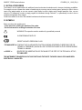
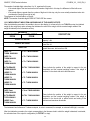
2.2 SYMBOLS
Below are shown the symbols used:
- In the manual for recalling the attention of the reader
- On the instrument for recalling the attention of the user
WARNING! This operation must be carried out by specialized personnel
IN CONFORMANCE WITH CE
IDENTIFYING WITH PRECISION CLASS
“TECH.MAN.REF.” IT MEANS THAT AN ADVANCED FUNCTION IS BEING DESCRIBED (THEREFORE FOR THE
TECHNICAL PERSONNEL) WHICH WILL BE FURTHER EXPLAINED IN THE CORRESPONDING
TECHNICAL MANUAL.
<< XXXXX >>
IDENTIFIES THE ABBREVIATION OR THE NAME OF THE STEP OF THE TECHNICAL SET-UP,
TECH.MAN.REF.
THE INSTRUMENT’S DANGEROUS VOLTAGE PARTS AND THE PARTS THE USER CAN ACCESS HAVE BEEN
ELECTRICALLY INSULATED.
6
3590EXT, CPWE series indicators
E-CHECK_03 _12.05_EN_U
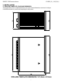
3. INSTALLATION
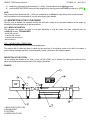
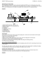
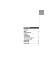
3.1 DRILLING TEMPLATE, CASE AND DIMENSION
The weight indicator has an anodized aluminium case, whose external dimensions are shown in the figure.
It should be mounted on a panel board respecting the safety norms.
DRILLING TEMPLATE DIMENSION: 187,5mm x 91,5mm
7
3590EXT, CPWE series indicators
E-CHECK_03 _12.05_EN_U
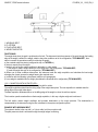
3.2 POWER SUPPLY & START-UP
The indicator is powered with 8÷40 Vdc voltage or a 6 Vdc optional battery. For the connection to the power supply mains the
safety norms must be respected including the use of a ―clean‖ line without noise and interference caused by other electronic
devices.
NOTE: It is advisable to completely recharge it (12 hours) in the first installation of the instrument; we
RECOMMEND disconnecting the battery if the instrument is not going to be used for more than 30 days.
Rechargeable battery version: the external optional battery lasts about 15 hours (without expansion board, with a 1-cell
platform) and a recharge time of about 12 hours.
BATTERY FEATURES
Material
LEAD
Power
4,5 Ah
Voltage
6V
THE BATTERY MUST BE SUPPLIED DIRECTLY FROM THE MANUFACTURER.
Do not connect other equipment to the same socket as the one that the adapter is in.
Do not step on or crush the power supply cable
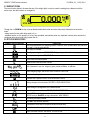
TO TURN ON:
The instrument is automatically turned on as soon as it is powered.
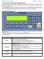
The LCD display shows:
- initially a welcome message (settable in the TECHNICAL SET-UP, << LOGO >> step, TECH.MAN.REF.) while the
instrument carries out a series of checking and preheating self tests.
- CHECK - XX
name of the installed software, in which XX identifies the software language.
XX.YY
is the software version installed.
- ―EXECUTION AUTOZERO‖; the instrument carries out the "autozero at start-up‖ function: if a weight is detected within
the percentile set in the << Auto 0 >> step (TECH.MAN.REF.), it is cleared; if the weight is not within this tolerance:
- with a non approved instrument, the display shows the weight after a few instants,
- with an approved instrument, the message ―EXECUTION AUTOZERO‖ appears continuously on the
display, until the weight is within tolerance.
NOTES:
- The autozero function at start-up can be disabled in the set-up environment (only with a non approved instrument), see
the <<Auto 0>> parameter.
- If the start-up follows an eventual missing voltage of the indicator with an object to be weighed on the weighing belt, the
instrument carries out the auto zero only after the system is restored, as described in section ―CYCLE RESTORAL AFTER
POWER OUTAGE‖ .
By pressing the 2ndF key while the version is shown in the display, the indicator shows in sequence:
XX.YY
in which XX indicates the instrument type, YY indicates the metrological software version.
CHECKSUM = XXXX in which XXXX is the checksum of the libraries of the weight management.
XX.YY.ZZ
is the installed software version.
HH
is the installed hardware version (08).
LEGAL FOR TRADE
or HIGH RESOLUTION
if the instrument is APPROVED or UNAPPROVED, respectively.
9.XXXXX
is the the g gravity value (only with APPROVED instrument).
TURNING OFF THE INSTRUMENT
Remove the instrument‘s power supply.
NOTE: it isn‘t possible to put the instrument in standby. By pressing at length the C key, the instrument is restarted.
8
3590EXT, CPWE series indicators
E-CHECK_03 _12.05_EN_U
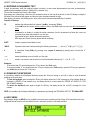
3.3 CONNECTION TO THE BATTERY POWERED PRINTER
In a system where the indicator is connected to a printer, both are battery powered, the printer is normally maintained in
STAND-BY and powered only when a printout is needed. This function reduces the energy absorbed by the battery when
the printer is not being used.
If, in this configuration, one should power the printer to change the paper and other maintenance jobs, one needs to keep
pressed the ENTER and 0 keys (with the weighing cycle disabled, see section ―ENABLING / DISABLING THE WEIGHING
CYCLE‖): the display shows Prn - on, and the printer is kept on. Press any key to exit from this condition.
4. FUNCTION PANEL KEYS
In the following section, and later on in the manual, the keys‘ functioning is described in accordance to how these are
configured by factory.
It is possible to customise the functionality of the keys through the << F.Keys >> step.
Where it isn‘t specified, the function is carried out with the weighing cycle disabled (see section ―ENABLING / DISABLING
THE WEIGHING CYCLE‖).
KEY
C / DEL
TARE/ ZERO
Fn / ENTER
2nd F
FUNCTION
If pressed for an instant, it clears the tare value.
If pressed at length it restarts the instrument.
Exits the parameter without confirming and saving the modifications.
In the numeric input phase, it quickly clears the present value.
Causes the display of the present metric scale information (see section “DISPLAY OF
METRIC DATA (inFO)‖).
- If pressed for an instant it carries out the semiautomatic tare, or cancels the value of tare if
the gross weight is 0.
- If pressed at length, it executes the zero functions:
a) With the weighing cycle disabled, it clears the displayed gross weight, if it‘s within the
percentage configured in the << 0.PErC >> step.
b) During the weighing cycle, it enables the auto zero of the belt (see section ―WEIGHING
BELT AUTOZERO‖).
-
- In the alphanumeric input phase, it confirms the entry made.
- In the menu it allows to enter a step or to confirm a parameter inside a step.
- If pressed together with the other keys, it allows carrying out a specific function. (see
section ―"2ndF" KEY: SECOND FUNCTION OF THE KEYS‖ ).
9
3590EXT, CPWE series indicators
E-CHECK_03 _12.05_EN_U
- In the numeric or alphanumeric input phase, it enters, in this order, the following
characters: . , ; : # < > \ | ” % & / ( ) = ? ^ ’ [ ] { };
- HELP function, see section ―HELP MENU‖.
. / HELP
- If pressed for an instant, it enters into the article database.
- If pressed at length, it locks and unlocks the instrument‘s keyboard (except the C key).
F1
- If pressed for an instant, it allows to enter the minimum threshold, in the threshold check
(see section ―TOLERANCE CHECK‖).
- If pressed at length, the weight visualisation function with sensitivity x 10 is enabled
- If pressed for an instant, it allows to enter the maximum threshold, in the threshold check
(see section ―TOLERANCE CHECK‖).
- If pressed at length, one can adjust the date and time of the instrument.
- If pressed for an instant, it allows to fill in the free texts, if configured
- If pressed at length, it enters the instrument‘s diagnostics menu.
- With the weighing cycle disabled, it commands the data transmission to the printer serial
port.
- If pressed at length, it locks/unlocks the tare.
- It allows scrolling ahead inside the menu steps or in the parameters within a step.
- In the numeric or alphanumeric phase, it decreases the blinking digit.
- It allows scrolling backwards in the menu steps or in the parameters within a step.
- In the numeric or alphanumeric input phase, it increments the blinking digit.
- If pressed for an instant, it executes the printing and the zeroing of the partial total.
- In the numeric or alphanumeric input phase, it selects the digit to be modified from right to
left.
- If pressed for an instant, it executes the printing and the zeroing of the general total.
- In the numeric or alphanumeric input phase, it selects the digit to be modified from left to
right.
- If pressed for an instant, it executes the printing and the zeroing of the large total.
- In the numeric or alphanumeric input phase, introduces a space between two characters.
- Entry of digits or characters.
- While weighing, these enter a numeric value with which it‘s possible to:
1) Set the tare value, by pressing subsequently the TARE key (see section ―PRESET
TARE‖).
2) It executes calculations, and sums or subtractions the result from the current tare (see
section ―CALCULATOR‖).
F2
F3
F4
F5
F6
F7
F8
F9
F10
NUMERIC
KEYBOARD
4.1 "2ndF" KEY: SECOND FUNCTION OF THE KEYS
In the weighing phase, by pressing the 2ndF key together with another key, it‘s possible to execute various functions
(continue reading the manual for the details of the functions):
2ndF
F1
Print/Clearing of Total of each handled Article
2ndF
F3
Prints weighs‘ report
2ndF
F5
Repetition of the last printout made.
2ndF
F8
Net/Gross Conversion
2ndF
F9
Modification of the data shown on the display with non active weight zoom
10
3590EXT, CPWE series indicators
E-CHECK_03 _12.05_EN_U
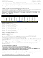
4.2 ENTERING ALPHANUMERIC TEXT
It might be necessary, while the weighing system is working, to enter some alphanumerical texts such as descriptions,
alphanumerical messages (operator, number of lot, customer, etc.).
To enter the characters one uses the 0 to 9 keys.
By pressing one of these keys a few times, the characters shown on the key will be shown on the LCD display: initially the
first letter in the bottom left will appear, and then the other characters towards the right.
After digiting a character, the blinking cursor, after a few instants, advances automatically of a position.
Function of the keys
F5
switches the writing mode from ―numeric‖ (nuM) to ―characters‖ (ChAr).
In the nuM mode one enters just the numbers, while in the ChAr mode one can enter all the characters of
a key.
C
If pressed for an instant, it cancels the written characters: first the characters that follow the cursor are
cancelled; than those that precede it, one at a time.
If pressed at length, it deletes all entered characters.
With empty text, it exits the entry phase without confirming.
SHIFT
It enters a space in the middle of a text.
./HELP
If pressed a few times it allows entering the following characters: . , ; : # < > \ | ” % & / ( ) = ? ^ ’ [ ] { }
0
in ―characters‖ mode (ChAr), by pressing once a space is entered; by pressing twice it enters the ―0‖
character;
moves the blinking cursor to the left or to the right.
scrolls in one sense or the other the list of all the enterable characters (0, 1…9, A, B…Y, Z).
Examples:
- To enter the letter ―B‖ one should press the ―2‖ key twice in the ChAr mode.
- To enter the number ―3‖ one should press the ―3‖ key four times (in the ChAr mode) or press the F5 key (one passes to
the nuM mode) and press the ―3‖ key once.
4.3 DISABLING THE KEYBOARD
It is possible to disable the all keyboard functions (except the C key for turning on and off), in order to avoid undesired
pressings of the scale keys:
- To lock the keyboard, press at length the F1 key: the display shows the ―LoCK‖ message for a few instants. Now the
keyboard is LOCKED: if one presses a key, the display shows for a few instants the ―PRESS AT LENGTH F1 FOR
UNLOCKING‖ message.
- To unlock the keyboard, press again at length, the F1 key: the display shows the ―unLoCk‖ message for a few
instants.
NOTE: It‘s possible to lock all keys individually in a permanent way through the TECHNICAL SET-UP, TECH.MAN.REF..
4.4 HELP MENU
By pressing at length the HELP key it is possible to access a menu containing the list of keys of the instrument and of any
configured remote controls, with the relative function, and status (locked or unlocked) indication.
11
3590EXT, CPWE series indicators
E-CHECK_03 _12.05_EN_U
The display shows:
- in the upper part: the key, followed by the code of the linked function in the << F.Keys >> step, and a symbol
indicating whether the key is unlocked (
) or locked (
) in the << EN.KEYS >> step;
- in the lower part: the description of the linked function.
Scroll the list with the arrow keys , press the C key to exit.
4.5 INDICATOR CONNECTED TO PC KEYBOARD
It‘s possible to connect a PC keyboard (optional), used to emulate the functions of the keys of the indicator.
The keys are managed in the following way:
Esc
and Canc
Enter
Numeric and
alphanumeric
keys, SHIFT
and CAPS
LOCK
Cursor keys
Cursor keys
F1, F2….F10
F11
F12
- C key.
- If pressed at start-up, it allows entering in the technical set-up.
- In the alphanumeric input, it deletes all entered characters.
-C key.
- If pressed at start-up, it allows entering in the technical set-up.
- In the alphanumeric input, it cancels first the characters which follow the cursor, then the ones which
precede it, one at a time.
- Fn key.
- Confirms the entered value.
- Enters the displayed step
- Quick entry of a numeric and alphanumeric string: through the CAPS/LOCK or SHIFT key it is possible to
switch from the capital letters to the lower case letters, and vice versa, or enter the second character
corresponding to the key (for example ", %, &, /, ? ).
- Scroll the parameters.
- Increase or decrease the blinking digit while entering a value.
- When entering a value or an alphanumeric string, it scrolls the digits to the right or to the left.
F1,F2….F10 keys.
2ndF key.
TARE key.
NOTE: through the remote keyboard, it‘s not possible to carry out the functions made by pressing the keys at length.
4.5.1 DIRECT COMPILATION OF INPUT TEXT
By entering an alphanumeric text through an external keyboard the instrument goes in alphanumeric clipboard mode; by
pressing a function key from F1 to F9 programmed with a direct function to compile an input text (121 up to 130) the edited
alphanumeric text is assigned to the corresponding input text.
Alphanumeric clipboard contains up to 32 characters.
4.6 REMOTE CONTROL
The remote control allows to remote the functionality of the keys of the instrument. The instrument manages the radio
remote control with 6 keys in two modes: remote control to be associated to the instrument and remote control working
without any procedure of association.
By pressing on the remote control a key associated to a keyboard key, it‘s possible to repeat the short pressure and the
pressure at length.
12
3590EXT, CPWE series indicators
E-CHECK_03 _12.05_EN_U
4.6.1 RADIO REMOTE CONTROL TO ASSOCIATE
The remote control works only if it is associated to the instrument.
To enable this functioning it‘s necessary to set ―RD 6‖ in the SETUP >> inF.rEd step; then in the steps KEY 1…KEY 6 it‘s
possible to associate the functions to the keys of the remote control (TECH.MAN.REF.).
The procedure to associate the remote control is the follow:
- press the first two keys of the remote control for three seconds;
- press ENTER by keyboard when the message is displayed;
- now the remote control is associated to the instrument.
When the remote control is associated, the keys work according to the settings of the steps KEY 1…KEY 6.
It‘s possible to delete the associating of the remote control with the follow procedure:
- press the first two keys of the remote control for three seconds;
- press C key by keyboard when the message is displayed;
- now the remote control is not associated to the instrument.
NOTE:
The maximum number of remote controls that can be associated to the instrument is 3. If 3 remote controls have already
associated to the instrument and if you want to associate another, the instrument delete the first associating and save the
new associating.
4.6.2 RADIO REMOTE CONTROL
The remote control works when the instrument is started. In this mode it‘s not necessary to associate the remote control to
the instrument.
To enable this functioning it‘s necessary to set ―RD.BR 6‖ in the SETUP >> inF.rEd step; then in the steps KEY 1…KEY 6
it‘s possible to associate the functions to the keys of the remote control (TECH.MAN.REF.).
13
3590EXT, CPWE series indicators
E-CHECK_03 _12.05_EN_U
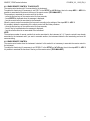
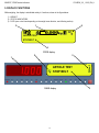
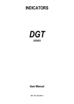
5. DISPLAY FUNCTIONS
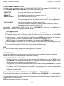
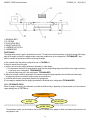
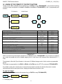
While weighing, the display is subdivided mainly in 3 sections, shown in the figure below:
1) WEIGHT
2) STATUS INDICATORS
3) DATA (one or two lines depending on the weight zoom function; see following section).
2
1
2
ARTICLE TEST
STOP BELT
3
1
2
CPWE display
2
ARTICLE TEST
STOP BELT
3590E display
14
3
3590EXT, CPWE series indicators
E-CHECK_03 _12.05_EN_U
5.1 WEIGHT ZOOM
The zoom function allows to increase the size of the weight digits, in order to ease the reading from a distance; with the
active zoom, the data is shown on a single line.
STOP BELT
Through the << ZOOM.W >> step, one can disable/enable the function and set a delay which determines the activation
mode:
- always active function (with delay equal to 0), or
- disabled function at the pressing of a key and reenabled automatically when the keyboard inactivity time reaches the
configured delay period (with delay greater than 0).
5.2 STATUS INDICATORS
SYMBOL ON LCD DISPLAY
FUNCTION
The weight detected by the weighing system is near the zero, included within the interval of
–1/4 and +1/4 of the scale division.
The weight is unstable.
The displayed weight is a GROSS WEIGHT (depending on the software language).
The displayed weight is a NET WEIGHT.
A tare value has been acquired.
A manual tare value has been entered.
Unit of measure in use: ton, kilogram, gram, pounds, millilitres, or millivolts.
Active weighing range, see section ―MULTIRANGE FUNCTION‖.
Active scale (always 1).
Indicates that a specific function of the instrument is active.
Battery charge level: see section ―BATTERY LEVEL INDICATION‖.
Active during the configuration of the date and time.
Locked keyboard, see section "DISABLING THE KEYBOARD‖.
In the HELP menu these respectively indicate whether a key is unlocked or locked in the
SETUP level (<< En.KEYS >> step, see section ―HELP MENU―).
The Fn key has been pressed.
The 2nd F key has been pressed.
Transmission of the data to the printer serial port under way.
Inside the step, these respectively indicate an unselected or selected parameter.
Active calculator function, see section ―CALCULATOR‖.
15
3590EXT, CPWE series indicators
E-CHECK_03 _12.05_EN_U
5.2.1 BATTERY LEVEL INDICATION
The indicator is able to recognise whether it is powered by mains or by battery, and indicate its charge level; to enable the
battery level indication, one should configure the << Bt.Stat. >> step.
The charge level is shown during weighing by the battery symbol.
-
: charged battery.
-
: partially charged battery.
- : discharged battery: connect the indicator to the mains for recharging the battery (if provided for by that model) or
replacing the battery. Furthermore, the "Low.bat " message will appear for a few seconds on the display (voltage at
minimum level).
The indicator shows also when the battery is being recharged (if provided for the model):
RECHARGE PHASE:
…
COMPLETED RECHARGE:
NOTES:
- During the recharge the instrument can be normally used.
- The instrument automatically turns off when the voltage goes below the minimum level.
5.3 MODIFICATION OF THE DISPLAYED DATA
The data shown on the display can be modified by selecting one of the various visualisations provided for by the indicator.
CPWE
The selection of the visualisation with non active weight zoom, and the one with active zoom (see section ―WEIGHT
ZOOM‖) are independent from each other.
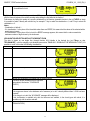
SELECTION OF VISUALISATION WITH NON ACTIVE WEIGHT ZOOM
The data is shown on two lines; by pressing in sequence the 2nd F and F9 keys (associated with the function 107), with the
weighing cycle disabled (see section ―ENABLING / DISABLING THE WEIGHING CYCLE‖), one scrolls in order the
following visualisations:
NUMBER VISUALISATION
0
- Gross or net weight on the scale
- Active semiautomatic tare (PT if manual tare)
1
2
EXAMPLE
GROSS
B1 TARE
- First article description or net weight
- Tolerance range (see section ―TOLERANCE
CHECK‖).
1.000kg
1.000kg
ARTICLE TEST
0.90 <> 1.10
NOTES:
- the ranges are shown in the database unit of measure (or in ml if a density different than 1.0000 has been
entered)
- if the range is not valid, the ―NO RANGE‖ message will be displayed
- this visualisation is available only with the tolerance test enabled, in the check types with article, it is
possible only with the article selected.
- First article or net weight description
- System status (see section ―SYSTEM STATUS
ARTICLE TEST
VISUALISATION‖).
STOP BELT
16
3590EXT, CPWE series indicators
3
E-CHECK_03 _12.05_EN_U
- Lot weighs total
- Accumulated lot total
T.WGH
0
T.LOT 0.000Kg
By linking the function to a direct key, see the << F.Keys >> step, it is possible to quickly recall a visualisation by digiting,
with the numeric keyboard, the relative number and pressing the key linked to the function.
Furthermore, by linking the number of a specific visualization to the function (preamble function in the << F.KEYS >> step),
it is possible to select it directly with a direct key, for example F1 key to select the visualization n.1, and F2 key to select the
visualization n. 2.
Notes:
- Visualisation of default 1.
- If in visualisation 1 in the place of the threshold values there are EEEEE, this means that the values of the selected article
weight are not correct.
- If in visualisation 3 in the place of the lot total, the EEEEE message appears, this means that the value exceeds the
maximum number of digits shown by the instrument.
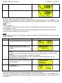
VISUALISATION SELECTION WITH ACTIVE WEIGHT ZOOM
The data is shown on one single line; through function 208, linkable to the desired key (<< F.Keys >> step,
TECH.MAN.REF.), with the weighing cycle disabled (see section ―ENABLING / DISABLING THE WEIGHING CYCLE‖) it is
possible to scroll in this order the following visualisations:
NUMBER VISUALISATION
EXAMPLE
0
Gross or net weight on the scale
NET
1
0.000kg
Active semiautomatic tare (PT if manual tare)
B1 TARE
2
0.000kg
First article description
ARTICLE TEST
3
4
NOTE: this visualisation is available with the selected article.
Tolerance ranges (available with the tolerance
test enabled, see section ―TOLERANCE
CHECK‖).
0.90 <> 1.10
NOTES:
- the ranges are shown in the database unit of measure (or in ml if a density different than 1.0000 has been
inserted)
- if the range is not valid, the ―NO RANGE‖ message will be displayed.
- this visualisation is available only with the tolerance test enabled, In the check types with article, it is
possible only with the article selected.
System status (see section ―SYSTEM STATUS
VISUALISATION‖).
STOP BELT
17
3590EXT, CPWE series indicators
5
E-CHECK_03 _12.05_EN_U
Lot weighs‘ total.
T. WGH:
6
0
Accumulated lot total.
T. LOT:
0.000Kg
By linking the function to a single key, it is possible to quickly recall a visualisation, by digiting from the numeric keyboard,
the relative number, and by pressing the key linked to the function.
Furthermore, by linking the number of a specific visualization to the function (preamble function in the << F.KEYS >> step),
it is possible to select it directly with a direct key, for example F1 key to select the visualization n.1, and F2 key to select the
visualization n. 2.
NOTES:
- Default visualisation: 1
- If in visualisation 3, in the place of the threshold values, there are EEEEE, this means that the values of the selected
article weight are not correct.
- If in visualisation 6, in the place of the lot total, there is the message EEEEE, this means that the value exceeds the
maximum number of displayable digits by the instrument.
3590E
The selectable info are shown in the LCD display; by pressing in sequence the 2nd F and F9 keys, one scrolls in order the
following visualisations:
NUMBER VISUALISATION
0
- Gross or net weight on the scale
- Active semiautomatic tare (PT if manual tare)
1
2
3
EXAMPLE
NET
B1 TARE
- First article description or net weight
- Tolerance range (see section ―TOLERANCE
CHECK‖).
0.000kg
0.000kg
ARTICLE TEST
0.90 <> 1.10
NOTES:
- the ranges are shown in the database unit of measure (or in ml if a density different than 1.0000 has been
entered)
- if the range is not valid, the ―NO RANGE‖ message will be displayed
- this visualisation is available only with the tolerance test enabled, in the check types with article, it is
possible only with the article selected.
- First article or net weight description
ARTICLE TEST
- System status (see section ―SYSTEM STATUS
VISUALISATION‖).
STOP BELT
- Lot weighs total
- Accumulated lot total
T.WGH
T.LOT
0
0.000Kg
By linking the function to a direct key, see the << F.Keys >> step, it is possible to quickly recall a visualisation by digiting,
with the numeric keyboard, the relative number and pressing the key linked to the function.
Furthermore, by linking the number of a specific visualization to the function (preamble function in the << F.KEYS >> step),
it is possible to select it directly with a direct key, for example F1 key to select the visualization n.1, and F2 key to select the
visualization n. 2.
18
3590EXT, CPWE series indicators
E-CHECK_03 _12.05_EN_U
Notes:
- Visualisation of default 1.
- If in visualisation 1 in the place of the threshold values there are EEEEE, this means that the values of the selected article
weight are not correct.
- If in visualisation 3 in the place of the lot total, the EEEEE message appears, this means that the value exceeds the
maximum number of digits shown by the instrument.
CUSTOMIZED VISUALISATION
Through function 120 combinable with the desired key (<< F.KEYS >> step, TECH.MAN.REF.), one enables the custom
display function. The display shows:
ART. : ARTICLE TEST
STA. : STOP BELT
TXT0 : TEXT 0
TXT1 : TEXT 1
In which:
―ART.‖ indicates article description.
―STA.‖ indicates system status.
―TXT0‖ indicates the contents of the input text 0.
―TXT1‖ indicates the contents of the input text 1.
Each row contains up to 22 characters.
By pressing Fn + F9 it`s possible to directly enable the function; by pressing 2ndF + F9 it`s possible to change the
visualizations on the LCD display to disable the function.
NOTE: The function is only for 3590E indicator.
19
3590EXT, CPWE series indicators
E-CHECK_03 _12.05_EN_U
5.3.1 SYSTEM STATUS VISUALISATION
Below there are the statuses shown on the display, in the visualisation of the SYSTEM STATUS.
In order to select this visualisation, refer to the previous section.
STATUS
MOTOR ALARM
WEIGHT ALARM
WAITING
RESTART WAIT
START WAIT
IN WEIGHING
PACK EVACUATION
OUT OF TOLERANCE
NON WEIGHED PACK
WEIGHED PACK
POSITIONING
STOP BELT
WEIG.TIME LAPSED
DESCRIPTION
Locked weighing cycle: the EMERGENCY / MOTOR LOCK input (IN.6) is active for a minimum
time set in step << BLK.MOT >>; the cycle restarts as soon as the input has been disabled.
Locked weighing cycle: the instrument has detected a weight greater than the Maximum capacity
+ 9d or less than -100d, for a minimum time period configured in step << W.UN.OV >> (only with a
time period greater than 0), One should restore the weight and supply an impulse on the
RESTART input (IN.4) in order to reenable the cycle.
The instrument is ready for weighing, and waits for the obscuring of the pack presence photo cell
(IN 2) (functioning with photo cell), or for a weight greater than the minimum weigh threshold
(functioning without photo cell).
One should supply an impulse on the RESTART input (IN.4) in order to reenable the cycle after an
error condition.
One should supply an impulse on the RESTART input (IN.4) in order to enable the cycle with the
belts stopped at start-up.
The instrument is acquiring the weight of the object.
The instrument has carried out the various cycle phases and proceeds with the evacuation of the
weighed object.
During the compulsory weight correction, a restart impulse has been given with the weight out of
tolerance (see section ―CORRECTION OF THE OUT OF TOLERANCE WEIGHT‖).
The object to be weighed on the weighing belt has not been weighed because the consensus from
downstreasm has been disabled (IN.1) or the input voltage of the indicator has gone missing
during the weigh acquisition. One should supply an impulse on the RESTART input (IN.2) in order
to reenable the cycle.
The object to be weighed on the weighing belt has been weighed before disabling the consense
from downstream (IN.1) or from a missing input voltage of the indicator. One should supply an
impulse on the RESTART input (IN.4) in order to reenable the cycle.
After the pack presence photo cell is obscured (IN 2), the instrument waits of the pack positioning
time before acquiring the weigh.
Disabled weighing cycle (see section ―ENABLING / DISABLING THE WEIGHING CYCLE‖), in the
simple weighing condition, with the stopped belts.
During the weigh acquisition, the weigh has been unstable for a time period greater than the value
set in step << T.M.PES >> (only if the weighing at halt has been selected). One should supply an
impulse on the RESTART input (IN.4) in order to reenable the cycle.
20
3590EXT, CPWE series indicators
E-CHECK_03 _12.05_EN_U
5.4 MESSAGES
While using the indicator, it is possible to incur into the following errors:
INSIDE THE SET-UP OR MENU
MESSAGE
C.Er. – 8.03
C.Er. – 36
C.Er. – 37
ERROR:
UNSTABLE WEIGHT
ErPnt
SAVE AND EXIT?
SURE?
DESCRIPTION
When carrying out the multirange or multidivisional calibration, the ranges have not been
entered in an increasing manner (RANGE 1 < RANGE 2 < RANGE 3).
During the calibration some internal negative points have been calculated:
- the calibration point is less than the zero point.
- the signal is negative (check the connections)
During the calibration some internal points less than the minimum value have been calculated:
- the calibration point is equal to the zero point.
- A capacity too high in relation to the division has been set.
The weight results to be unstable and therefore can not be acquired; press ENTER to display
the menu of the next possible operations or C to exit from the step.
During the acquisition of a calibration point, a null value from the converter has been read.
The instrument requests the saving when exiting the set-up; press ENTER to confirm or C to
not continue.
The instrument requests a confirmation before proceeding: press ENTER to confirm or C to not
continue.
AT START-UP
MESSAGE
Err – 36
No Cal.
Er – 37
alternately with No.Cal
Er – 39
Er – 40
Er – 41
hW-Err
EXECUTION
AUTOZERO
DESCRIPTION
The points of the converter are negative:
- the calibration point is less than the zero point.
- the signal is negative (check the connections).
One must execute a TECHNICAL DEFAULT (DfLt.t parameter of the SET-UP environment)
and carefully carry out the calibration
The converter points are less than the instrument‘s internal divisions; one must execute a
TECHNICAL DEFAULT (DfLt.t parameter of the SET-UP environment) and carefully carry out
the calibration.
Invalid calibration range number (there is the value 0 or values greater than 3); one must
execute a TECHNICAL DEFAULT (DfLt.t parameter of the SET-UP environment), if not
already executed previously, and carefully carry out the calibration.
The value 0 is in the ―range 1‖ parameter of the calibration; one must execute a TECHNICAL
DEFAULT (DfLt.t parameter of the SET-UP environment) and carefully carry out the
calibration.
The value 0 is in the ―diV 1‖ parameter of the calibration; one must execute a TECHNICAL
DEFAULT (DfLt.t parameter of the SET-UP environment) and carefully carry out the
calibration.
HARDWARE ERROR: software not compatible with the installed hardware; the hardware
expansion component is missing which allows the software to function.
―autozero at start-up‖ function is active (see section ―POWER SUPPLY & START-UP‖).
NOTE: if the Er – XX error appears after the indicator start-up; press the TARE key to enter in the SET-UP
environment.
21
3590EXT, CPWE series indicators
E-CHECK_03 _12.05_EN_U
IN WEIGHING
MESSAGE
WITH ZOOM NOT
WITH ZOOM
ACTIVE
ACTIVE
ARTICLE
NOT SELECTED
ART.NOT SELECTED
EXECUTION
AUTOZERO
STOP FOR WEIGH
ERRORS
EXECUTION AUTOZERO
ERRORS WEIGH
OUT OF TOLERANCE
NON VALID OR
UNSTABLE WEIGHT
NO ZERO CROSS
OR INSTABILITY
*** POWER OFF ***
RESET LOT?
INVALID TOLERANCE
THRESHOLDS
INVALID THRESHOLDS
TOLERANCE CHECK
DISABLED
DESCRIPTION
If the tolerance check has been enabled, one should select an
article in order to start the weighing cycle. This message indicates
that no article has been selected
―Autozero at start-up‖ belt function (see section ―WEIGHING
BELT AUTOZERO‖).
The number of weighs executed out of tolerance has reached the
set value (see section ―AUTOMATIC TARGET RECALCULATION
AFTER N WEIGHS WITHIN TOLERANCE‖).
During the compulsory weight correction, the restart impulse has
been supplied with the weight out of tolerance (see section
―CORRECTION OF THE OUT OF TOLERANCE WEIGHT‖).
Printing not possible with weight at 0, negative, unstable.
Printing not possible without having the weight pass by the net
zero or by instability.
Turning off of the instrument through the key (see section
―POWER SUPPLY & START-UP‖).
Request of lot total clearing (see section ―VISUALISATION AND
CLEARING OF THE ACCUMULATED TOTALS‖)
If the tolerance check has been enabled, one should set the valid
thresholds. This message indicates that a minimum threshold
exceeding a maximum threshold, has been inserted.
One is trying to select an article, but the tolerance test has not
been enabled.
IN THE WEIGHING IN THE WEIGHT SECTION
MESSAGE
-----ZERO
TARE
CLEAR
prn-on
GROSS
NET
LOCK
UNLOCK
DESCRIPTION
Under weigh -100d (with approved instrument) or over the Maximum Capacity + 9d.
Execution of scale zero (see section ―SCALE ZERO FUNCTION‖).
Tare execution (see section ―TARE FUNCTIONS‖).
Tare cancellation (see section ―TARE FUNCTIONS‖).
Turning on printer for maintenance (see section ―CONNECTION TO THE BATTERY
POWERED PRINTER‖).
Visualisation of the gross weight.
Visualisation of the net weight.
Tare lock or enabled keyboard function.
Tare lock or disabled keyboard function.
22
3590EXT, CPWE series indicators
E-CHECK_03 _12.05_EN_U
6. SCALE ZERO FUNCTION
With the weighing cycle disabled (see section ―ENABLING / DISABLING THE WEIGHING CYCLE‖), keep the ZERO key
pressed at length; the message "ZERO" appears on the LED display after which:
- If the weight on the scale is included in the percentage configured in the << 0.PErC >> step (TECH.MAN.RIF.), it is
zeroed;
- If the weight is not within this range, it will not be cleared and an error sound is emitted.
In the end the indicator automatically returns to the display of the weight present on the scale.
It‘s possible to execute the zero also with weighing cycle enabled, by using the function of ―WEIGHING BELT AUTOZERO‖
(see the section ―WEIGHING BELT AUTOZERO‖).
7. TARE FUNCTIONS
7.1 SEMIAUTOMATIC TARE
To tares any weight which is on the scale one should:
- remove the consensus from downstream (IN 1 = 0Vdc), if not excluded in the << diS.d.st >> step;
- press the TARE key.
The display shows “tArE” for an instant and then 0 (net weight); furthermore also the relative indicators are enabled.
The display shows therefore the gross weight value and the stored tare value.
In any case, a new operation automatically cancels and substitutes the previous one.
NOTE: The semiautomatic tare is acquired only if the weight is of AT LEAST ONE DIVISION AND IS STABLE (indicator
instability led is off) and VALID (In other words the UNDERLOAD and OVERLOAD conditions must not be created).
~
7.2 PRESET TARE
To enter the tare value, one should:
- remove the consensus from downstream (IN 1 = 0Vdc), if not excluded in the << diS.d.st >> step;
- with the keyboard, type the value (including the decimal point) and press TARE.
The indicator automatically subtracts the entered value from the displayed weight, (the relative indicators are enabled), as
long as it is not greater than the instrument‘s maximum capacity.
The display shows therefore the gross weight value and the stored tare value, identified with ―PT‖ (Preset Tare).
The operation can be made either with a loaded or unloaded platform.
In any case, when a new Tare value is entered, the preceding one is cancelled and substituted.
NOTE: In the printout, the manual tare is identified with ―PT‖ (Preset Tare).
7.3 CALCULATED MANUAL TARE
With the "CALCULATOR" function one can add or subtract from the current tare the result of an operation between two
values entered with the keyboard.
For the functioning specifics see the ―CALCULATOR‖ section.
7.4 TARE CANCELLATION
To cancel the stored tare:
- With an unloaded platform, press the TARE key.
- With loaded platform press in sequence the numeric 0 key and TARE.
- Press the C key (CAREFUL: this operation cancels also the executed reference).
7.5 LOCKED/UNLOCKED TARE
Normally, when a tare value has been entered (automatically, manually or from storage) by unloading the scale plate, the
display shows the tare value with a negative sign (LOCKED TARE). One can also choose that the tare value is cancelled
automatically, each time that the scale is unloaded (UNLOCKED TARE).
23
3590EXT, CPWE series indicators
E-CHECK_03 _12.05_EN_U
CONDITIONS FOR AUTOMATIC UNLOCKING:
In case of SEMIAUTOMATIC TARE, the net weight before unloading the scale may also be 0.
In case of MANUAL OR CALCULATED TARE or FROM DATABASE, the net weight before unloading the scale
must be of at least 2 stable divisions.
If the F5 key is pressed at length, it is possible to quickly lock/unlock the tare:
DISPLAY
LoCK
Unlock
MEANING
LOCKED TARE
UNLOCKED TARE
It is possible to carry out this setting or disable completely the tare operations through the << t.LocK >>
―LOCKED/UNLOCKED TARE‖ parameter of the SET-UP environment.
7.6 LIMITATION OF THE TARE FUNCTIONS
For specific requirements, it is possible to limit the functions of the tare with approved instrument; by setting ―YES‖ in the
<< D.SALE >> step.
- the SEMIAUTOMATIC TARE can not be modified with a manual or calculated tare, or one from database.
- the manual or calculated tare, or one from database must be entered or modified only with UNLOADED scale.
With approved instrument, the << D.SALE >> step is read only.
7.7 LINKING A KNOWN TARE VALUE TO AN ARTICLE
It is possible to link a known tare value to each article in the database; this value will be enabled with each selection of the
article.
See section ―ENTRY‖ for further details.
8. MULTIRANGE FUNCTION
The multi range functioning allows to subdivide the scale capacity in two or three ranges, each which is up to 3000
divisions, improving in this way the first range division in the dual range and the first two ranges in the triple range.
For example it is possible to approve the weighing system with:
- A single range: 6 kg capacity and 2 g division (3000 div.).
- Dual range: 6 /3 kg capacity and 2/1 g division (3000 + 3000 div.).
- Triple range: 15 / 6 / 3 kg capacity and 5/2/1 g division (3000 + 3000 + 3000 div.).
NOTE: For the approval of the weighing system in dual and triple ranges the cell must have better technical features in
comparison to the cell used for the approval in a single range.
This functioning is indicated by the enabling of the symbol which identifies the range in which one is working: W1 first
range, W2 second range, W3 third range (if configured); by passing to the W2 range, the second range division is enabled;
by passing to the W3 range, the third range division is enabled, at this point the W1 first scale division is restored only by
passing the gross zero of the scale.
The multidivisional functioning is similar to multirange, but with the difference that a range division is enabled as soon as
one enters in its range interval (in other words without passing by the scale zero).
NOTE: The selection of the range number with multirange and multidivisional functioning is made during the indicator
calibration (TECH.MAN.REF.).
9. DISPLAY OF METRIC DATA (inFO)
The indicator is fitted with a function named ―INFO‖, thanks to which it is possible to view the configuration metric data:
- First range capacity, first range minimum weigh, first range division.
- Second range capacity, second range minimum weigh, second range division.
- Third range capacity, third range minimum weigh, third range division.
NOTES:
- The minimum weigh corresponds to 20 net weight divisions.
- The data of the second and third range appear only if actually configured.
24
3590EXT, CPWE series indicators
E-CHECK_03 _12.05_EN_U
To display the metric data:
By pressing 2ndF + C the display will show ―METROLOLOGIC INFORMATION‖.
- The display will show the number of the scale, the type of displayed data (―MAX‖ for the capacity, ―MIN‖ for the
minimum weigh, ―e‖ for the division) and its value.
- Press the F6 key to quickly scroll the following data in this order:
Capacity 1° range Minimum weigh 1° range Division 1° range Capacity 2° range ………
- Press the F7 key to scroll the previous data backwards.
- Press the ENTER key to view the metric data of the following range.
- Press the C key to return to weighing.
25
3590EXT, CPWE series indicators
E-CHECK_03 _12.05_EN_U
10. FILLING IN THE INPUT TEXT
The indicator offers the possibility of using 15 CONFIGURABLE INPUT TEXTS (for example LOT, OPERATOR, SHIFT,
etc.) in the F.ModE → tXt step (TECH.MAN.REF.), each contains the following steps:
- DESCRIPTION
- TEXT
- THRESHOLD
- MANDATORY INPUT
- ONLY VOID INPUT
the heading of the input text, up to 16 characters.
the contents of the input text, up to 32 content characters.
the length limit of the contents of the input text, from 1 to 32.
force to insert contents of the input text.
If the function is enabled, in the weighing phase, by pressing F4 key to modify the contents
of the programmed input texts, only when the contents is not null, exit from alphanumeric
input by pressing C key.
only access to the input text in which the contents is null.
If the function is enabled, in the weighing phase, by pressing F4 key only to modify the
programmed input texts in which the content is null.
When entered in the TECHNICAL SET-UP (see << tXt >>, TECH.MAN.REF.), these may be printed later on, if
programmed in the printouts; or these may be used as a reminder.
In the weighing phase:
1) Press F4 for an instant one can enter the contents of the programmed INPUT TEXTS:
2) The display shows ―in. XX‖ on the first line, in which XX is the index of the input text (from 0 to 14) THE HEADING
on the second line of the input text (or ―Empty…‖ if empty).
3) Use the arrow keys to select the text to be filled in and press ENTER: now one can enter the alphanumeric
text in the second line of the LCD display (see chapter ―ENTERING ALPHANUMERIC TEXT‖).
NOTE: The length of the enterable characters depend on the value set in the “THRESHOLD” step.
4) Press ENTER to store and pass on to the following stored TEXT; by confirming the last entered text one returns
automatically to the weigh functioning;
5) it is possible to exit also with the C key while in the text selection modification phase.
NOTE:
The entered texts remain in storage until these are substituted or cancelled.
If no text has been configured, the pressing of the F4 key has no effect.
COPY OF THE TEXT
After inserting an alphanumeric text, by pressing the F1 key, it will be possible to copy the contents and make these
available when making a new insertion through the pressing of the F2 key.
QUICK MODIFICATION OF AN INPUT TEXT
By linking the number of a specific input text to the function 113 (preamble function in the << F.KEYS >> step,
TECH.MAN.REF.), it is possible to access directly to the modification of it with a direct key, for example F1 key to
quickly access the text 0, and F2 key to quickly access the text 1.
Through function 121 to 130 combinable with the desired key (<< F.KEYS >> step, TECH.MAN.REF.), it`s possible
quickly to modify the contents in the input text 0 to 9.
For example, if the F1 key is associated with function 121, inserting a string of the characters from the external
keyboard, and then pressing the F1 key, the string of the characters will be automatically stored in the input text 0
and replace original characters.
QUICK CANCELLATION OF THE CONTENTS OF AN INPUT TEXT OR ALL THE INPUT TEXTS
Through function 131 combinable with the desired key (<< F.KEYS >> step, TECH.MAN.REF.), it`s possible quickly to
cancel the contents of the input text.
The function 131 is enabled, one is asked to insert the input text number to be cancel, if the number is inserted at 99, it will
cancel the contents of all the input texts.
NOTE: Only the contents of the input text is cancelled.
26
3590EXT, CPWE series indicators
E-CHECK_03 _12.05_EN_U
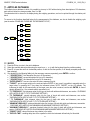
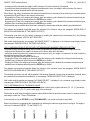
11. ARTICLES DATABASE
The indicator has a database in which it is possible to store up to 1000 articles having three descriptions of 20 characters;
each article is linked to a storage number, from 0 to 999.
The selected article is shown on the display during the weighing operations, and can be printed through the relative print
block.
To access to the functions described below for the management of the database, one has to disable the weighing cycle
(see the section ―ENABLING / DISABLING THE WEIGHING CYCLE‖).
F1
F1
New
F2
Edit
F3
Delete
F5
Print
Fn
Select
2nd F
Deselect
C
Clear
Art.dtb
./HELP
Help
11.1 ENTRY
1)
2)
3)
4)
Press the F1 key to enter in the article database.
Select the eventual desired position using the arrow keys (or with the keyboard type the position number).
Press F1 to insert the article in the desired position, or with the first free position, if an already occupied position has
been selected.
One should fill in the following fields (only the necessary ones are requested); press ENTER to confirm:
" DESCRIPTION 1": first description line (up to 20 characters);
" DESCRIPTION 2": second description line (up to 20 characters);
" DESCRIPTION 3": third description line (up to 20 characters);
"ENTER DENSITY": here one can enter the value, expressed in g/ml;
"TARGET": put the target weight on the scale and press ENTER. In any case it is possible to manually enter the
target value, by pressing the C key when the instrument shows "AUTO TARGET" on the LCD display. The
instrument is ready for the manual entry of the target; once the value is entered, confirm with ENTER; in case of
density different than 1, the entered value is expressed in ml;
"T1 THRESHOLD": first tolerance value (for the type of check with article and tolerances, see section ―CHECKING
WITH ARTICLE AND T1,T2,T3 TOLERANCE SETTING‖)
"T2 THRESHOLD": second tolerance value (for the type of check with article and tolerances, see section
―CHECKING WITH ARTICLE AND T1,T2,T3 TOLERANCE SETTING‖)
" T3 THRESHOLD": third tolerance value (for the type of check with article and tolerances, see section
―CHECKING WITH ARTICLE AND T1,T2,T3 TOLERANCE SETTING‖)
"MINIMUM THRESHOLD": minimum threshold value (for the type of check with article and tolerances, see section
―CHECKING WITH ARTICLE AND MINIMUM AND MAXIMUM THRESHOLD SETTING‖)
"MAXIMUM THRESHOLD ": maximum threshold value (for the type of check with article and tolerances, see
section ―CHECKING WITH ARTICLE AND MINIMUM AND MAXIMUM THRESHOLD SETTING‖)
"PRESET TARE": value of the known tare, relative to the article.
"EXP.DEL.TIME" : enabling delay time of the expeller for which the instrument will wait only for this article.
27
3590EXT, CPWE series indicators
E-CHECK_03 _12.05_EN_U
In fact, if one sets the ―Enable‖ parameter << Rit.Esp. >> step (TECH.MAN.REF.), the instrument will adopt the
expeller delay time of the selected article.
"ANALOGUE OUTPUT": value which the analogue output takes on for this article, useful for adjusting the belt
speed depending on the selected article (see section ―ANALOGUE OUTPUT (OPTIONAL)‖, TECH.MAN.REF.);
one enters the values of the digital / analogue converter (between 0 and 65535) to which a certain voltage or
current output value corresponds. The instrument keys take on the following functions:
ENTER
By pressing it once after entering a value, it activates the corresponding analogue output value,
(allowing its control) but remains still inside the step in case of a new modification. By pressing it a
second time (on the same entered value), confirms and exits the compilation of the article.
C
Allows to quickly clear the current value.
NUMERIC KEYS Allow to enter the values, from right to left.
If a digit greater than 65535 is entered, the instrument clears the entered value.
11.2 MODIFICATION
1)
2)
3)
4)
Press the F1 key to enter in the article database.
Select the storage to be modified by using the arrow keys (or with the keyboard type the storage number; the
LCD display shows the first corresponding DESCRIPTION line) and press F2.
Modify the desired fields, listed in the previous section.
Press the C key to return to weighing.
11.3 CANCELLATION
1)
2)
3)
4)
Press the F1 key to enter in the article database.
Select the storage to be cancelled by using the arrow keys (or with the keyboard type the storage number; the
LCD display shows the first corresponding DESCRIPTION line) and press F3.
The indicator requests a further confirmation: press ENTER to confirm or another key to cancel.
Press the C key to return to weighing.
11.4 PRINTING
1)
2)
Press the F1 key to enter in the article database.
Once inside the article database menu, press the F5 key. The LCD display shows the message ―PRINT?‖: confirm with
the ENTER key to print the entire article database which shows all the relative fields for each stored article.
11.5 SELECTION/UNSELECTION
To select a stored article, one can proceed in two ways:
1) Enter the article storage number using the numeric keyboard (if different than the 000 storage, see the following
section) and press F1: if an article is stored in the recalled position, the indicator display shows the message
―ARTICLE XXX SELECTED‖ (in which XXX indicates the number of the selected storage) and activates it.
2) Press for an instant the F1 key to enter in the article database:
- Select the storage using the arrow keys (or with the keyboard type the storage number; the LCD display
shows the first corresponding DESCRIPTION line).
- Press ENTER to activate the article.
To unselect a selected article, for an instant press the F1 key to enter in the article database and press 2nd F.
Before unselecting, a confirmation is requested: press ENTER to confirm or another key to cancel.
11.6 ENTRY, MODIFICATION AND QUICK SELECTION OF ARTICLE 000
It‘s possible to enter or modify quickly the article 000:
Type the number 0 using the numeric keyboard and press F1:
- The indicator is ready to enter/modify the article 000: once modified and confirmed with ENTER, it is also
selected. The modification has effect also in the database.
11.7 HELP
By pressing the ./HELP key, it‘s possible to see the keys list used in the menu.
The key list is automatically. If you want to see the keys list, in manual mode, use the arrow key (F6 and F7 ).
28
3590EXT, CPWE series indicators
E-CHECK_03 _12.05_EN_U
12. DATABASE ACCESS PASSWORD
In the SETUP (<< dtb.PWD >> parameter) one can set a password for access to the databases. A password will be
required only when one wants to insert, modify or delete an element of the file; for a moment the display shows the
message USER-PRESS KEY; afterwards, it will be no longer possible to make changes to the database.
To access the complete menu
Press any key DURING THE VISUALISATION OF THE ―USER-PRESS KEY‖: the instrument requests the entry of
the password (a number will appear).
Enter the password and confirm with ENTER.
If one does not know the password, one should give the random number to the manufacturer, who will give a
password valid ONLY FOR THAT RANDOM NUMBER.
13. WEIGHING PROCEDURES
The programme has been made to manage an automatic weighing cycle on belt, either static or dynamic, with tolerance
control, accumulation, and printing of the executed weighs.
The input/output allows for the automatic belt management for the handling, weighing, and selection or expulsion.
To start the automatic weighing operations, one should enable the weighing cycle as described in the following sections.
13.1 SYSTEM STATUS CONTROL
Its specific visualisation allows the control of the system status, in order to detect eventual errors which do not allow the
normal continuation of the operations.
To select this visualisation, refer to section ―MODIFICATION OF THE DISPLAYED DATA‖.
For this purpose, there are special error messages which will be displayed independently from the chosen visualisation, see
section ―MESSAGES‖.
Before starting the weighing cycle or during the weighing cycle, one should pay attention to this information, in order to
supply to the instrument the necessary commands for proceeding with the operations or restoring the system in the error
status.
13.2 ENABLING / DISABLING THE WEIGHING CYCLE
To enable the weighing cycle one should:
a) turn on the instrument with the electro mechanics disabled (- remove the consensus from downstream (IN 1 =
0Vdc), if not excluded in the << diS.d.st >> step; TECH.MAN.REF.).
b) select the article to be weighed (only if one is using the instrument in the tolerance check mode).
c) enable the consensus from downstream (IN 1 = 0Vdc), if not excluded in the << diS.d.st >> step;
The weighing and cadence belts will take on a specific condition (these can be still or in motion), depending on the
parameter set in step << ST.NSTR >>.
If the belts are stopped, in order to start the weighing cycle, one should supply a restart impulse (IN.4).
NOTE: If the belts are not enabled make sure that the electro mechanic system is correctly powered, verifying the system
status as described in the previous section.
To enable the weighing cycle with block for missing voltage, see section “CYCLE RESTORAL AFTER POWER
OUTAGE”.
To disable the weighing cycle one should disable the consensus from downstream (remove the running) for a time
greater than the one configured in step << BLK.D.ST >>: the weighing cycle is interrupted.
With the consensus from downstream excluded in the << diS.d.st >> step, the weighing cycle is always active.
To reenable the weighing cycle one should:
29
3590EXT, CPWE series indicators
a)
b)
E-CHECK_03 _12.05_EN_U
enable the consensus from downstream (IN 1 = 0Vdc), if not excluded in the << diS.d.st >> step.
press the RESTART/RESET button with belts stopped at the start-up (passo << ST.NSTR >> step set on ―STOP‖,).
NOTE:
With consensus from downstream (IN 1 = 0Vdc) not excluded in the << diS.d.st >> step, all keys take on their functions
and it‘s possible to turn the instrument off only with the weighing cycle disabled.
13.3 DESCRIPTION OF THE CYCLE PHASES
Once the cycle is enabled, the instrument enables the belts and is ready for the automatic acquisition of the weighs by
following the phases described in the following sections.
13.3.1 WEIGHT ACQUISITION
The instrument can acquire the weigh in four ways depending on how the system has been configured (see the
<< WGh.tyP >> step, TECH.MAN.REF.):
- at halt with a sensor,
- in motion with a sensor,
- in motion with two sensors
- without sensors.
13.3.1.1 AT HALT WITH 1 PHOTO CELL
The weight acquisition takes place with a halted weighing belt.
The weighing with a halted belt allows to obtain the best accuracy of the weighing system on the belt, but requests a
greater time for the weigh acquisition, and consequently causes a decrease of the weighing cadence.
DESCRIPTION OF THE SYSTEM
On the weighing belt installed on the scale, a photo cell (the START one) is installed, for checking the presence of the
object to be weighed and subsequent start of the weighing operations.
EXAMPLE:
LO
~
NET
g
1 WEIGH START PHOTO CELL
2 WEIGHING BELT
3 PLATFORM
4 CADENCE PHOTO CELL
30
Kg
t
/h
F
START STOP
GO
W1
W2
HI
W3
SP1
MENU
ENTER
SP2
C
ì
3590EXT, CPWE series indicators
E-CHECK_03 _12.05_EN_U
5 CADENCE BELT
6 EXPELLER BELT
7 WEIGHT INDICATOR
The cadence belt supplies the packs to the weighing belt with the possibility of managing their flow, as described in section
―MANAGEMENT OF CADENCE PHOTOCELL AND BELT‖.
FUNCTIONING
In the moment that the pack starts transiting on the weighing belt, in other words from the instant in which the pack
presence photo cell is obscured, the instrument:
1) Waits for the positioning of the pack
2) Halts the weighing belt
3) Waits for the weight stability
4) Acquires the weight
5) Continues with the subsequent cycle phases (proceed in the reading of the following sections)
6) Is ready to carry out a new weigh
It‘s possible to set a minimum duration of the stability condition (<< STB.WGT >> step, TECH.MAN.REF.): if the weight is
stable for a time greater than the one set, the instrument acquires the weigh otherwise it waits for the stability.
This setting can be useful when:
- The weight, after the belt halt, reaches right away the equilibrium but it stabilizes on its current value after a few seconds;
- One should acquire the weight of a material inside a container, carrying out the filling on the belt after the halt.
It‘s also possible to set a maximum duration of the instability condition (<< T.M.PES >> step, TECH.MAN.REF.): if the
weight is unstable for a time greater than the one set, the instrument:
- Enters in an error condition: the instrument enables the alarm for the configured time, and if the visualisation of the
SYSTEM STATUS is active, the ―TIME-OUT‖ message is displayed.
- Waits for its restoral: the operator can restore the weight stability and restart the cycle by supplying a restart impulse
(IN.4); the instrument will repeat the weighing operations from point 3.
13.3.1.2 IN MOTION WITH 1 PHOTO CELL
The weight acquisition takes place with the weighing belt in motion.
The weighing with the belt in motion allows a greater weigh acquisition speed, by obtaining in this way a greater weighing
cadence.
The vibrations due to the belt motion however cause oscillations on the weight, and a decrease of the weighing system
accuracy; this is compensated partially by the instrument during the special acquisition procedure, and partially by the
calculated filter and the optimisation executed during the configuration.
DESCRIPTION OF THE SYSTEM
See following section.
FUNCTIONING
In the moment in which the pack starts to transit on the weighing belt, in other words, from the instant in which the pack
presence photo cell is obscured, the instrument:
1) Waits for the positioning of the pack
2) Detects a series of weight values with the object in motion for a pre-established time interval (set in the << T.M.PES >>,
TECH.MAN.REF.)
3) Calculates the weight, averaging the detected weight values.
4) Proceeds with the subsequent cycle phases (proceed in the reading of the following sections)
5) Is ready to carry out a new weigh
13.3.1.3 IN MOTION WITH 2 PHOTO CELLS
The weight acquisition takes place in the same way as the previous mode, but the use of a second photo cell allows to take
advantage of all the possible weighing time depending on the pack that is to be weighed.
31
3590EXT, CPWE series indicators
E-CHECK_03 _12.05_EN_U
DESCRIPTION OF THE SYSTEM
On the weighing belt mounted on the scale, a photo cell is installed (the START one), for checking the presence of the
object to be weighed and for the consequent start of the weighing operations; furthermore, a second photo cell is used (the
STOP one), for checking the exit of the object to be weighed, and consequent end of the weighing operations.
EXAMPLE
LO
~
NET
g
Kg
t
/h
F
START STOP
GO
W1
W2
HI
W3
SP1
MENU
ENTER
SP2
C
ì
1. WEIGH START PHOTO CELL (first photo cell)
2. WEIGH STOP PHOTO CELL (second photo cell)
3. WEIGHING BELT
4. PLATFORM
5. CADENCE PHOTO CELL
6. CADENCE BELT
7. EVACUATING BELT
8. WEIGHT INDICATOR
FUNCTIONING
In the moment in which the pack starts to transit on the weighing belt, in other words, from the instant in which the pack
presence photo cell is obscured, the instrument:
1) Waits for the positioning of the pack
2) Detects a series of weight values with the object in motion until the end weigh photo cell is obscured
3) Calculates the weight, averaging the detected weight values.
4) Proceeds with the subsequent cycle phases (proceed in the reading of the following sections)
5) Is ready to carry out a new weigh
13.3.1.4 AT HALT WITHOUT PHOTO CELLS
The positioning and weight acquisition takes place with the weighing system at halt, and it is eventually put into action only
in the evacuation.
The trailing edge of the weight is used for starting the weigh acquisition and the leading edge for reenabling the weighing.
The weight acquisition takes place upon the reaching of the stability or upon a set time.
EXAMPLE WITH WEIGHING BELT
The weighing belt, mounted on the scale, is connected to the expulsion relay and to the tolerance relays, for the
management in the evacuation phase and subsequent end of the weighing operations.
EXAMPLE
32
3590EXT, CPWE series indicators
E-CHECK_03 _12.05_EN_U
1. WEIGHING BELT
2. PLATFORM
3. EVACUATING BELT
4. WEIGHT INDICATOR
FUNCTIONING
The weigh starts when the pack is positioned on the belt. The instrument tests the presence of the pack through the leading
edge of the weight, verifies if the weight variation obeys the conditions set in the configuration, TECH.MAN.REF., then
starts to execute the operations useful for achieving the weigh:
a) the eventual weigh time starts (configured in step << T.M.PES >>)
b) starts to acquire a set of weights
c) waits for one of the fine weigh conditions to take place, in other words:
1) the weight is stable, weight variation is in the range set in the configuration, TECH.MAN.REF.;
2) ends the weight time (set in the configuration, TECH.MAN.REF.).
d) When one of these conditions takes place, the instrument ends the weigh acquisition and calculates the best weigh.
averaging the closest consecutive weighs among the acquired ones.
e) continues with the following cycle phases (read the next paragraphs)
f) a new weigh is enabled when the weight goes below the threshold set in configuration (TECH.MAN.REF.)
13.3.1.5 IN MOTION WITH NO PHOTO CELL
The weight acquisition takes place with the weighing belt in motion.
The weight acquisition starts when the rising edge of the weight takes place. The new acquisition is enabled when the
falling edge of the weight takes place.
The data acquisition terminates either on the falling edge of the weight or when the set time expires.
The in motion operative mode allows a faster weigh acquisition; in this way a higher weigh rate is achieved.
The belt motion causes weight oscillation and provides deterioration in the weigh precision. This deterioration is
compensated by the instrument using the filter calculated in the system configuration phase.
EXAMPLE WITH WEIGHING BELT
The system is similar to the one with 1 or 2 photo cells, but it has no photo cells.
The pack presence check is achieved through the weight edges‘ monitoring.
33
3590EXT, CPWE series indicators
E-CHECK_03 _12.05_EN_U
1. WEIGHING BELT
2. PLATFORM
3. EVACUATING BELT
4. WEIGHT INDICATOR
5. CADENCE PHOTO CELL
6. CADENCE BELT
FUNCTIONING
The weigh starts when the pack is positioned on the belt. The instrument tests the presence of the pack through the leading
edge of the weight, verifies if the weight variation obeys the conditions set in the configuration, TECH.MAN.REF., then
starts to execute the operations useful for achieving the weigh:
a) the eventual weigh time starts (configured in step << T.M.PES >>)
b) starts to acquire a set of weighs
c) waits for one of the fine weigh conditions to take place, in other words:
1) the instrument checks for the pack absence monitoring the weight falling edge and verifies that the weight variation is
in the range set in configuration, TECH.MAN.REF.;
2) ends the weight time (set in the configuration, TECH.MAN.REF.).
d) When one of these conditions takes place, the instrument ends the weigh acquisition and calculates the best weigh
averaging the closest consecutive weighs among the acquired ones.
e) continues with the next cycle phases (read the next paragraphs)
f) a new weigh is enabled when the weight goes below the threshold set in configuration (TECH.MAN.REF.)
13.3.2 TOLERANCE CHECK
When the weigh is acquired, the instrument can follow two different ways, depending on the parameter set in the tolerance
range enabling step << TST.TOL >>:
TOLERANCE TEST
ACTIVE
NOT ACTIVE
*****************************************************************************************************************************
ACTIVE TEST
The instrument carries out the tolerance check, that is, it checks if the weight is within the tolerance interval set in the
configuration, then:
34
3590EXT, CPWE series indicators
E-CHECK_03 _12.05_EN_U
- IF THE WEIGHT IS WITHIN THE TOLERANCE INTERVAL, the instrument executes the following sequence of
operations:
Totalization
Weigh result display
Belt Stop (if set)
Evacuation
- IF THE WEIGHT IS NOT WITHIN THE TOLERANCE RANGE:
the instrument executes the following sequence of operations:
Weigh correction (if set)
Totalization
Weigh result display
Belt Stop (if set)
Evacuation
Automatic ejection (if set)
For operational details read the next sections.
The tolerance check interval may be set in 3 ways, as described in the next paragraphs and set in the step
<< CHECK.t >>.
In the following paragraphs the tolerance check range setting is described, as well as the functions related to the
tolerance checking.
NOT ACTIVE TEST
*****************************************************************************************************************************
Once the weight is acquired, the instrument executes the totalization procedure, see paragraph ―TOTALIZATION‖.
13.3.2.1 CHECKING WITH ARTICLE AND T1,T2,T3 TOLERANCE SETTING
The tolerance range is assigned by setting in the article the target weight (TARGET) and the tolerance values (T1, T2, T3).
The latter values are weight values to be added or subtracted from the target in order to determine the weight thresholds.
When filling in the article, the following fields have to be inserted: TARGET weight, and the tolerance values necessary for
setting the tolerance range and for enabling the relays‘ functions (see paragraph ―WEIGH RESULT INDICATION AND
ENABLING OF THE LINKED OUTPUTS‖).
The weighing cycle starts only if the article is selected: by enabling the consensus from downstream (IN.1), the following
error message is displayed ―ARTICLE NOT SELECTED‖.
With invalid weight thresholds the message ―NO RANGE SELECT.‖ is displayed in the tolerance range display location
(see paragraph ―MODIFICATION OF THE DISPLAYED DATA‖).
It is possible to view every tolerance threshold related to the selected article: through the function 300, linkable to the
desired key (<< F.Keys >> step, TECH.MAN.REF.), with disabled weigh cycle (see paragraph ―ENABLING / DISABLING
THE WEIGHING CYCLE‖), the display shows:
T3 Disable
1.000kg
Tolerance threshold with related weight threshold
Indication of enabled/disabled tolerance, for determining the tolerance range and the
tolerance relay management
Scroll with the arrow keys the desired tolerance; press the C key to exit.
13.3.2.2 CHECKING WITH ARTICLE AND MINIMUM AND MAXIMUM THRESHOLD SETTING
The tolerance range is assigned by setting in the article the minimum and the maximum weight thresholds. The range is
assigned as follows:
35
3590EXT, CPWE series indicators
E-CHECK_03 _12.05_EN_U
- by setting both the thresholds, the weight is within tolerance if its value is within the 2 thresholds
- by setting the minimum threshold only (maximum threshold equal to zero), the weight is within tolerance if its value is
between the minimum threshold and the full scale capacity.
When filling In the article, the minimum and maximum thresholds have to be entered, their values may be modified quicker
by pressing the F2 and F3 keys in the weighing environment,
- By pressing the F2 key in the weighing environment, when the weighing cycle is disabled, the minimum threshold may be
modified; insert the desired value and press the ENTER key to confirm.
- By pressing the F3 key in the weighing environment, when the weighing cycle is disabled, the maximum threshold may be
modified; insert the desired value and press the ENTER key to confirm.
The thresholds may be modified when the article is selected, the inserted thresholds are copied in the selected article.
The minimum and maximum thresholds govern the activation of the tolerance relays (see paragraph ―WEIGH RESULT
INDICATION AND ENABLING OF THE LINKED OUTPUTS‖).
The weighing cycle starts only if the article is selected: by enabling the consensus from downstream (IN.1), the following
error message is displayed: ―ARTICLE NOT SELECTED‖.
With invalid weight thresholds, the message ―NO RANGE SELECT.‖ is displayed in the tolerance range display location
(see paragraph ―MODIFICATION OF THE DISPLAYED DATA‖).
13.3.2.3 CHECKING WITHOUT ARTICLE AND FAST MINIMUM AND MAXIMUM THRESHOLDS SETTING
The tolerance range is assigned setting (without article management) the minimum and maximum weight thresholds:
- setting both the thresholds, the weight is in tolerance if its value is within the 2 thresholds
- setting the minimum threshold only (maximum threshold equal to zero), the weight is in tolerance if its value is within the
minimum threshold and the scale capacity.
The setting is executed pressing the F2 and F3 keys,
- Pressing the F2 key in the weighing environment, when the weighing cycle is disabled, the minimum threshold may be
modified; insert the desired value and press the ENTER key to confirm.
- Pressing the F3 key in the weighing environment, when the weighing cycle is disabled, the maximum threshold may be
modified; insert the desired value and press the ENTER key to confirm.
The minimum and maximum thresholds define the activation of the tolerance relays (see paragraph ―WEIGH RESULT
INDICATION AND ENABLING OF THE LINKED OUTPUTS‖).
The weighing cycle starts only with valid thresholds: if the minimum threshold is greater than the maximum threshold, when
the consensus from downstream is enabled (IN.1), the message ―THRESHOLDS NOT VALID‖ is displayed.
With invalid weight thresholds the message ―NO RANGE SELECT.‖ is displayed in the tolerance range display location
(see paragraph ―MODIFICATION OF THE DISPLAYED DATA‖).
13.3.2.4 DETERMINATION OF TOLERANCE RANGE
In the function mode with article and tolerances, it is possible to select which negative tolerance (-T3, -T2, -T1) and which
positive tolerance (+T3, +T2, +T1) set the valid range of the pack weight.
This function is useful when the negative tolerance value is different from the positive tolerance value, for instance when the
valid weight is within the -T2 and +T3thresholds.
In the technical set-up (<< SET.RNG >> step, TECH.MAN.REF.), one can set the tolerance range limits.
TARGET + T3
36
TARGET + T2
TARGET + T1
TARGET – T1
TARGET – T2
TARGET – T3
Below is an example in programming the combinations for obtaining the tolerance range shown in the figure. The weight is
valid only if it‘s between TARGET - T2 and TARGET + T3.
3590EXT, CPWE series indicators
E-CHECK_03 _12.05_EN_U
: tolerance range
WEIGHT < than (TARGET – T3) → 0
(TARGET – T3) ≤ WEIGHT < (TARGET - T2) → 0
(TARGET – T2) ≤ WEIGHT < (TARGET - T1) → 1
(TARGET - T1) ≤ WEIGHT ≤ (TARGET + T1) → 1 (Always at 1, not modifiable)
(TARGET + T1) < WEIGHT ≤ (TARGET + T2) → 0
(TARGET – T2) < WEIGHT ≤ (TARGET + T3) → 1
WEIGHT > di (TARGET + T3) → 0
The entry of the T1, T2, T3 threshold values is made when entering the article (see section ―ARTICLES DATABASE‖)
In order to achieve a tolerance check, an article has to be selected.
13.3.2.5 CHECKING QUANTITIES IN ml
When entering an article, it is possible to enter a density coefficient in order to check the volume quantity (ml) instead of in
weight (g, kg, lb, t); if this coefficient is equal to 1,0000 the check is made on the weight, otherwise it is made on the
volume.
!! IMPORTANT !!
In order to weigh in ml, calibrate the instrument in grams and set the database unit of measure in grams.
The target of the article is directly taken into consideration in ml as well as the relative tolerances.
By entering an article having a coefficient different from 1,0000, and pressing the 2nd F and then the F8 key it will be
possible to switch the value shown by the display between the gross and net volume.
When printing one will note that the data which normally has the database unit of measure with the unit in ml.
the ml indicator on the display will turn on indicating that the unit of measure is ml.
13.3.2.6 AUTOMATIC TARGET RECALCULATION AFTER N WEIGHS WITHIN TOLERANCE
This function allows to automatically recalculate the target of the selected article, after the scale has carried out a number of
consecutive weighs within the tolerance set in the << N.W.Tol >> step (TECH.MAN.REF.).
When the number is reached, the target of the selected article is set to the value corresponding to the average of the
totalized weighs within tolerance.
By setting 0, the function is disabled.
13.3.3 CORRECTION OF THE OUT OF TOLERANCE WEIGHT
By enabling the correction of the weight, or the mandatory correction of the weight, in the << TYP.ESP >> step, if the weight
is out of tolerance, the instrument stops automatically the weighing belt after the weigh.
The alarm output OUT3 is also enabled for the set time (<< ALARM >> step) and on the display the message ―CONFIRM
WEIGHT‖ appears.
At that point the instrument executes two possible operations, depending if the correction or mandatory correction is set.
NON MANDATORY CORRECTION OF THE WEIGHT
The operator can:
37
3590EXT, CPWE series indicators
-
E-CHECK_03 _12.05_EN_U
correct the weight before the restart of the belt, by adding or removing material in order to have the weight within the
tolerances.
not correct the weight and remove manually the pack;
not correct the weight and leave the instrument to execute the automatic expulsion of the pack.
By giving the restart impulse (IN.4) with a stable weight the instrument:
acquires automatically the weight in static mode
executes the tolerance check on the new executed weigh
executes the totalization (only if the operator has not removed manually the pack)
executes the automatic expulsion if the weight is within the tolerance
NOTE:
Once the RESTART impulse is given, the instrument re-enables the weighing belt (OUT2), without checking if the manual
expulsion of the out of tolerance weigh is carried out, and executes in any case, the automatic expulsion.
MANDATORY CORRECTION OF THE WEIGHT
The operator MUST correct the weight before the restart of the belt, by adding or removing material in order to have the
weight within the tolerances.
By giving the restart impulse (IN.4) with a stable weight the instrument:
acquires automatically the weight in static mode
executes the tolerance check on the new executed weigh
At that point
- if the weight is within the tolerances the instrument executes the following operations:
Totalization
Weigh result indication
Evacuation
- if the weight is out of the tolerance range, the instrument remains in the weight correction status. By giving the RESTART
impulse, the message ―OUT OF TOLERANCE‖ is shown.
In this way the final weight is always within the tolerances and consequently the expulsion is never carried out.
13.3.4 TOTALIZATION
The program‘s purpose is to manage the automatic totalization of the acquired weighs: once the weigh is acquired and the
tolerance check and weight correction (depending on the configured functioning mode) are executed, it is automatically
totalized if the following conditions are not respected:
- With an approved instrument, the acquired NET weight is at least of 20 divisions.
- With a non approved instrument, the acquired NET weight is greater than 0.
The totalized weight is automatically accumulated in the instrument‘s total (PARTIAL, GENERAL, GRAND TOTAL and LOT
TOTAL), and the weighs progressives relative to the totals previously indicated increase.
Furthermore, if the article is active, the instrument increases both the total and the weighs progressive relative to the
selected article.
NOTE: the scale totals (PARTIAL, GENERAL, GRAND TOTAL and LOT TOTAL), are not depending on the selected
article.
13.3.4.1 TOTALIZATION OF ONLY THE WEIGHS WITHIN TOLERANCE
By setting the tolerance check function it is possible to choose if only the weighs within the tolerances have to be totalized
(see << tot.typ >> step, TECH.MAN.REF.). Therefore only the weighs within tolerance are printed, and the totals are
incremented, only if the weigh is within tolerance.
13.3.4.2 VISUALISATION AND CLEARING OF THE ACCUMULATED TOTALS
38
3590EXT, CPWE series indicators
E-CHECK_03 _12.05_EN_U
Each total can be momentarily viewed on the display or cleared independently through the printout, linking the function
corresponding to the desired step (<<F.Keys >> step, TECH.MAN.REF.):
TOTAL
PARTIAL TOTAL
GENERAL TOTAL
GRAND TOTAL
ARTICLE TOTAL (only with selected article)
TOTAL LOT
ALL TOTALS (except the lot total, and the zeroed article total is
relative to the selected article)
FUNCTION CODE FOR
VISUALISATION
403
406
409
412
-
FUNCTION CODE FOR
RESETTING
405
408
411
414
417
415
!! IMPORTANT !!
With the consensus from downstream excluded in the << diS.d.st >> step, TECH.MAN.REF., the totals and progressives
can be zeroed with the weighing cycle disabled, in other words, with instrument in lock from downstream status (IN. 1 =
0Vdc).
By recalling one of the clearing functions, the instrument requests a confirmation before proceeding with the cancellation:
press ENTER to clear, C for continuing to accumulate.
It‘s possible to disable the confirmation request, in the F.Mode >> totAL >> Reset step, TECH.MAN.REF..
In case of visualisation of the total, the instrument automatically exits the function after a few seconds.
NOTES:
- The clearing of the weight total causes also the reset of the relative number of weighs.
- The weight data of the cleared total will be updated only with the subsequent totalisation.
- The ARTICLE TOTAL is article specific, in other words, there is a total for EACH ARTICLE USED.
The other totals are GENERIC, and can be cleared INDEPENDENTLY ONE FROM THE OTHER (i.e. if one clears the
Grand total, with the following totalisation, the other totals will continue to increment, while the Grand total will restart
from 0).
13.3.4.3 CLEARING AND AUTOMATIC PRINTING OF THE PARTIAL TOTAL AFTER N WEIGHS
This function allows to automatically clear the partial total, after the scale has carried out a number of consecutive
totalisations (both in and out of tolerance) set in the << n.W.PRNT >> step (TECH.MAN.REF.).
The relative weight data is also printed (see section ―PRINTOUTS‖).
By setting 0, the function is disabled.
If the article is selected, the instrument prints and clears the article total instead of the partial total, and prints the relative
weight data (see section ―PRINTOUTS‖).
13.3.4.4 ADDITIONAL VALUE
Through function 400, combinable with the desired key (<< F.Keys >> step, TECH.MAN.REF.), it‘s possible to set a value
of up to 6 digits, which is summed to each totalisation, and can be recalled in the printing. The same value is linked
independently to three total types (PARTIAL, GENERAL, and GRAND TOTAL), in other words, it is possible to print three
different values which will be cleared with the clearing of the relative total.
13.3.4.5 TICKET PROGRESSIVE
Through function 402, combinable with the desired key (<< F.Keys >> step, TECH.MAN.REF.), it‘s possible to modify or
clear the TICKET PROGRESSIVE (up to 5 digits).The TICKET PROGRESSIVE is a progressive number which increments
of one UPON THE FIRST TOTALISATION SUBSEQUENT TO THE CLEARING OF THE PARTIAL TOTAL.
Furthermore through function 401, combinable with the desired key (<< F.Keys >> step, TECH.MAN.REF.), it is possible to
set the number of digits with which the TICKET PROGRESSIVE will be printed.
39
3590EXT, CPWE series indicators
E-CHECK_03 _12.05_EN_U
The number of settable digits varies from 4 to 16, organised in this way:
- if the actual digits of the total are less than the number of digits set in this step, the difference is filled with some
spaces.
- if the actual digits are greater than the number of digits set in this step, only the ones actually entered are taken into
consideration (counting from right to left).
The alignment of the total fields is on the left.
NOTE: The number of settable digits DOES NOT INCLUDE the comma.
13.3.5 WEIGH RESULT INDICATION AND ENABLING OF THE LINKED OUTPUTS
After the totalization procedure it is possible to show on the display, for a time set in the << T.W.VIS >> step, the totalized
weight (in the weight box) and a message that indicates the result of the weigh, with the eventual weigh number if the
weight is totalized (in the information section).
MESSAGE
WITH INACTIVE
WITH ACTIVE
ZOOM
ZOOM
OVERLOAD WEIGHT
WEIGHT NOT VALID
UNDER 20e
OVER T3+
T.WGH. G00000001
> T3+ T.WGH.00000001
OVER T2+
T.WGH.00000001
> T2+ T.WGH.00000001
OVER T1+
T.WGH.00000001
> T1+ T.WGH.00000001
IN TOLERANCE
T.WGH.00000001
IN TOL. T.WGH.00000001
UNDER T1T.WGH.00000001
< T1- T.WGH.00000001
UNDER T2T.WGH.00000001
< T2- T.WGH.00000001
UNDER T3T.WGH.00000001
< T3- T.WGH.00000001
OVER Tmax
T.WGH.00000001
> Tmax T.WGH.00000001
IN TOLERANCE
T.PES.00000001
IN TOL. T.WGH.00000001
UNDER Tmin
T.WGH.00000001
< T1- T.WGH.00000001
DESCRIPTION
It is not possible to totalize the weight greater than the maximum
capacity + 9d.
With approved instrument, it is not possible to totalize the weight
lower than 1d.
With approved instrument, it is not possible to totalize the weight
greater than zero, but lower than 20e.
These indicate the position of the weight in respect to the set
thresholds, and the eventual weighing number if the weight is
totalized, in the check with article and tolerances.
These indicate the position of the weight in respect to the set
thresholds, and the eventual weighing number if the weight is
totalized, in the check with or without article and setting of the
minimum and maximum thresholds.
The instrument has furthermore 7 tolerance outputs, in order to command, for example, an external traffic light, or a sorter.
After the totalization procedure, the output corresponding to the tolerance level in which the weight is detected, is activated;
the activation time of the output is configurable (<< TRF.LGT >> step).
40
3590EXT, CPWE series indicators
E-CHECK_03 _12.05_EN_U
In case of belt stop (see section ―STOP AND RESTART OF THE BELTS‖) the activation time is frozen, and the output
remains active; in that way it is possible to select the product in the evacuation phase also in case of belt stop. The time
restarts when the belts are restarted.
The managed tolerance outputs depend on the set functioning.
Only OUT10 on
TARGET + T3
Only OUT10 on
TARGET + T2
Only OUT9 on
TARGET + T1
Only OUT5 on
TARGET – T1
Only OUT8 on
TARGET – T2
Only OUT7 on
TARGET – T3
Only OUT7 on
OUTPUTS MANAGED IN THE FUNCTIONING WITH ARTICLE AND TOLERANCES
It is possible to define, in configuration phase (<< SET.THS >> step), the tolerance outputs to be managed, by decreasing
the tolerance levels; by enabling the tolerances, one defines the desired tolerance levels.
Below one finds a programming example of the combinations for managing 5 tolerance levels with correspondent outputs:
Under TARGET – T2, from TARGET - T2 to TARGET – T1, from TARGET – T1 to TARGET + T1, from TARGET + T1 to
TARGET + T2, over TARGET + T2.
WEIGHT < of (TARGET – T3) → 0
(TARGET – T3) ≤ WEIGHT < (TARGET - T2) → 1
(TARGET – T2) ≤ WEIGHT < (TARGET - T1) → 1
(TARGET - T1) ≤ WEIGHT ≤ (TARGET + T1) → 1 (Always at 1, not modifiable)
(TARGET + T1) < WEIGHT ≤ (TARGET + T2) → 1
(TARGET – T2) < WEIGHT ≤ (TARGET + T3) → 1
WEIGHT > di (TARGET + T3) → 0
One enters the T1, T2, T3 threshold values during the article insertion (see section ―ARTICLES DATABASE‖).
To have the check with tolerances, in fact, the article must be selected.
MANAGED OUTPUT IN THE FUNCTIONING WITH OR WITHOUT ARTICLE AND SETTING OF THE MINIMUM AND
MAXIMUM THRESHOLDS
The following outputs are managed to obtain 3 tolerance levels: weight under minimum threshold (OUT8), weight in
tolerance (OUT5), weight over maximum threshold (OUT9).
The entry of the thresholds is carried out during the article insertion or directly in the weighing phase (see section
―TOLERANCE CHECK‖).
13.3.6 STOP AND RESTART OF THE BELTS
Once the weight is totalized it could be necessary to stop (or leave stopped) the belts:
a) after a weigh out of tolerance, to allow the manual expulsion (if the << TYP.ESP >> step);
b) after every weigh, to allow eventual processings (by enabling the stop after the weigh stop in the << WGh.stp >> step);
c) after a number of weighs out of tolerance, in order to allow the system verification.
On the other hand, the instrument restarts (or leaves active) the weighing and cadence belts and proceeds with the
evacuation and the eventual automatic expulsion.
For the details on the belt stop mode and the following restart, continue the reading of the following sections.
13.3.6.1 STOP OF BELTS FOR WEIGH OUT OF TOLERANCE / MANUAL EXPULSION
41
3590EXT, CPWE series indicators
E-CHECK_03 _12.05_EN_U
This function stops automatically the weighing belt for weigh out of tolerance, allowing the manual expulsion of the pack (if
enabled in the << TYP.ESP >> step).
The generic OUT 3 alarm output is furthermore enabled for the set time (<< ALARM >> step) and the ―WAIT RESTART‖
message appears on the display.
To exit from the error status, one has to give a RESTART impulse (IN.4): the belts restart instantaneously.
NOTE:
Once the restart impulse is given, the instrument reactivates the weighing belt (OUT2), without controlling that the expulsion
of the pack out of tolerance is effectively carried out.
13.3.6.2 STOP OF BELTS AFTER EVERY WEIGH
It is possible to decide if the weighing belt must be always stopped after the weight acquisition and wait a restart impulse
(IN.4) before reactivating it, allowing eventual processings before the evacuation; see the << WGh.stp >> step.
The ―WAIT RESTART‖ message appears on the display.
To restart the belts one has to give a RESTART impulse (IN.4): the belts restart instantaneously.
13.3.6.3 STOP OF BELTS AFTER A NUMBER OF WEIGHS OUT OF TOLERANCE
This function stops automatically the weighing belt when a number of consecutive out of tolerance weighs (set in the <<
n.W.STOP >> step) is reached.
By setting the 0 value, the function is disabled.
The generic OUT 3 alarm output is furthermore enabled for the set time (<< ALARM >> step) and the ―STOP FOR WEIGH
ERRORS‖ message appears on the display.
To exit from the error status, one has to give a RESTART impulse (IN.4): the belts restart instantaneously.
13.3.7 EVACUATION AND AUTOMATIC EXPULSION
Once the belts restart, the instrument carries out the evacuation and the eventual automatic expulsion of the pack (if it is
enabled in the << TYP.ESP >> step), on other words:
- the set evacuation time starts (<< EVAC. >> step), useful for the eventual weighing belt autozero (see following section),
- it waits the activation delay of the expulsion output (OUT4) (set in the << R.ESP. >> step or in the article if the
<< Rit.Esp. >> step is enabled); after that, it activates the expulsion output (OUT4) for the set time (<< I.ESP >> step).
13.3.8 WEIGHING BELT AUTOZERO
The automatic zero function of the weighing belt allows to automatically restore the gross zero of the instrument during the
weighing cycle, by locking automatically the belts for the required time, if necessary.
The automatic zero can enter into function:
automatically, when the cycle is re-enabled and the weight is dfferent from zero, if it has been enabled the << 0.START >>
step.
automatically, when the number of minutes (since last zeroing) set in the << 0.BELT >> step configured on TIME
(TECH.MAN.REF.) have elapsed:
- if one sets the 0 value, the autozero never enters into function automatically;
- if one sets the n (>0) value, if the weight is different from 0, the instrument executes the autozero function. The minutes
counting starts when the instrument is started and restarts when a zero or a tare is executed.
The zero function is executed also when the cycle is disabled.
Once the set minutes have passed, if the system is in the weighing phase of a pack, the autozero procedure is
executed when the weighing is completed.
automatically, when the number of weighs (in tolerance as well as out of tolerance) set in the << 0.BELT >> step
configured on WEIGHS (TECH.MAN.REF.) have been executed:
42
3590EXT, CPWE series indicators
-
-
E-CHECK_03 _12.05_EN_U
if one sets the 0 value, the autozero never enters into function automatically;
if one sets the 1 value, at the end of each weigh the instrument waits for the evacuation time (<< EVAC >> step,
TECH.MAN.REF.) and executes the autozero function if
a) the belt is empty (instrument in ―PACK WAIT‖ status, no pack on the belt or in ―POSITIONING‖)
and
b) the weight is different from 0 (belt out of zero)
if one sets the n (>1) value, the instrument executes the autozero function after having completed the number of
configured weighs, n
manually, at the end of the eventual weigh being made, if the ZERO key has been pressed during the weighing cycle.
It is possible to decide to execute the automatic zero with the belt stopped or in motion << 0.type >>, (TECH.MAN.REF.).
PROCEDURE:
If the automatic zero procedure has been activated, the instrument maintains the weighing belt active for the evacuation
time
(<< EVAC. >> step (TECH.MAN.REF.)), so that the weighed pack can evacuate from the weighing belt, and it locks the
cadence belt if a pack is detected in front of the cadence photocell; the ―AUTOZERO EXECUTION‖ message appears on
the display.
Once this time has passed, the automatic zero of the belt is made, in two possible ways:
stopped:
- the weighing belt is stopped
- wait for the weight stability
- automatic zero of the belt
- restart of the weighing and cadence belts (if stopped)
in motion:
- the instrument leaves the weighing belt active
- wait for the weight stability
- automatic zero of the belt
- restart of the cadence belt (if stopped)
CONDITIONS FOR ZEROING
Independently from the automatic zero execution way, the weight can be zeroed only if it is within the percentage set in the
<< 0.PErC >> step (TECH.MAN.REF.) and with a stable weight.
Otherwise the instrument searches the zero for a set time (during which the display shows the ―AUTOZERO EXECUTION‖
message) at the end of which it emits an error sound signal: the automatic zero has not been made.
With automatic zero at time or at the re-enabling of the weighing cycle, the system goes into alarm condition, the display
shows the ―AUTOZERO FAILED‖ message and a RESTART impulse is required to restart. Once the RESTART impulse is
given, the automatic zero enter into function.
With automatic zero at weighs, the system doesn‘t go into alarm condition and allows the pack to continue.
If a tare is active, the automatic zero of the belt is not executed.
13.4 CYCLE LOCK AND INTERRUPTION OF THE WEIGH (NON WEIGHED PACK)
During the functioning it is possible that the cycle is locked during the weigh acquisition, by verifying one of the lock
conditions described in the following sections.
Once the system is restored, and the cycle is eventually re-enabled, the instrument verifies if the acquisition of the weigh
was stopped before the lock and it executes the following operations:
- if the acquisition is not terminated:
1) the ―NON WEIGHED PACK‖ message appears depending on the selected visualization (see section
―MODIFICATION OF THE DISPLAYED DATA‖);
2) a RESTART impulse is required in order to restart: the operator can now remove manually the weight for its
repositioning on the cadence belt, in order to acquire again the weight.
43
3590EXT, CPWE series indicators
-
E-CHECK_03 _12.05_EN_U
NOTE: Once the RESTART impulse is given, the instrument activates the weighing belt (OUT2), without controlling if
the pack has been removed; in any case, the instrument carries out the automatic expulsion in order to remove the non
weighed pack but without totalising.
if the acquisition is terminated
1) the ―WEIGHED PACK‖ message appears depending on the selected visualization (see section ―MODIFICATION
OF THE DISPLAYED DATA‖);
2) a RESTART impulse is required to restart: the instrument will resume the cycle phases at the point in which these
were interrupted.
NOTE: in case of downstream block or motor block, if the belts in motion at start-up are set (<< ST.NSTR >> step),
when the cycle is re-enabled the instrument restarts automatically without showing the ―WEIGHED PACK‖ message
and without waiting for the RESTART impulse.
13.4.1 DOWNSTREAM BLOCK
The system can handle the automatic disabling of the cycle from the downstream of the belt, when in the belt downstream
lock condition due to processing or error.
If it is not possible to manage the disabling of the cycle at the end of the weigh, in order to avoid the cancellation of the
weigh in progress, it can be useful to set a delay time of the downstream lock (<< BLK.D.ST >> step): the instrument waits
for the set time period to pass before disabling the cycle; during this time, furthermore, the instrument disables
automatically the cycle if the weigh is terminated.
Set a minimum time equal to the belt transition time.
13.4.2 EMERGENCY / MOTOR LOCK
Through the EMERGENCY / MOTOR LOCK input (IN.6) it is possible to manage an external signal for the instantaneous
cycle lock, caused by a generic EMERGENCY condition or motor lock condition
When the signal is activated, the instrument disables the cycle, activates the generic alarm (OUT3) for the configured time
and the ―MOTOR ALARM‖ message appears on the display.
It is possible to set a minimum time of the signal to disable the cycle, avoiding eventual noise (see << BLK.MOT >> step).
13.4.3 UNDERLOAD / OVERLOAD WEIGHT LOCK
Through the underload / overload weight lock function, it is possible to disable the cycle if a weight lower than -100d is
detected (with approved instrument) or greater than the maximum weight + 9d, for a time greater than the value set in the
<< W.UN.OV >> step.
By setting the time at 0 the function is disabled.
13.5 CYCLE RESTORAL AFTER POWER OUTAGE
When turning on the indicator after a power outage with a pack on the weighing belt, the instrument does not carry out the
automatic zero at start-up, allowing the eventual evacuation or manual removal of the pack: the ―POWER OUTAGE‖
message appears depending on the selected visualization (see section ―MODIFICATION OF THE DISPLAYED DATA‖).
By enabling the consensus from downstream the instrument verifies if the acquisition of the weigh is terminated before the
power outage and it executes the following operations:
- if the acquisition is not terminated:
1) the ―NON WEIGHED PACK‖ message appears depending on the selected visualization (see section
―MODIFICATION OF THE DISPLAYED DATA‖);
2) a RESTART impulse is required to restart: the operator must remove manually the weight for the repositioning on
the cadence belt, in order to acquire again the weight.
3) Once the RESTART impulse is given, the instrument executes the autozero at start-up, as described in section
―POWER SUPPLY & START-UP‖.
NOTE: Once the RESTART impulse is given, the instrument executes the autozero, without controlling if the pack has
been removed.
-
if the acquisition is terminated
44
3590EXT, CPWE series indicators
E-CHECK_03 _12.05_EN_U
1) the ―WEIGHED PACK‖ message appears depending on the selected visualization (see section ―MODIFICATION
OF THE DISPLAYED DATA‖);
2) a RESTART impulse is required to restart: the operator must remove manually the weight.
3) Once the RESTART impulse is given, the instrument executes the autozero at start-up, as described in section
―POWER SUPPLY & START-UP‖.
NOTA: The instrument carries out the autozero at start-up if the function is enabled and the weight on the scale is within the
percentage set in the << Auto 0 >> step (TECH.MAN.REF.).
13.6 MANAGEMENT OF CADENCE PHOTOCELL AND BELT
It is possible to manage a cadence photo cell, which gives the possibility to stop the cadence belt each time that the
foreseen cadence is not respected.
This function allows to avoid that, during the weighing of a package, the next pack arrives on the weighing belt,
compromising the weigh under way.
From the moment in which the cadence photo cell (IN.3) is obscured, if the instrument is in weigh acquisition, in execution
of the belt automatic zero or the weighing belt is stopped, the cadence belt is stopped (off).
The cadence belt is re-enabled only after the instrument has acquired the weigh, has finished executing the automatic zero
or the weighing belt has been re-enabled.
It is also possible to set a delay time between the two packs (<< 2.PAC >> step); in this case, if the cadence photo cell is
obscured by a pack, and, within the configured time, it is obscured by another pack, the instrument stops the cadence belt
and maintains it in this status until the delay time between the two packs has passed. By setting a time of 0 sec., this control
is not executed.
Therefore, take care not to obscure accidentally the cadence photocell during the weighing.
When a pack is in weighing and the delay time between the two packs ends, the next pack is positioned on the belt,
regardless of whether the first pack is in positioning or in weighing. Therefore one has to set properly the weight time
<< T.M.PES >>.
13.7 ALARM OUTPUT MANAGEMENT
There are 6 cases which determine the conditions for the alarm activation:
- Weight out of tolerance (only if the manual expulsion has been selected), with << TST.TOL >> step enabled.
- The number of weighs out of tolerance has reached the value set in the << n.W.STOP >> step
- Weight unstable for a time greater than the value set in step << T.M.PES >> (only if the weighing at halt is selected) .
- Pack not weighed at the restart of the belts (after the lock from downstream which took place before the end of the
weigh).
- Weight greater than the maximum Capacity + 9d or less than -100d, for a time greater than the value configured in
step << W.UN.OV >> (only with time greater than 0).
EMERGENCY / MOTOR LOCK input (IN6) active for a time greater than the value configured in step
<< BLK.MOT >>.
The impulse duration is set in << ALARM >> step.
14. PRINTOUTS
The instrument is fitted with different print functions, which may be used while weighing, and of 30 print formats, in other
words, 30 different memory storages, each of which contain a programmable printout.
The print executed by these functions depends on the print format linked to it; see the following section for the linkages.
The format linking function allows to execute various printouts, by changing the linked format each time.
The available functions are:
SIMPLE PRINTOUT:
- Programmable printout Through the PRINT key F5 key one prints the linked format, without executing the totalisation.
45
3590EXT, CPWE series indicators
E-CHECK_03 _12.05_EN_U
With the APPROVED instrument:
- The printing works if there is a NET WEIGHT of at least 20 divisions.
- The printout is re-enabled depending on how the << react >> parameter is configured
With the NON APPROVED instrument:
- The printing works if there is a NET WEIGHT greater than zero.
- The simple printout is always active (the programming of the << react >> parameter is not taken into
consideration).
TOTALIZATION WITHIN TOLERANCE, OUT OF TOLERANCE, WITHOUT TOLERANCE TEST - Programmable printout
After a totalisation, depending on the check result, the printing is made of one of the linked formats (WITHIN TOLERANCE,
OUT OF TOLERANCE WITHOUT TOLERANCE TEST).
With the APPROVED instrument:
- The printing works if there is a NET WEIGHT of at least 20 divisions.
With the NON APPROVED instrument:
- The printing works if there is a NET WEIGHT greater than zero.
PRINTING OF THE HEADING (upon the first executed totalisation)
- Programmable printout If a format is linked to the (―FIRST TOTALISATION HEADING‖) first totalization, will cause the printing of this format and
then the format linked to the totalisation function.
PARTIAL TOTAL
- Programmable printout By pressing the F8 key, the resetting of the PARTIAL TOTAL and the printing of the linked format are made.
Alternatively, it‘s possible to automatically execute the function, as described in section ―CLEARING AND AUTOMATIC
PRINTING OF THE PARTIAL TOTAL AFTER N WEIGHS‖.
NOTE: the instrument allows to use a progressive number increasing every time the partial total is cleared, see section
―TICKET PROGRESSIVE‖ for further details.
GENERAL TOTAL
- Programmable printout By pressing the F9 key the resetting of the GENERAL TOTAL and the printing of the linked format are made.
GRAND TOTAL
- Programmable printout By pressing the F10 key, the resetting of the GRAND TOTAL and the printing of the linked format are made.
SELECTED ARTICLE TOTAL
- Programmable printout With the selected article, by pressing the 2ndF and F1 keys the resetting of the ARTICLE TOTAL is made and the linked
format is printed.
LOT TOTAL
- Programmable printout by pressing the 2ndF and F3 keys, or in alternative by pressing at length the RESET / RESTART button (IN.4), the LOT
TOTAL is automatically cleared and the relative format is printed.
RESULT OF THE CALCULATOR
- Programmable printout Once terminated the operation with ―CALCULATOR‖ function the linked format is printed. See section ―CALCULATOR‖.
46
3590EXT, CPWE series indicators
E-CHECK_03 _12.05_EN_U
14.1 LINKING OF THE FORMATS TO THE PRINT FUNCTIONS
Through function 200, combinable with the desired key (<< F.KEYS >> step, TECH.MAN.REF.), one accesses the linking
of the print formats (configurable in the SetuP >> SeriAL >> Prn.FMt step TECH.MAN.REF.) to the 12 programmable print
functions:
Print function
200
S.F. 01
Linked format
F.
01
F7
C
...
ENTER
F6
S.F. 11
Print function
SIMPLE PRINTOUT
TOTALISATION WITHIN TOLERANCE
TOTAL LOT
Key
F5
Automatic entry
2ndF and F3
sequence
Automatic entry
2ndF and F1
sequence
F8 or Automatic
entry
F9
F10
Automatic entry
Automatic entry
Automatic entry
Automatic entry
HEADING OF THE FIRST TOTALISATION
SELECTED ARTICLE TOTAL
PRINTING THE PARTIAL TOTAL
PRINTING THE GENERAL TOTAL
PRINTING THE GRAND TOTAL
CALCULATOR (see section ―CALCULATOR‖)
TOTALISATION WITHOUT TOLERANCE TEST
TOTALISATION OUT OF TOLERANCE
PRINT UPON TURNING ON
Linked step
S.F.01
S.F.02
S.F.03
S.F.04
S.F.05
S.F.06
S.F.07
S.F.08
S.F.09
S.F.10
S.F.11
S.F.12
!! IMPORTANT !!
With the consensus from downstream excluded in the << diS.d.st >> step, TECH.MAN.REF., the print functions recalled by
key or input are possible only with a disabled weighing cycle, in other words, with consensus from downstream (IN. 1 =
0Vdc).
The instrument is fitted with 30 print formats, in other words, 30 different storages, each of which contain a programmable
printout.
The formats are programmable in the SEtuP >> SEriAL >> Prn.FMt step in the SET-UP environment (TECH.MAN.REF.).
It‘s possible to quickly link a stored format to each print function listed in the table; this function allows also to execute
various printouts with the same print function, changing the linked format from time to time.
TO LINK THE FORMAT:
Recall function 200, combinable with the desired key (<< F.KEYS >> step, TECH.MAN.REF.).
200
S.F. 01
F.
01
The display shows:
47
3590EXT, CPWE series indicators
XX
E-CHECK_03 _12.05_EN_U
in which:
XX indicates the number of the function to which the print format is linked.
Select the print function (for example S.F. 01) through the arrow keys and press the ENTER key
Once entered, the display shows:
XX
in which:
XX indicates the number of the format to be linked to the function.
Type the format number and press ENTER.
NOTE: In order to not link any format to a vector one should enter the number 00.
14.1.1 QUICK LINKING OF THE FORMATS
By linking the number of a specific print function to the function 200 (preamble function in the << F.KEYS >> step,
TECH.MAN.REF.), it is possible to access directly to the modification of it with a direct key, for example F1 key to quickly
link the S.F. 1, and F2 key to quickly link the S.F. 2.
Furthermore for some print functions the desired formats can be quickly linked by setting directly the corresponding code
(function) to the desired key (<< F.KEYS >> step, TECH.MAN.REF.) without having to program the preamble::
CODE
QUICK LINKING FUNCTION
PRINT FUNCTION
200
Format linking to the Simple Printout (Prn.Fmt)
S.F.
01
201
Format Linking to the Totalisation (SND.FMT)
S.F.
02
TO QUICK LINK THE FORMAT:
Recall the desired print function, by pressing the linked key (<< F.KEYS >> step, TECH.MAN.REF.).
The display shows:
XX in which:
XX indicates the number of the format to be linked.
Type the format number and press ENTER.
NOTE: In order to not link any format to a print function one should enter the number 00.
14.2 LOT WEIGHS REPORT
Through the print functions described in the previous section, it is possible to create a report of the sampling made, by
printing a heading, the weight of each weighed object and the lot end, with all the statistical data of the weighs of the lot toal
and the accumulated total.
14.2.1 PRINTING OF THE HEADING
The data which is configured for the format linked to the ―FIRST LOT TOTALIZATION HEADER ‖ function allows to create
an independent print format which is printed as a heading when the first totalization is done. It is useful for printing the
COMPANY HEADING or other DESCRIPTIONS, when it is not necessary to print these in a single accumulation operation.
48
3590EXT, CPWE series indicators
E-CHECK_03 _12.05_EN_U
IND.ART. 0
XL PACKAGE
TARGET
5.000kg
START DATE AND TIME
20/01/05
12:08:48
-----------------------WEIGH
NET
1
5.002kg
14.2.2 TOTALIZATION
The data configured for the totalisation formats (WITHIN TOLERANCE, OUT OF TOLERANCE WITHOUT TOLERANCE
TEST) allows to create various formats for each outcome of the check; depending on the outcome of the check, the relative
format is printed. It is useful to print all the totalised weights by eventually indicating the weighs out of tolerance.
2
3
4
5
5.002kg
5.002kg
5.002kg
5.002kg
14.2.3 TOTAL LOT
The data configured for the ―LOT TOTAL‖ format allows to create a format containing all the statistical data of the weighs of
the lot total and the accumulated lot total, which is printed as a LOT TOTAL, see section ―VISUALISATION AND
CLEARING OF THE ACCUMULATED TOTALS‖.
-----------------------AVERAGE WEIGHT 5.0020kg
STD. DEV.
2.3967kg
WEI. ABOVE T1
0
WEI. ABOVE T2
0
WEI. ABOVE T3
0
WEI. UNDER T1
0
WEI. UNDER T2
0
WEI. UNDER T3
0
OK WEIGHS
6
MAX WEIGHT
5.002kg
MIN WEIGHT
5.002kg
T.LOT.WEI.
5
T.LOT.NET
15.010kg
END DATE AND TIME
20/01/05
14:15:20
14.3 REPETITION OF THE LAST EXECUTED PRINTOUT
By pressing in sequence the 2ndF and F5 keys the last executed printout is repeated; this function can not be executed two
times.
14.4 STANDARD PRINTING FORMATS
The << DEF.PRN >> parameter of the set-up environment allows to enable the standard printouts for the TPR printer.
NOTE: By enabling these printouts all the formatted print formats will be CANCELLED and will be SUBSTITUTED by the
standard formats, linked to the print functions.
49
3590EXT, CPWE series indicators
E-CHECK_03 _12.05_EN_U
Below are the standard printouts of the instrument:
WEIGHS CYCLE REPORT
(WITH ACTIVE ARTICLE AND
TOLERANCE CHECK)
REPORT START
(WEIGHING CYCLE
BEGINNING)
(<< Prn.F.4 >>)
TOTALISED
WEIGHS
(IN THE LOT TOTAL)
(<< Prn.F.2 >> o
<< Prn.F.10 >>)
REPORT END
(WEIGHING CYCLE
END)
(<< Prn.F.3 >>)
THE ZEROING OF
THE LOT TOTAL
WILL ENSUE
WEIGHS CYCLE REPORT
(WITHOUT ARTICLE AND
TOLERANCE CHECK)
JOHN SMITH LTD.
JOHN SMITH LTD.
157 INDEPENDENCE AVE.
LONDON
157 INDEPENDENCE AVE.
LONDON
ART.IND.
0
XL PACKAGE
TARGET 5.000kg
TOTALISED
WEIGHS
(<< Prn.F.9 >>)
BEGIN TIME DATE
20/01/05
12:08:48
-----------------------WEIGH
NET
1
5.002kg
2
5.002kg
3
5.002kg
4
5.002kg
5
5.002kg
-----------------------WGT. AVG.
5.0020kg
STD. DEV.
0.0000kg
WEIG. OVER T1
0
WEIG. OVER T2
0
WEIG. OVER T3
0
WGT. UNDER T1
0
WGT. UNDER T2
0
WGT. UNDER T3
0
WEIGHS OK
6
WGT. MAX
5.002kg
WGT. MIN
5.002kg
T.LOT.WGTS.
5
T.LOT.NET
25.010kg
END TIME DATE
20/01/05
14:15:20
50
START TIME DATE
20/01/05
12:08:48
-----------------------WEIGH
NET
1
5.002kg
2
5.002kg
3
5.002kg
4
5.002kg
5
5.002kg
-----------------------WGT. AVG.
5.0020kg
STD. DEV.
0.0000kg
WGT. MAX
5.002kg
WGT. MIN
5.002kg
T.LOT.WGTS.
5
T.LOT.NET
25.010kg
END TIME DATE
20/01/05
14:15:20
3590EXT, CPWE series indicators
E-CHECK_03 _12.05_EN_U
ARTICLE TOTAL
(<< Prn.F.5 >>)
PARTIAL TOTAL
(<< Prn.F.6 >>)
NET PART. T.
GROS. PART. T.
TARE PART. T.
WGTS PART. T.
ADD. PART. T.
21/01/05 - 08:26:05
JOHN SMITH LTD.
157 INDEPENDENCE AVE.
LONDON
ART. IND.
XL PACKAGE
50x30x10
0
T . ART NET
T . ART GROSS
T . ART TARE
T . ART WGTS.
21/01/05 - 08:26:05
50.00kg
50.00kg
0.00kg
25
GENERAL TOTAL
(<< Prn.F. 7 >>)
NET GEN. TOT.
GROS. GEN. TOT.
TARE GEN. TOT.
WGTS GEN TOT.
ADD. GEN. TOT.
21/01/05 - 08:26:05
GRAND TOTAL
(<< Prn.F.8 >>)
NET GRAND T.
GROS. GRAND T.
TARE GRAND T.
WGTS GRAND T.
ADD. GRAND T.
21/01/05 - 08:26:05
50.00kg
50.00kg
0.00kg
25
0
PRINT KEY
(<< Prn.F. 1 >>)
JOHN SMITH LTD.
157 INDEPENDENCE AVE.
LONDON
ART. IND.
XL PACKAGE
GROSS
TARE
NET
20/01/05
50.00kg
50.00kg
0.00kg
25
0
0
2.000kg
0.000kg
2.000kg
12:08:48
51
50.00kg
50.00kg
0.00kg
25
0
3590EXT, CPWE series indicators
E-CHECK_03 _12.05_EN_U
15. OTHER FUNCTIONS
15.1 DIAGNOSTIC PERIPHERALS
Through function 118 combinable with the desired key (<<F.Keys >> step, TECH.MAN.REF.), one enables the diagnostic
peripherals function.
The display shows:
OUT
IN
A.O.
10.000 kg
NOTE: If the expansion board is not present, 2 inputs and
4 outputs are displayed.
STATUS
DESCRIPTION
ANALOGIC OUTPUT(A.O)
OUTPUTS (OUT)
Analogic output value express in percent.
Status output, non active ( ) or active ( ).
INPUTS (IN)
Status input, non active (
SERIAL COMUNICATIONS
(Tx Rx)
The serial communication is active with external device.
) or active ( ).
Status of the weight:
WEIGHT
SCALE
with unloaded scale;
with unstable weight;
Number of the active scale ( always ) and the relative weight loaded.
15.2 COM DATA DIAGNOSTIC
Through function 119 combinable with the desired key (<< F.Keys >> step, TECH.MAN.REF.), one enables the Com data
diagnostic function. The display shows:
119 COM. DAT
119 COM. DAT
● COM1 (PC)
○ COM2 (PRN)
● ASCII
○ BINARY
In the first screen one selects the port on which the diagnostic control should be executed. While in the second screen, one
selects the code that one wants to use for viewing the data in transit.
RX: READ<0D><0A>
R
A
TX: ST, GS, 1.037,Kg<0D><0A>
When the data on the RX and TX reception and transmission lines are correctly displayed, then the functioning of the
relative serial line is considered to be correct.
NOTE: By pressing the ./HELP key, it‘s possible to see the keys list used in the menu.
52
3590EXT, CPWE series indicators
E-CHECK_03 _12.05_EN_U
15.3 CALCULATOR
Through function 114 combinable with the desired key (<<F.Keys >> step, TECH.MAN.REF.), one enables the calculator
function.
ADDITION
MULTIPLICATION
SUBTRACTION
Procedure:
- Enter the first value using the numerical keyboard.
- Press F1 to add, F2 to multiply, F3 to subtract the value.
TERMINATE THE OPERATION:
-
TYPE the second value and PRESS ENTER: the result will be shown for a few seconds on the display.
- TYPE the second value and PRESS TARE: the result will be shown for a few seconds on the display and will be added
(in the addition and multiplication case) or subtracted (in the subtraction case) to the current tare value.
- PRESS 2nd F: the NET weight on the scale will be used as a second value and the result will be shown for a few
seconds on the display.
In the end the printing of the ―CALCULATOR‖ will be executed anyway (see section ―PRINTOUTS‖).
To disable the calculator function, press the C key.
15.3.1 HELP
By pressing the ./HELP key, it‘s possible to see the keys list used in the menu.
The key list is automatically. If you want to see the keys list, in manual mode, use the arrow key (F6 and F7 ).
15.4 DISPLAY OF NET WEIGHT WITH SENSITIVITY X 10 (for testing use during calibration)
By pressing at length the F2 key one will view the net weight with sensitivity times 10 (press again at length the F2 key to
return to the normal visualisation).
NOTES:
- With approved indicator, the visualisation lasts about 5 seconds, after which it‘s disabled.
- The printout can only be done when the indicator has the standard sensitivity.
15.5 SETTING DATE / TIME
By pressing at length the F3 key ‗it‘s possible to quickly access the setting from the date / time of the instrument:
DAY ENTER MONTH ENTER YEAR ENTER HOUR ENTER MINUTES ENTER.
53
3590EXT, CPWE series indicators
E-CHECK_03 _12.05_EN_U
16. FUNCTIONING WITH ALIBI MEMORY
The alibi memory allows storing the executed weighs or the weights transmitted to the PC.
The stored values can then be recalled by the PC serial line or directly on the indicator‘s display for a following check.
The data filed with each weigh or upon each weight transmission is:
- Gross weight
- Tare
- Unit of measure
- Number of selected scale
The memorisation of a weigh takes place:
Following the reception of a command through the serial line, See section ―REQUEST WEIGHT VALUE
WITH WEIGH ID‖.
Upon the printing made with the F5 key or upon totalisation
By setting the Setup >> Serial >> Comprn >> Protoc. parameter on "ALIBI" (TECH.MAN.REF.).
Through the selection of the following TX.G.W or TX.N.W parameter, it is possible to choose whether to receive in
the response string to the PID command, either the gross or the net weight, along with the tare
It‘s possible also to transmit the string (weigh/ID) on the PC port, by setting the Setup >> Serial >> Com pc >>
Protoc. parameter on "ALIBI" (TECH.MAN.REF.).
NOTE:
In case of printing through the F5 key, the PID string is transmitted; while after at totalisation is made, the PIDM
string is transmitted. See section ―STRING FORMAT (WEIGHT/ID)‖ for the description of the two strings.
The identification of the weigh takes place through the ID code; a code is given to each weigh, allowing finding the weigh in
the database.
If the weight can be saved in the alibi, the numeric ID will be substituted with the message "NO".
The ID has the following format:
<Rewriting number > — < Weigh number >
- Rewriting number: number of 5 digits which may go from 0 to 00255; it indicates the number of complete rewritings of
the alibi memory.
- Weigh number: number of 6 digits which may go from 0 to 131071; it indicates the weigh number in the current rewriting
of the alibi memory
With each storage the weigh number is increased of 000001; when this reaches the value 131071, it restarts from 000000
and the rewriting number increases of 00001.
If the weigh can not be saved in the alibi, the numeric ID will be substituted with the message "NO".
For example:
If the weigh which has been stored is the following:
―PIDST,1,
1.000kg,
1.000kg,00126-131071‖
the following will be:
―PIDST,1,
1.000kg,00127-000000‖
1.000kg,
NOTE: it‘s possible to read the last 131071 weighs.
16.1 READING OF THE WEIGHS CARRIED OUT
Through function 418, combinable with the desired key (<< F.Keys >> step, TECH.MAN.REF.) it‘s possible to read a
carried out weigh, with weighing cycle disabled (see section ―ENABLING / DISABLING THE WEIGHING CYCLE‖):
first enter the rewriting number of the Alibi memory (rEW.id), confirm with ENTER, and then enter the weigh number (id)
and press ENTER. The ID is accepted only if valid.
54
3590EXT, CPWE series indicators
E-CHECK_03 _12.05_EN_U
If the alibi memory is empty the message ―EMPTY‖ appears on the display for a few instants; if the ID code entered is not
valid, the ―no id‖ message appears for a few instants, and then one exits the step.
By entering a valid ID code, the display shows the following data, selectable through the arrow keys :
Ch.X in which X is the selected channel number (always 1)
Gross weight value with unit of measure;
Tare weight value with unit of measure;
Net weight value with unit of measure.
Press C to exit the reading state of the weighs.
NOTE: It is possible to read the weigh carried out also through the PC serial line (see the ―WEIGH READING‖ serial
command in the following section).
16.2 SERIAL COMMANDS FOR MANAGING THE ALIBI MEMORY:
!! IMPORTANT !!
If the serial commands are transmitted in the format:
<ESC> command <STX>
in which: <ESC> is the ASCII decimal 27 character
<STX> is the ASCII decimal 02 character
Also the relative answer will be:
<ESC> string <STX>
16.2.1 REQUEST WEIGHT VALUE WITH WEIGH ID
The command which allows saving the weight in the alibi memory and the transmission is:
<II>PID<CRLF>
< II > = machine code, only if functioning in 485
PID = saving command of the weight data in the alibi memory
CR = ASCII 13 decimal code
LF = ASCII 10 decimal code
If the gross weight is equal or greater than zero and stable, the instrument will save the weight on the belt in the alibi
memory.
And the PID string (weight/id) will be transmitted on the PC port; this is described in the following section.
It is also possible to use the command
<II>PIDM<CRLF>
< II > = machine code, only if the 485 is used
PIDM = saving command of the weight data in the alibi memory
CR = ASCII 13 decimal code
LF = ASCII 10 decimal code
Differently than the previous command, this allows to save the last totalised weigh of the instrument in the alibi memory;
therefore by transmitting the PIDM command various times after the instrument has totalised a weigh, one will obtain
various times the saving of the same weigh until it has been substituted with a new one.
The instrument shows the PIDM (weight/id) string described in the following paragraph.
To avoid the saving of the same weigh various times, it is possible to use the <II>CIP<CRLF> command
(see the description of the serial commands (TECH.MAN.REF.)), and the number of the last stored weigh and the last
totalised weigh will be displayed.
By executing a check on the weigh progressive, it is possible to know when a new weigh has been totalised and, by
transmitting the PIDM command, and one obtains the saving of the new weight into the alibi memory.
In this way it is possible to store n weighs, avoiding to store the same weigh various times.
55
3590EXT, CPWE series indicators
E-CHECK_03 _12.05_EN_U
NOTE: - the weigh progressive given back by the CIP command, equals to the number of weighs of the lot total
- the command functions only in the weigh cycle
16.2.2 STRING FORMAT (WEIGHT/ID)
The PID and PIDM string contains all the information regarding the executed weigh.
DESCRIPTION OF THE PID STRING:
<ESC>[II]PIDSS,B,LLLLLLLLLLUU,YYTTTTTTTTTTUU,(ID | NO)
This string is given with each transmission of the PID commands
DESCRIPTION OF THE PIDM STRING:
[II]PIDMSS,B,LLLLLLLLLLUU,YYTTTTTTTTTTUU,(ID | NO))
in which:
[II]
485 address (only in the case of transmission in 485 mode)
PID OR PIDM
weigh memorisation command
SS
US unstable weight
ST stable weight
OL out of range weight (above)
UL out of range weight (less)
,
comma character
B
number of selected channel
,
comma character
LLLLLLLLLL
gross or net weight on 10 digits
UU
unit of measure
,
comma character
YY
2 spaces in case of null or automatic tare, PT in the case of preset tare
TTTTTTTTTT
tare weight on 10 digits
UU
unit of measure
,
comma character
ID | NO
XXXXX-YYYYYY or ―NO‖: weigh not stored in the alibi memory; the gross weight is
the negative or unstable result.
56
3590EXT, CPWE series indicators
E-CHECK_03 _12.05_EN_U
16.2.3 WEIGH READING
Command:
[II]ALRDXXXXX-YYYYYY <CR o CRLF>
in which
[II]
485 address (only in the case of 485 transmission mode)
XXXXX
rewriting number, from 0 up to 255.
ASCII 045 character
YYYYYY
ID code
<CR o CRLF> terminator, ASCII 13 and ASCII 10 characters
Instrument answer:
[II]B,LLLLLLLLLLUU,YYTTTTTTTTTTUU <CR o CRLF>
in which:
[II]
485 address (only in the case of 485 transmission mode)
B
number of selected channel
,
comma character, ASCII 044
LLLLLLLLLL gross weight on 10 digits
UU
unit of measure
,
comma character, ASCII 044
YY
2 spaces in the case of null tare or semi automatic tare, PT in the case of preset tare
TTTTTTTTTT tare weight on 10 digits
<CR o CRLF> Terminator, ASCII 13 and ASCII 10 characters
16.2.4 ALIBI MEMORY CANCELLATION (only with non approved instrument)
Command:
[II]ALDL <CR o CRLF>
in which
[II]
ALDL
CR
LF
485 address (only in the case of 485 transmission mode)
comando di cancellazione dell'alibi memory
carriage return (ASCII 13 decimal code)
line feed (ASCII 10 decimal code)
Instrument answer:
[II]ALDLOK <CR o CRLF>
if the cancellation has been carried out effectively
[II]ALDLNO <CR o CRLF>
if the cancellation has not been carried out effectively
57
3590EXT, CPWE series indicators
E-CHECK_03 _12.05_EN_U
DECLARATION OF CONFORMITY
This device conforms to the essential standards and norms relative to the applicable
European regulations. The Declaration of Conformity is available in the web site
www.diniargeo.com
WARRANTY
The instrument has a TWO-YEARS warranty from the date of delivery. This includes
labour and parts free of charge for INSTRUMENTS THAT ARE DELIVERED TO
THE SELLER'S MAIN OFFICE and applies only if the breakdown is NOT attributable
to the purchaser (for example, due to improper use) and is NOT attributable to the
shipping.
If on-site service is requested (or is necessary) for any reason, the technician's
travel expenses will be the purchaser's responsibility: travel time and travel
expenses as well as board and lodging (if necessary).
If the instrument is shipped through a shipping company, the round-trip shipping
expenses are the buyer's responsibility.
This WARRANTY IS VOID if breakdowns result from service performed by
unauthorized personnel, if the unit is connected to equipment that was installed by
others, or if the connection to the power mains was made incorrectly.
Absolutely NO compensation WILL BE PAID for direct or indirect damage to the
purchaser resulting from total or partial loss of functioning of the instruments or
systems sold, even if said loss of functioning takes place during the warranty period.
AUTHORIZED SERVICE CENTRE STAMP
58