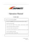
1
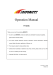
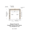
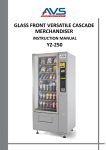
FY operation manual Operation Manual 6250LQ Thank you very much for purchasing INFINITI In order to use INFINITI correctly and safely and understand this product’s capability, please read this manual carefully. The manual includes equipment structure, description, technical parameters, operation manual, safety information, application of software, etc. Subject to change without notice. We tried our best to edit this manual and test our machine before market; however, we do not guaranty errors existing. Please inform us if you find any. All copyrights are reserved. Any violation to the copyright may cause lawsuit. Version 1.5 September 25, 2003 -1- FY operation manual INDEX CHAPTER 1 1.1" 1.2" 1.3" 1.4" 1.5" SAFETY INFORMATION Important Safety Information Caution When Using Printer Guidance When Using Ink Container Choosing Printer Installation Place Caution, Warning, and Attention CHAPTER 2 TECHNICAL SPECIFICATION CHAPTER 3 3.1" 3.2" 3.3" EQUIPMENT ASSEMBLY AND ADJUSTMENT Assemble Digital Printer Adjust Digital Printer Cautions before Turn on INFINITI 6250LQ CHAPTER 4 EQUIPMENT STRUCTURE AND ACCESSORIES CHAPTER 5 5.1" 5.2" 5.3" PANEL BASIC OPERATION Menu Structure of Control Panel Function Description in Detail Printing Steps CHAPTER 6 INK SUPPLY、CLEANING SYSTEM AND DESCRIPTION FOR MULTI-FUNCTION AUXILIARY BOARD CHAPTER 7 7.1" 7.2" 7.3 7.4 7.5 7.6 INK SUPPLY SYSTEM Summary System Diagram Function Description Operation Description Intelligent Detection Function Intellectualized Manual Button CHAPTER 8 8.1" 8.2" 8.3" CLEANING SYSTEM Summary System Diagram Operation Description CHAPTER 9 9.1" 9.2" 9.3" 9.4" HEATING SYSTEM Summary System Diagram Function Description Working processing and character CHAPTER 10 10.1" 10.2" 10.3" SOFTWARE OPERATION Installation Usage of software Operation of RIP CHAPTER 11 11.1" 11.2" 11.3" 11.4" MAINTENANCE GUIDE Preparation for the printer Prepare software Adjustment Maintenance for print head -2- FY operation manual Chapter 1 SAFETY INFORMATION 1.1" Important Safety Information Before using your INFINITY FY6250LQ InkJet Digital Printer, Please read following safety information. Pay attention to the cautions on the Printer. • Don’t block the hole on the cover. • Don’t insert any object into the Printer groove. Don’t let any kind of moistures splash into Printer. • Only use the Power Supply according to the label. You may choose either AC 110V or 220V for different countries and regions. • Please make sure the connection is correct for the Power Supply Cable before turning on the Printer • Avoid to use the Socket controlled by the switch on the wall or by auto timing controller • Please keep Printer away from the Magnet Interaction, For example: Speaker and Mobil-phone • Don’t use damaged Electrical Power wire • Don’t try to repair Printer by yourself • Contact your Local Service Center to repair, if the following situations occur: Power wire or Socket damaged Liquid splashes into Printer Printer damaged and Cover broken Printer can’t work properly or printing quality has conspicuous change 1.2" Caution When Using Printer • Don’t use your hand to move print head; otherwise the Printer will be damaged. • Always use power switch to Turn On/Off the Printer. Before Shutting down the Printer, do not pull out Power Supply wire or Data Wire. • Before moving the Printer, please make sure the Print head at Original position and firmed. 1.3" Guidance When Using Ink Container • Keep ink container away from children. Don’t drink or touch. • If ink spills on the skin, please wash with soap and water. If ink splashes into eye, please wash with water immediately • Don’t shake the ink container, which causes ink leak. • After three months, you should take off the ink container, clean it and dry it. • Please keep surrounding clean when you replace a new ink container. It helps you improve printing quality. 1.4" Choosing Printer Installation Place • Make sure to leave enough space for the Printer; otherwise, the Printer may not work properly. • Don’t leave Printer at a place where temperature and humidity change severely. Avoid sunshine, strong light and heat. • Avoid shaking and vibration. • Keep sufficient room for air circulation. • Place Printer nearby the Power socket, so it is easy to connect or disconnect the Power Supply -3- FY operation manual 1.5" Caution, Warning and Attention Caution Must obey in order to ensure person’s safety. Warning Must obey in order to protect the machine. Attention It includes the important and useful information about operation. -4- FY operation manual Chapter 2 TECHNICAL SPECIFICATION Figure2-1 Outlook Production Type INFINITI Serials:6250LQ Print technique 6250LQ:SPECTRA SL-128 piezo head, 4 heads inside Resolution 180dpi、270dpi、360dpi、540dpi、720dpi Pattern quality Photo effect (basic, high quality) Media width 2530mm Max printing width 2520mm Display LCD display with 8 key panels Ink type Solvent-base:C, M, Y, K Ink supply 300ml/min auto flow pump ink supply,volume of main tank 800ml/color Ink inspection system Auto/manual ink supply, ink low detector Printing software Support RIP drives for Window98、2000、XP etc Media type Normal PVC banner, vinyl, coating film, polyester, etc. Media transfer Roller paper of sheet (size bigger than A4 or 210mm) Media feeding system Auto feeding and take-up units weight less than 40kg/roll Print head height Adjustable distance between 2mm-4mm to media Heating system Front-rear temperature control, two-digit LED display, adjustable 30°C-60°C Clamp Manual adjust media width -5- FY operation manual Print head cleaning system Auto cleaning device with anti-clogged flash function and auto adjustable purging setup Safety system Inside safety lock with function or shut down system Printing interface High speed data transport PCI card Print Language HH-RTL printing language Noise Printing status≤ 60dB/waiting status≤ 40dB (ISO7779) Printer-size ( including box)/net weight ink Size: Length × Width × Height 3600 mm×870 mm×1270 mm / 305kg Package size/weight 3720 mm×890 mm×1100 mm/368KG Input Voltage AC 100 - 240 V, 50HZ/60HZ (Heating voltage can be set up by an engineer inside machine; control power supply is automatically set up) Voltage for the feeding and the cleaning system AC 220V, 50HZ/60HZ(optional: AC 110V) Power ( when AC 220V applied) Control:≤ 3A Heating:≤ 5A Feeding、cleaning:≤ 5A Software platform Window98、2000、XP Working environment Temperature:20°C - 28°C Subject to change without notice. -6- FY operation manual Chapter 3 EQUIPMENT ASSEMBLY AND ADJUSTMENT 3.1 Assemble Digital Printer Screw detachment Screw detachment Figure 3-1 Packing screw’s detachment Print head fixation screw detachment Screw installation Screw installation Ink tank Figure 3-2 Screw installation and print head fixation screw detachment 1. According to the Pattern above, please assemble kickstand by following step: feet with truckle, kickstand, and ink supply box. 2. Please tighten all Screws on the Feet; prepare to assemble the Core Part. 3. Please confirm carrying on assemble project with sufficient workmates, and then tighten all screws with core part. Confirm no shaking occurs. 4. Install ink supply system on right side. 5. Please connect all data wire and power wire correctly. 3.2 Adjust Digital Printer 1. Make sure all data wire and power wire connected correct, and then Turn on your Printer. 2. Put media on the roll behind the Printer or insert single sheet paper on the printing table. Clamp the pole on the right of Printer. The Printer detects the media width automatically. -7- FY operation manual 3.3 Cautions before turn on INFINITI 6250LQ 1. In order to make print head clean easily, please be equipped with: • Chemical reagent: CH3COCH2CH3. • Cleanroom wiper. 2. In order to inspect temperature and humidity for working surroundings, please prepare measure instruments/gauges with measurement functions of humidity and temperature. Requirement for environment: • Temperature: 20°C - 28°C • Humidity: 40% - 70% 3. Power supply standard • You may select AC 110V or 220V for different countries or regions. • Control power supply: AC 100 - 240V 50/60HZ • Heating power supply: AC 100 - 240V 50/60HZ • Take up power supply: AC 100 / 240V 50/60HZ (optional: AC 100 V) • Cleaning power supply: AC 100 / 240V 50/60HZ (optional: AC 100 V) • Ground wire must be well connected for Printer. Be equipped a UPS regulated power supply for better solution. 4. Requirement for computer In order to avoid problems caused by computer, please choose high quality computer or brand computer such as DELL or IBM, etc. -8- FY operation manual Chapter 4 EQUIPMENT STRUCTURE AND ACCESSORIES 10 3 12 11 2 18 31 Figure 4-1 INFINITI 6250LQ (Front) 6 7 3 1 10 5 4 2 24 25 31 26 Figure 4-2 INFINITI 6250LQ (Front) -9- FY operation manual 20 21 23 19 22 14 28 29 27 Figure 4-3 INFINITI 6250LQ (Back) 15 16 18 Figure 4-4 INFINITI 6250LQ (Back) 6 17 13 Figure 4-5 INFINITI (Partial) - 10 - FY operation manual 10 10 29 31 28 30 27 Figure 4-6 INFINITI 6250LQ 1. Print Head:4 piezo print heads for INFINITI 6250LQ 2. Printing media: 3. Printing board: 4. Power Switch:Turn on/off Printer 5. Clamp Pole:Control roller up / down for loading or unloading media 6. Press Roller:Corporate with rubble feed roller and make media move smoothly 7. LCD Control Panel:To set up parameter, execute all function and changing printing mode 8. Multi-function Auxiliary Board 9. Clamp:Manually adjust media width and keep media move straight 10. Heating board: 11. Frame:Support the machine 12. Side Cover:There are two side covers on left and right sides 13. Waste Ink Trough:Use to collect the waste ink - 11 - FY operation manual 14. Main Waste Ink Bottle:Use to collect the waste ink 15. Vacuum: 16. Vacuum Power Socket: 17. Suck Mouth: 18. Waste Ink Bottle:Use to collect the waste ink from suck mouth 19. Main ink tank and cleaning solution tank:a total five lines, including C, M, Y, K and solvent flushing, 800ml/each 20. Printing Interface Socket:Connect to Data card on computer 21. Power Socket:Provide power for Printer 22. Heater Power Socket:Provide power for Heater 23. Heater corona protection switch:For heater corona protection 24. Take-up/Down feed Media Power Switch: 25. Take-up Media control power:To control the media rolling forward or backward 26. Down feed Media control power:To control the media rolling forward or backward 27. Down feed Media support roller: 28. Down Feed Media Roller:Pull media out 29. Down Feed Media Press Roller:Increase the power when pulling media out 30. Take-up Media Press Roller: To ensure media tension all the same, a fixed pressure should be given to media when taking up. Alternatively, you may put a light pole on 31. Take-up Media Roller: Used to take up media - 12 - FY operation manual Chapter 5 PANEL BASIC OPERATION 5.1 Menu Structure of Control Panel LCD Direction Key Function Key Figure 5-1 Control Panel Function Keys 1. Direction (Arrow) Key 2. Function Key 1) ONLINE:Use to switch between online mode and offline mode; press down for 3-4 seconds to pause a printing task 2) ESC:Back to the upper menu 3) ENTER:Confirm the menu command and execute it 4) FUNC:Operation key--press FUNC key, Printer is on self test mode when offline; Press FUNC key, print head move to left side when it is on Clean Pos mode 3. Basic Operation After turning on, Printer starts self-test automatically, including X motor test and Y motor test. Once finishing the self-test, print head go back to the original position. You will see the following information displayed on the LCD screen: • Mark /// INFINITI with machine model • Version • Then back to basic operation menu. The machine is on a normal track, as shown below. - 13 - FY operation manual MENU OFFLINE CH6250LQ 1. Moving System + 2. Clean Tools + 3. Adjustment + 4. Options + Figure 5-2 Main Menu Sign + stands for submenu followed. Sign – stands for no submenu followed. In this case, press / key of the arrow keys can circularly display these four menus up and down. When there’s a sign “+” after the menu arrow (that is the first line on menu), press ENTER key, and submenu will be displayed. For example, when the arrow point to “1.Moving system”, press ENTER key, it will display on the LCD screen as follows: MENU → M1 OFFINE 1.X-MOVE - 2.Media Detect - 3.Clean Pos - 4.Print Pos M1 stands for the submenu of the first main menu - In this case, press ESC key, it will go back to main menu. Press / key of the arrow keys can circularly display these four menus up and down. When there’s a sign “–” after the menu arrow (that is the first line on menu), press ENTER key to execute operation. Press ESC key to exit operation. 5.2 Function Description in Detail Dendritic structure of menu: Moving System MENU OFFINE Clean Tools Adjustment Options 5.2.1" Moving System MENU M1 OFFINE X - Move Media Detect Clean Pos Print Pos - 14 - FY operation manual 1. X-Move Press ENTER key, Move flashes on and off on the LCD screen. Press / key of the arrow keys can cause media move back and forth. Press ENTER key to confirm when move to the right location. Y-Move Press ENTER key, number XXXX flashes on and off on the LCD screen. Press / key of the arrow keys can cause print head move right-and-left. Press ENTER key to confirm operation. 2. Media Detect Press ENTER key, print heads move on Y direction back and forth once to check a media, and then it stops at original position. If “ERROR” displays on the LCD screen, you probably have neither a media nor detect sensor installed (It is not available when the manual published). 3. Clean Position Press ENTER key, number XXXX flashes on and off on the LCD screen. Press / key, print heads move right-and-left. Commonly, set the clean position on left edge. Then press ENTER key to save the information. When you want to clean the print head and pump ink to ensure no nozzle-clogging, you can use this function. After enters this function, number XXXX flashes on and off on the LCD screen. Press FUNC key, print head will move to the defined cleaning position. Press pressure automatically; Press 4. key, start to clean with negative key, start to purge once. Print Position Press ENTER key, number XXXX flashes on and off on the LCD screen. Press / key, print heads move right-and-left. Set up a value as a start printing position, press ENTER key to save the information. When you print an image or print test drawing, they start at this position. 5.2.2 Clean Tools Clean All MENU M2 OFFINE Purge Ⅱ Purge Ⅲ 1. Clean All Press ENTER key, print heads move to Clean Position and ink sprays automatically with negative pressure. 2. Purge Ⅱ Press ENTER key, jet flashes on and off on the LCD screen. Print head sprays ink automatically to prevent the nozzles clogging. Flashing will automatically disappear after the completion of the operation. Press the ENTER key again, and print head will spray ink again. In this mode, ink amount is medium. 3. Purge Ⅲ Press ENTER key, jet flashes on and off on the LCD screen. Print head sprays ink automatically to prevent the nozzles clogging. Flashing will automatically disappear after the completion of the operation. Press ENTER key again, and print head will spray ink again. In this mode, ink amount is more than Purge II. Purge Quantity from Options can set the ink amount. - 15 - FY operation manual 4. Jam Test Press ENTER key, device will print test draw directly. It is the same when pressing FUNC key in Offline mode. 5.2.3 Adjustment Moving Test MENU M3 Print Speed BID Adjust OFFINE Rectangle 1. Moving Test Press ENTER key, the LCD displays as below: MENU → M3-1 Moving Test Press <FUNC> to run Test and Press Execute it follow by hints on screen. In this case, device is in a simulative plotting status. Print head will not spray ink. <ESC> to stop 2. Speed Moving speed on Y direction, range from 1 to 15. Maximum is 15, however, the printing quality will go down if 15 selected. Our suggestion is level 10 or lower, do not over 13. 3. BID adjust MENU → M3-3 BIG Adjust XXXX This function is used to adjust print head and avoid the image dislocation when bi-directional printing Press <FUNC> to run Test Print Refer to the software INFINITI 6250LQ (TRY) for details. Set up a speed at level 4 for best result. Note: An engineer usually completes it. Customers do not need adjust it by themselves. 4. Rectangle Feed compensation. This function is used to adjust the feed compensation on media moving direction (X-Direction). Note: This function does not work for new models with spectra. An engineer usually completes it. Customers do not need to adjust it by themselves. - 16 - FY operation manual 5.2.4 Options Purge Times MENU M4 Purge Quantity Paper Detect OFFINE Fan Velocity 1. Purge times Set up number of lines, print head will clean with negative pressure automatically after reaching the number. No purge applied if setting is “0”. 2. Purge Quantity Set up the amount of ink sprayed after cleaning print head. The ink amount also applied to the Purge III when cleaning print head manually by M2 3. Paper detect Used to detect media border before printing. Option is 0 or 1. “0” stands for no paper detect. “1” stands for paper detect automatically. This function has not implemented yet, set up “0” until further notice. 4. Fan velocity Used to set suction for media. Range is 0 – 255, normally, setting is 128. 5.3 Printing Steps Normally, you can operate by the followings: 1. Take off the print head cap. 2. Turn on air valve. 3. Insert media smoothly. Lower the clamp lever. 4. Turn on the power switch of printer. 5. Press F2 on MFAB, clean the heads and print test draw until there is no nozzle clogged. 6. Press the ONLINE key to select an ONLINE mode. In the case ONLINE MODE display on the LCD screen. 1. Moving System + MENU OFFLINE 2. Clean Tools + 3. Adjustment + 4. Options + ONLINE MODE Figure: Online Mode Figure: Offline Mode To switch between online mode and offline mode, press ONLINE key. On offline mode, the LCD displays operation menu. On online mode, the device will receive printing data from computer and execute output operation. 7. After processing the pattern you want to print out, copy the image to the control computer. 8. Use RIP software to print. See Chapter 10 for details. - 17 - FY operation manual 9. When printing, the LCD displays as bellows: Total lines of printing task PRINT PROJECT Lines were done LINE: TOTAL: XXXX FINSH: XXXX Lines RIP ready RIP READY: XXXX Figure: Interface of Printing Total lines of printing task, the lines were done and the lines RIP ready are shown on LCD screen. 10. If the nozzles are clogged during printing, press ONLINE key for three-second for a pause (it is applied when print head is at original position), then clean the print head. After cleaning up, press ONLINE key again to continue the operation. Operation steps for cleaning as follows: To avoid the nozzles clogging while printing, you can press ONLINE key to pause. Press key, let the print head move to leftmost and do the cleaning operation by selecting F2 on MFAB. Press print head will spray ink downward automatically; Press key, the key, the print head execute F2 cleaning and negative pressure cleaning. When finishing, press ENTER key to continue printing. Press key to let the print head move to original position. Press ESC key to cancel the printing operation. Do not switch mode from ONLINE to OFFLINE until “printing cancel” shows up on computer. 11. After printing, press ONLINE key to set the printer to offline mode. - 18 - FY operation manual Chapter 6 INK SUPPLY、CLEANING SYSTEM AND DESCRIPTION FOR MULTI-FUNCTION AUXILIARY BOARD 6.1" Ink Supply and Cleaning System 1 2 3 4 5 Figure 6-1 Ink Supply and Cleaning System(Right) 1. Main ink tank C 2. Main ink tank M 3. Main ink tank Y 4. Main ink tank K 5. Main ink tank F 1 7 8 2 9 3 10 4 11 5 6 12 13 14 Figure 6-2 Ink Supply and Cleaning System(Back) 1. Ink pump C 2. Ink pump M 3. Ink pump F 4. Ink pump Y 5. Ink pump K 6. Air pump 7. Air filter 8. Solenoid valve - 19 - 9. Ink filter C FY operation manual 10. Ink filter M 11. Ink filter F 12. Ink filter K 13. Ink filter Y 14. Governor valve Governor valve: used to control air pressure. Increase the pressure when fixed; Decrease the pressure when loose. 7 8 6 1 2 3 4 5 Figure 6-3 Ink Supply and Cleaning System(Back) 1. Sub tank C 2. Sub tank M 3. Safety tank 6. Floating switch (inside of sub tanks) 4. Sub tank Y 7. Tube for out coming ink 5. Sub tank K 8. Tube for incoming ink 9 1 2 6 7 3 8 4 5 Figure 6-4 Ink Supply and Cleaning System(Back) 1、Cyan 2、Magenta 3、Yellow 4、Black 5、Cleaning Solution - 20 - 6、Air Pump 7、M Connector FY operation manual 8、F Connector 9、Tube Cap Incoming Ink Print head Figure 6-5 Ink Supply and Cleaning System(Front) 4、Handle 1、M End 2、F End Figure 6-6 Air Valve Air Valve: 1、M End(Input):Air input 2、F End(Output):Air output 3、F End (sealed):Sealed by tube cap 4、Handle:Handle’s direction means the line closed Valve Position: - 21 - 3、F End (sealed) FY operation manual During a normal operation process, open valve, the handle point to Position 3;After printing task, put valve on position 2. Tube Connector: Channel connected by M tube connector and F tube connector. Tube Cap:to seal a channel. 6.2 Multi-function Auxiliary Board and Description Multi-function Auxiliary Board (MFAB) has many functions. It can control ink supply, cleaning and heating. Function Keys described below: 7 8 9 10 11 12 13 6 Actual Temperature 5 Set Temperature 1 K1 2 K2 3 K3 4 K4 Figure 6-3 Multi-function Auxiliary Board 1、K1 Function Key,used to select any functions, including: F1:out of Manu,back to Temperature display F2:AP,start Air Pump(Low) F3:AP,start Air Pump(Medium) F4:AP,start Air Pump(High) F5:TF,set up temperature for front heater,30℃~60℃ adjustable F6:TR,set up temperature difference between rear heater and front heater, 0℃~8℃ adjustable (temperature in the rear is lower than the front). - 22 - FY operation manual 2、K2 To adjust temperature. 0℃~9℃ is adjustable, when F5 and F6 are applied. 3、K3 To display the two temperatures alternative and adjust the values. 10℃ adjustable when press this key once. 4、K4 Confirmation Key Attention:K2+K3:Press K2 and K3 will display FC FP. Then press K4 to confirm, Cleaning Pumpwill start. 5、Digital Display Used to display temperature setting; It can be display name of function if F1 is applied; Display Er when error occurs. 6、Digital Display Used to display actual temperature; It can be display name of function if F1 is applied; Display error code when error occurs. Er01, Er02, Er03, Er04 indicates lacking of ink for sub-tank of C, M, Y, K respectively; Er05, Er06 indicates that one of the two wasted bottles is full respectively; Er07 indicates that the safety bottle is full. 7、Socket Connect to Ink Pump for Cyan, marked as blue. 8、Socket Connect to Ink Pump for Magenta, marked as red. 9、Socket Connect to Ink Pump for Yellow, marked as yellow. 10、Socket Connect to Ink Pump for Black, marked as black. 11、Socket Connect to Cleaning Pump, marked as transparence. 12、Socket Connect to Air Pump, marked as white. 13、Socket Connect to Tee solenoid valve, no mark. - 23 - FY operation manual Chapter 7 INK SUPPLY SYSTEM 7.1 Summary This ink supply system provides automatic and manual supply functions. It can control several lines of pump supply ink at the same time. It has perfect interface. It also can adjust ink supply pressure and provides protect function. 7.2 System Diagram Ink Control Supply Sub-ink Tank Print head Floating Switch Filter Ink Control Board Pump Output: Input: Speaker Signal for floating switch Pump light Interface signal Ink light Manual ink supply Main Tank Power Supply Figure7-1 System Diagram for Ink Supply 7.3 Function Description 1. This system can supply several lines automatically at same time. 2. With standard alarm and protect function. If any line of ink supply system is abnormal, alarm will occur and point out which line is abnormal. The others still work. 3. It is easy to communicate with other system. All floating switch sensor signals can be input by serial port or parallel port. 4. Main control consists of micro CPU, all detect signals use software intelligence signal detect program to achieve reliability. 5. To prevent ink supply problem caused by electric circuit, main control set pump act limit time intelligently by restricting maximum amount ink. 7.4 Operation Description Note: please read descriptions carefully for Ink supply system, clean supply system and Ink Control system before starting the following operations. - 24 - FY operation manual 1. Preset ink supply interface and ink supply pressure setting. 2. As soon as the printer’s power on, system will detect floating switch signal automatically. 3. When a line lacks of ink, system starts ink pump and corresponding indicator light will turns on. After the ink level is the setting value, ink pump will work for a while and then stop. 4. When ink in main ink tank lacks or any other abnormal situation occurs, the ink pump will run out of the limit time and the system force the pump stop, meanwhile, alarming occurs and corresponding indicator light turns on. Press the K4 on MFAB to reset, the light turns off, and system goes back to normal process. K4 Figure 7-2 Multi-function Auxiliary Boards 7.5 Intelligent Detection Function Intelligent detection function for ink supply system is implemented by collecting signal with high frequency floating switch. By using concept of probability, we think the signal is useful if a signal of floating switch is greater than a setting value (for example, 80%). Therefore, this reduces mistakes by floating switch and improves ability for anti-interfere. 7.6 Intellectualized Manual Button System will automatically reach a setting ink level when you press the manual button once. - 25 - FY operation manual Chapter 8 CLEANING SYSTEM 8.1 Summary There are three cleaning methods: cleaning by positive air pressure, cleaning by cleaning solution and cleaning by negative air pressure. You have choices of Auto Cleaning and Semi-auto Cleaning, in the following circumstances: before printing, during printing and in a certain period for idle. 8.2 System Diagram Ink Air Filter Tee Valve Safety Control Ink Tank Board Ink Filter Print Head Floating Switch Multi-function Auxiliary Board Air Reducing Valve Output: Air Filter Input: Pump light Data Signal Cleaning Solution Light Air Pump Liquid Valve Air Valve Signal Main Tank/Clean Solution Tank Power Supply Figure 8-1 Diagram for Cleaning System 8.3 Operation Description 1、 Cleaning for Printer at first time When using printer at the first time, you must clean all the special moisture filled in print head, which prevent print head clogged during transportation. The moisture does not dissolve in ink. You may fill ink into print head unless the moisture cleaned up completely. First, fill ink and cleaning solution into Main Tank and Cleaning Solution Tank respectively, and then turn on printer after checking all cables connected correctly. System will automatically fill ink into sub tank until full. To clean up the special moisture from ink lines, you may do it one print head each time: • Move print head to Clean Position - 26 - FY operation manual • Open a cap on sub-tank of cleaning solution (F) • Connect tube F to tube M (C, M, Y, K line) respectively • Press K2 and K3 synchronously, after confirming by K4, cleaning solution comes out from print head(s) • Repeat steps above, until the cleaning solution is out straightly from each print head. Caution: After cleaning up all the moisture for each print head, you need put all the lines back to original position, meanwhile, seal the line of cleaning solution. Ready to pump ink into print head: Press K1 on MFAB, select F4, after confirming by K4, ink comes out from all print heads 2、 Before printing - Cleaning with Positive Pressure K1 Figure 8-2 Operation Key Move print head to Clean Position, Press K1 on MFAB, select F2: ① Ink fill in each print head and the line, since Air pump forces air into ink sub-tank, by positive pressure. ② Three options for air pressure level: F2—Low;F3—Medium; F4—High. Note: normally, do not use F4, since it’s ink consuming. 3、 During printing - Cleaning with Positive Pressure If any print head clogged during printing, you need cancel the task and do the cleaning. Operation is the same as 2 above. 4、 Printer idle for a long time - Cleaning with cleaning solution If Printer idles for a long time, you need clean print head with cleaning solution before turning off Printer. It is better to inject a special moisture into print heads to keep the heads’ lifetime longer. - 27 - FY operation manual Before cleaning print heads: • Move print head to Clean Position • Open a cap on sub-tank of cleaning solution (F) • Connect tube F to one of tube M (C, M, Y, K line) Then: ① Press K2 and K3 synchronously, after confirming by K4, then cleaning pump starts to work. ② Force ink out of print heads and lines with cleaning solution. ③ Change to another line if one print head and the line cleaned up. - 28 - FY operation manual Chapter 9 HEATING SYSTEM 9.1 Summary This heating system can adjust its temperature based on different PVC material and surrounding. It can adjust the temperature automatically to match a setting temperature. Customer can have satisfied printing effect. 9.2 System Diagram Temperature adjust switch Heating Light 1 Driver Heating signal 1 SCM Heating driver temperature signal Front heater DIP1: Temperature setting Light 2 Heating Driver Heating signal 2 Heat-control board Back heater Control Board Operation Board 110V or 220V Temperature adjust switch Figure 9-1 System Diagram for Heating System 9.3 Function Description 1、It can control the two front and back lines’ heating board auto constant temperature at same time. 2、 With advance protective functions for over heating, short circuit, etc. The line will shut down automatically if a certain line’s temperature is over 75° C. After the temperature cool down, it will resume. Over heating will not happen even if the entire input signal turned off. 3、 The system can work independently and can be easily transportable. It is easy to convert input voltage from AC110V to 220V. 4、 Based on different medial and surrounding, customers can easily adjust temperature by the function key F5 on the operation board. 5、 The heating system is controlled by advanced intelligent microprocessor; it has characters of heating up quickly, temperature controlled accurately and saving energy. - 29 - FY operation manual 6、An inner heating board is used. It is easy to install, no extra space needed and longer life warranty. 9.4 Working processing and characteristics 1. To set up basic temperature (30℃~60℃) by function key F5 on operation board. Temperature difference (0℃~8℃) between the front and the rear can be set up by function key F6 on operation board. 2. Heating power supply is separate from control power supply. Please turn on the heating power before turn on the power for the printer. Once the power is on, the system heats up automatically to setting temperature and keeps the temperature at the setting value. Without turning on power for printer, the heating system will not work, however, there is still AC 220V inside machine. 3. Temperature detect lies on the right side of physical printing start position about 50cm. Print media should cover this region when printing. 4. After work, must turn off the two power supplies. - 30 - FY operation manual Chapter 10 SOFTWARE OPERATION 10.1 Installation 1. Installation of Feiyeung RIP Software: see the RIP User’s Manual for details. a) Insert RIP CD into computer b) Run setup.exe c) Follow the instruction to finish the installation 2. Installation of printer driver a) Insert FY CD into computer b) Run setup.exe under directory of TRY SETUP c) Follow the instruction to finish the installation Note:Please use the default directory for the installation. 3. Installation for corresponding files Copy necessary files to computer, including the followings: 10.2" • Curve of Ink Viscosity • Curve of Voltage • Curve of Linearization • Curve of Color Tune Usage of software Note:This software is the driver for Printer FY serial and used to adjust the print head by engineer. Operators do not need use it. 10.2.1 1. Open the TRY Select start \programs\Try - 31 - FY operation manual Figure 10-2-1 Open Try 2. Open Try,the interface show as below: Figure 10-2-2 Try interface 3. Select printer type first: please select 6320LQ on the printer Menu; see below: - 32 - FY operation manual Figure 10-2-3 Select printer types 4. Open File, set up print parameters, see figure below: Figure 10-2-4 10.2.2" Set up print parameters Figure 10-2-5 Set up print parameters This function used to set up printing parameters, select printing mode, unidirection or bidirection printing - 33 - FY operation manual and amount of ink. Note:normally, select four colors; select one of colors to print only by engineer. 1. Set up print parameters Press “More”, the following warning shows up: Figure 10-2-6 Warning Message Press “Yes” to confirm, a dialog box for setting up parameters pops up as below: Figure 10-2-7 6250LQ Setting dialog box Distance coefficient for a print head expresses as below: Y Direction(360DPI) :Yc=0 C is basis Ym=496 Distance between M and C Yy=992 Distance between Y and C Yk=1488 Distance between K and C X Direction (1080DPI) :in theory,four-head is at the same level on X direction. Therefore, the - 34 - FY operation manual default value is 0. Note: Please press Download first to download original data of the machine before making any changes. 1) Introduction of head install parameter Head install parameter:used to adjust the gradient of print head 360DPI:printing resolution of Y direction, e.g. horizon direction 1080DPI:maximum printing resolution of X direction, e.g. media feeding direction X Direction(Media feeding direction) Xc=0 Xm=0 Yc=0 Ym Xy=0 Xk=0 Yy Yk C Y Direction(Horizontal Direction) M Y K Figure 10-2-8 Diagram for installation of print head(View on Back of Printer) 2) Adjustment for print head install parameter • Y direction a) Back to Figure 10-2-2,Open the testing file named overlap-360.group,see Figure 10-2-9: Figure 10-2-9 Testing image for Y direction b) Open “Print Setup”, select four colors with “Test Mode” for Print Mode c) Press“ ” to print d) Check the print swatch, if four colors overlap together, the line with value of 0 is straight; otherwise, adjust the parameters according to the values for straight lines. • X direction - 35 - FY operation manual a) Back to Figure 10-2-2,Open the testing file named overlap-1080.group,see Figure 10-2-10: Figure 10-2-10 Testing image for X direction b) Open “Print Setup”, select four colors with “360x540 1 PASS” Print Mode c) Press“ ” to print d) Check the print swatch, if four colors overlap together, the line with value of 0 is straight; otherwise, adjust the parameters according to the values for straight lines. After finishing the adjustment, press “Upload” to save all parameters to Printer. 3) Ignore X parameters and Ignore Y parameters Those functions only used by engineer for testing and maintenance. Normally, users do not need them. 2、Bidirction compensate In order to prevent image from mis-position when bidirection selected, use this function to adjust print head. The result for Birdirection compensate is different from one to another depends on a setting of Speed. Operation steps: 1) Set up Adjustment\Speed (< = 13) on Menu M3-3 on the Operation Control Panel for 6250LQ. 2) Set up Adjustment\Bid Adjust to 0 on Menu M3-3 on the Operation Control Panel for 6250LQ. Press “ENTER” to confirm, then Press “ONLINE”, Printer is in Online mode. 3) From Try software for 6320LQ, open testing file BID.group. - 36 - FY operation manual Figure10-2-11 Bidirection compensate image 4) Press“ ” button, print the bidirection compensate image. 5) Check the image to find a straight line. Reset the values on Adjustment \ Bid adjust according to the data above the line. 6) Follow the same steps above, get Bidirection compensate results at different speed setting. 3、Feed compensate There are different feed compensate results for different pass number you selected. To compensate feeding on Y direction, following by: 1) Select 360x180 1Pass,Adjustment\Rectangle on operation control board is not available for 6250LQ. Press ONLINE make printer Online Mode. 2) In 6320LQ Try,open testing file named 180.group Figure 10-2-12 Feeding compensation image (180.group) 3) Press“ ” button,start to print 4) Check the swatch, see if the lines are even (better check by microscope); if not, back to Figure 10-2-7 to adjust parameters until all lines are even, then click on “OK”. 5) When select 360x270 1Pass,open 270.group, following the rules above to reset the parameters, and then click on “OK”. 6) Step1 to 4 can be applied for different pass settings. 4、Print head voltage curve Press“ Voltage Curve” button, pop up a dialog box as below: - 37 - FY operation manual Figure 10-2-12 Dialog box for setup print head voltage 1) Load Ink Viscosity Curve: Press “Viscosity File” button, select spectral.ink for FY6250LQ. The curve shows relationships between ink viscosity and temperature. 2) Load Voltage Control Curve: Press “Read Curve” button, select spectra.crv for FY6250LQ. The curve shows relationships between voltage and temperature. 3) Save voltage control file:After finishing adjustment voltage for each print head, press “Save Curve” to save the Voltage control file 4) Voltage control: Used to control and adjust a voltage for each head 5) Temperature control: Used to control and adjust a temperature for each head 6) Upload: Save all updating data from computer to Printer 7) Download: Read all data from Printer to computer To user: • If you change a computer for Printer, you need download all the print head data from Printer to computer before starting to print, which includes Ink Viscosity Curve, Voltage Curve and voltage values, etc. • To download all data from Printer to computer, select “ALL” and press “Download” button. Note: user may choose different Ink Viscosity Curve and Voltage Curve according to different inks used. - 38 - FY operation manual Setup voltage value: There is a Calibrated Voltage for each head from manufacture. The value is gauged under standard surrounding. However, the voltage is difference between standard and actual working surrounding. Usually, you need setup a voltage lower (10% - 15%) than a calibrated voltage for better printing quality. For example, if Calibrated Voltage is 100V, you may setup voltage value between 85V and 90V. If a voltage is higher than the Calibrated Voltage, there are spots and out of ink easily when printing; if a voltage is too low, the line is not straight and ink is less than regular amount when printing. Try to find an ideal voltage by the adjustments. There are two ways to do the adjustment: • Adjust voltage for each print head individually • Or adjust voltages for all print heads by adjusting voltage coefficient or additional voltage. To increase voltage, select voltage coefficient > 1, vice versa. If additional voltage > 0, increase voltage; if additional voltage < 0, decrease voltage. There is 0.5V difference when increasing or decreasing 1 for the additional voltage. Warning:For regular user, please Do Not change value of voltage, otherwise, printing quality will not be guaranteed. 10.3 RIP Operation Please refer to “RIP User’s Manual” for detail. Close the Try first, then open RIP program. 1、 Click Feiyeung RIP icon to open program 2、 Registration of the RIP Select “ Registry” from menu of Help, a dialog box pops up: Figure 10-3-1 Dialog box for registration Fill out registration number, which saved on CD directory “registration number”. It is case sensitive. Note:register at the first time only. 3、 Create new file 4、 Import image 5、 Adjust size, position for the image 6、 Print - 39 - FY operation manual 1) Select “File” / “Print”, pop up a dialog box, see below: Figure 10-3-2 Dialog box for printing 2) Press “Modify” button, a dialog box shows below. Set up corresponding parameters. Figure 10-3-3 Setup print parameters 3) Press “Setting” button, set up the parameter according to the fields. - 40 - FY operation manual Figure 10-3-4 Large page devices 4) Press “Property”, a dialog box shows below: Figure 10-3-5 Set up print parameter a. Select corresponding resolution. Print Mode is the same as 6320LQ in RIP, including 8 modes: 360×180 1Pass,360×180 2-1Pass,360×270 1Pass,360×270 2-1Pass, 360×360 1Pass,360×360 2-1Pass,360×540 1Pass,360×540 2-1Pass Meaning: • 360×180 1Pass:Print resolution on Y direction is 360dpi; Print resolution on X direction is 180dpi, only print once at the same position for an image. - 41 - FY operation manual • 360×180 2-1Pass:Print resolution on Y direction is 360dpi; Print resolution on X direction is 180dpi, but it divided into two times to print. The amount of ink used is as much as 360 x 180 1Pass, it has better printing quality, but the speed is half of 360 x 180 1Pass. • 360×360 1Pass:Print resolutions on Y direction and X direction both are 360dpi, the amount of ink used is double of 360 x 180 1Pass. • The same principle is applied for the rest modes. b. Select unidirection or bidirection. Bidirectional printing is more efficient than unidirection’s. 5) In Figure 10-3-3, press “Calibration”, install corresponding curves. Figure 10-3-6 Set up advanced parameters 6) In Figure 10-3-2, press “Print” button to print See “ RIP User’s Manual” for more functions and descriptions. Note: If you want to cancel a task during printing, you may use the RIP software to do so. If you prefer to cancel a task on Printer, you need wait until “Printing Cancel” displays on Menu (Printer now is on Offline Mode). - 42 - FY operation manual Chapter 11 MAINTENANCE GUIDE 11.1 Preparation for the printer 1. Printer installation and power connection 2. Data cable installation and connection • Plug in the data card (INFINITI Fast SCSI II Adapter Card) to socket of PCI on computer • Connect the data card to COM on computer by a serial cable • Connect Printer to the data card by corresponding cables. 3. Cleaning for Ink Supply System and Print head See 8.3.1 for details 11.2 Prepare software 1. Installation of Feiyeung RIP Software 2. Installation of printer driver 3. Installation of curves 4. Registration of the RIP 5. Loading important curves and data from the RIP software In order to print with better quality, you need install the following Spectra curves to right places: • Curve of Ink Viscosity • Curve of Voltage • Curve of Linearization • Curve of Color Tune After installation, you have to download a labeled voltage from Printer for each print head ; otherwise, printer will not work or print with bad quality. Note: If you want to cancel a task during printing, you may use the RIP software to do so. If you prefer to cancel a task on Printer, you need wait until “Printing Cancel” displays on Menu (Printer now is on Offline Mode). 11.3 Adjustment Adjust Printer using the Try, including the following: • The adjustment of head’s angle • The adjustment of the four heads’ superposition • The adjustment of Bidirection • Feed compensate • Bidirection compensate The first three adjustments are more important. 11.4 Maintenance for print head - 43 - FY operation manual 1. Printer idle for a short time Set up Online Mode for Printer, in order to prevent print head clogged. 2. Printer idle for a day After working day, leave print head at Clean Position, turn off Air Valve, and cover the print head with a cap. Caution: please put several pieces of cleanroom wiper into a cap to cover each print head, then wrap all print heads by a big piece of the wiper. The wiper should be wet with a mount of cleaning solution. You do not need change the wiper every day, but please keep it wet with cleaning solution. When you turn on printer next time, do the followings: • Take off a cap from print head • Turn on the Air Valve • Turn on Printer • Move print head to Clean Position • Press K1 on the MFAB, select F2, clean print head with low level ink and then you can start to print. 3. Printer idle for a long time If you do not use printer for a long time, for example, transport machine to another place, you need clean up ink from print head and fill a few special material into print head(s). - 44 -