1
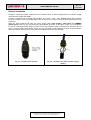
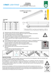
User Manual WLxx
Rev 1.0
29-09-2011
W-Light Luminaire 12/24VDC
Features
Power supply
Luminous flux reduction *
Working ambient temperature
Protection degree
Electric insulation class
Mounting
Electric cabling
Outside diameter
power supply cable
Inside section
power supply cable
Omologations
10 - 30VDC
-30%
-20°C ~ +60°C
IP 65
III (SELV)
Top-pole or bracket 60mm Diameter
Coaxial terminal 3 poles IP 68
Warranty
2 years
Ø 5 – 13,5 mm
3 x 1,5 – 4 mmq
CE Mark
* Available only through the connection with the Western Co. SPB-Lx series charge regulators.
Mechanical installation
W-Light has got an universal attack to bracket or top-pole made of hot galvanized and painted steel Ø 60
mm. To avoid light pollution this attack has an adjustable tilt system that allows, in case of bracket
installations, to correct the bracket tilt to ensure the perfectly luminaire horizontal mounting. The
correctable bracket tilt angles are fixed and they are three: 5° / 10° / 30° (see Fig. 1).
Figura 1 – available W-Light - mechanical configurations
This document is the property of WESTERN CO. S.r.l.. All rights are reserved.
Reproduction and use of information contained within this document is
forbidden without the written consent of WESTERN CO. S.r.l..
User Manual WLxx
Rev 1.0
29-09-2011
Electric installation
W-Light is a luminaire with a III (SELV) electric insulation class. It must be supplied with a constant voltage
value between 10VDC and 30VDC.
W-Light is equipped with a 500mm long H07RN-F 3x1.5 mmq. (+VDC, -VDC, DIMMER) black cable outgoing
from the luminaire internal compartment and connected to an input coaxial 3-poles IP68 terminal (see
Figure 2a).
Open this input terminal and cable the power supply cable +VDC (brown), -VDC (blue) and DIMMER
(yellow-green) (see Fig. 2b), respecting the right polarities as shown on the figure. There is not a feedback
in case of a luminaire wrong cabling; so take care of the polarities respect, otherwise the luminaire will not
work. In case of battery direct power supply, the only connection will be sufficient to power on the luminaire,
so this procedure can be used to verify the correct cabling inside the input terminal.
Fig. 2a – W-Light input terminal
Fig. 2b – W-Light colors map of power supply
cabling
This document is the property of WESTERN CO. S.r.l.. All rights are reserved.
Reproduction and use of information contained within this document is
forbidden without the written consent of WESTERN CO. S.r.l..