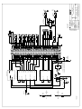
1
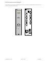
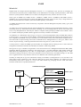
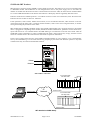
I R T Electronics Pty Ltd A.B.N. 35 000 832 575
26 Hotham Parade, ARTARMON N.S.W. 2064 AUSTRALIA
National: Phone: (02) 9439 3744
Fax: (02) 9439 7439
International:
+61 2 9439 3744
+61 2 9439 7439
Email: [email protected]
Web: www.irtelectronics.com
IRT Eurocard Type
DDA-4006
270 Mb/s ASI/SDI 8 O/P
Non-Reclocking Distribution Amplifier
Designed and manufactured in Australia
IRT can be found on the Internet at:
http://www.irtelectronics.com
4006-dda.ib.rev1.doc
Page 1 of 12
10/09/2008
DDA-4006
270 Mb/s ASI/SDI 8 O/P
Non-Reclocking Distribution Amplifier
Instruction Manual
Table of Contents
Section
Page
Operational Safety
General Description
Technical Specifications
Installation
Link Settings
Digital Video Connections
Front Panel Indicators
SMU-4000 Installation
Figure 1: SMU-4000 module
Front & rear panel connector diagrams
SNMP – What Is It?
DDA-4006 SNMP Functions
Maintenance & Storage
Warranty and Service
Equipment return
Drawing Index
2
3
4
5
5
5
5
6
6
7
8
10
11
11
11
12
This instruction manual applies to DDA-4006 later than S/N 0806101
Operational Safety:
WARNING
Operation of electronic equipment involves the use of voltages and currents that
may be dangerous to human life. Note that under certain conditions dangerous
potentials may exist in some circuits when power controls are in the OFF position.
Maintenance personnel should observe all safety regulations.
Do not make any adjustments inside equipment with power ON unless proper
precautions are observed. All internal adjustments should only be made by suitably
qualified personnel. All operational adjustments are available externally without the
need for removing covers or use of extender cards.
4006-dda.ib.rev1.doc
Page 2 of 12
10/09/2008
DDA-4006
270 Mb/s ASI/SDI 8 O/P
Non-Reclocking Distribution Amplifier
General Description
BLOCK DIAGRAM DDA-4006 SIGNAL PATH
OUTPUTS
Relay Bypass on loss of power
O/P 1
O/P 2
O/P 3
O/P 4
INPUT
EQUALISER
O/P 5
O/P 6
SIGNAL FAIL
DETECTION
O/P 7
O/P 8
SNMP
MON O/P
LINK
RL 1
RL1
ALARM O/P
Relay RL 1 = Output Alarm
The DDA-4006 270 Mb/s serial digital video distribution amplifier provides the user with a single standard module
to cover a wide range of distribution and monitoring functions for ASI or SDI signals.
Due to the fact that standard loop through techniques used in the analogue domain are unsuitable to the digital
domain most digital equipment comes with no facility to route the input signal to other locations. As a result a DA is
required at almost every point in the digital chain.
Serial digital signals also suffer severe deterioration over relatively short cable distances. The DDA-4006 provides a
means of extending the working distances that can be achieved by equalising and re-transmitting the data mid route.
The DDA-4006 may also be used to provide input equalisation for devices not having this feature, as most
unequalised inputs will only support cable lengths of less than 20 metres.
Frequent re-clocking of serial digital signals can lead to serious increases in jitter with resultant data errors. The
DDA-4006 does not include re-clocking so as to minimise these errors, leaving re-clocking to be done by the
receiving device. For applications requiring reclocking the DDA-4007 should be used.
The rear assembly now includes a bypass relay, to switch the Input (SK1) to Output 1 (SK2) in the event of a power
failure, as standard.
An optional Simple Network Management Protocol (SNMP) plug-in module is available for remote monitoring of
input status and alarm state.
The DDA-4006 is designed to fit IRT’s Standard Eurocard frame as well as IRT’s 4000 series frame for use with
IRT’s SNMP system and may be used alongside any other of IRT’s analogue or digital Eurocards.
Features:
•
•
•
•
•
•
•
For use as buffer or distribution amplifier.
8 in-phase 270 Mb/s ASI or SDI reclocked outputs.
Automatic input equalisation to 250 metres.
Automatic output muting on no input.
Relay bypass on loss of power.
Front panel indicators provide monitoring of presence of input signal at 270 Mb/s.
Optional plug-in SNMP monitoring module.
4006-dda.ib.rev1.doc
Page 3 of 12
10/09/2008
Technical Specifications
DDA-4006
Input:
Number
Impedance
Return loss
1.
75 Ohm.
>15 dB 5 MHz to 270 MHz.
Equalisation
Automatic, better than 250 metres at 270 Mb/s for Belden 8281 or
equivalent cable (reduces to approx. 200m when LK2 is closed).
Outputs:
Number
Signal level
Impedance
Return loss
DC offset
8 ASI or SDI plus one front panel monitoring output.
800 mV ± 10%.
75 Ohm.
>15 dB 5 MHz to 270 MHz.
Nil.
Performance:
Output rise time
Residual Jitter
<1 ns, (700 ps typically).
<0.1 UI (measured with up to 300m of Belden 8281 or equivalent cable).
Connectors:
BNC.
Indicators:
Power
Signal present
Power requirement:
Voltage
Consumption
LED (green) for +5 Vdc.
LED (green) when signal present.
28 Vac CT (14-0-14) or ±16 Vdc.
2.0 VA.
General:
Temperature range
Mechanical
Dimensions
Weight
Finish: Front panel
Rear assembly
Supplied accessories
Optional accessories
0 - 50° C ambient.
Suitable for mounting in IRT 19" rack chassis with input, output and power
connections on the rear panel.
6 HP x 3U Extended Eurocard (220 mm x 100 mm).
With rear assembly 340g.
Grey background, silk-screened black lettering & red IRT logo.
Detachable silk-screened PCB with direct mount connectors to Eurocard and external
signals.
Rear connector assembly with matching connector for alarm outputs.
SMU-4000 SNMP plug-in module for use with 4000 series frame fitted with SNMP
“Agent”.
Due to our policy of continuing development, these specifications are subject to change without notice.
4006-dda.ib.rev1.doc
Page 4 of 12
10/09/2008
Installation
Pre-installation:
Handling:
This equipment may contain or be connected to static sensitive devices and proper static free handling precautions
should be observed.
Where individual circuit cards are stored, they should be placed in antistatic bags. Proper antistatic procedures
should be followed when inserting or removing cards from these bags.
Power:
AC mains supply:
Ensure that operating voltage of unit and local supply voltage match and that correct rating
fuse is installed for local supply.
DC supply:
Ensure that the correct polarity is observed and that DC supply voltage is maintained within
the operating range specified.
Earthing:
The earth path is dependent on the type of frame selected. In every case particular care should be taken to ensure
that the frame is connected to earth for safety reasons. See frame manual for details.
Signal earth: For safety reasons a connection is made between signal earth and chassis earth. No attempt should be
made to break this connection.
Installation in frame or chassis:
See details in separate manual for selected frame type.
Link Settings:
LK1 is factory set for a contact make to ground on signal failure at SK10 pin 2 on the rear panel, move LK1 from
the normally closed (N/C) to the normally open (N/O) position for a break to ground on signal or power loss.
Link LK2 closed reduces the input equalisation to 200m for use in noisy environments or when a short input cable
is used.
Digital Video Connections:
Input and outputs are 75 Ω BNC type for connection with high quality 75 Ω coaxial cable. Input is self-terminating.
Front Panel Indicators:
The presence of 270 Mb/s locked signal is indicated by the ‘SIGNAL PRESENT’ front panel LED (green).
The presence of the internal +5 Vdc supply is indicated by the front panel LED (green).
4006-dda.ib.rev1.doc
Page 5 of 12
10/09/2008
SMU-4000 Installation
The SMU-4000 plug-in SNMP management controller module can only be fitted to IRT’s 4000 series modules that
are capable of being SNMP upgradeable. To determine whether a module is SNMP upgradeable, a square section
on the main PCB is silk screened and fitted with three multipin sockets – as shown below:
1J1
1J3
1J2
This is where the SMU-4000 plug-in SNMP management controller module is fitted. The three sets of multipins on
the underside of the SMU-4000 line up with the three sets of multipin sockets on the main PCB module. Align all
pins and then gently press the SMU-4000 all the way down into place.
If the SMU-4000 is not already programmed with the correct firmware to match the module that it is being plugged
into, it then needs to be programmed via the pins on the topside of the SMU-4000.
Note that installation will generally be done by IRT Electronics at the time of ordering.
Note also that an SMU-4000 will only be functionally operational when the main module that it is plugged into is
fitted into an IRT 4000 series frame fitted with a CDM-4000 SNMP agent and being interrogated by a suitable
Network Management System.
Figure 1: SMU-4000 module
4006-dda.ib.rev1.doc
Page 6 of 12
10/09/2008
Front & rear panel connector diagrams
The following front panel and rear assembly drawings are not to scale and are intended to show relative positions of
connectors, indicators and controls only.
DD A - 4 0 0 6
OUTPUTS
POWER OFF
BYPASS
SK1-SK2
SK8
SK9
PL2
SK7
SK6
SIGNAL
PRESENT
SK4
SK5
SK3
SK2
OUTPUT MON
DC
2
SK1
1
SK10
SK10 2 = Alarm
SK10 1 = Gnd
INPUT
PL 5 OUT
PL1
N140
4006-dda.ib.rev1.doc
Page 7 of 12
10/09/2008
SNMP
What Is It?
SNMP stands for Simple Network Management Protocol. It is an application layer protocol for managing IP
(Internet Protocol) based systems. SNMP enables system administrators to manage system performance, and to find
and solve system problems. SNMP runs over UDP (User Datagram Protocol), which in turn runs over IP.
Three types of SNMP exist: SNMP version 1 (SNMPv1), SNMP version 2 (SNMPv2) and SNMP version 3
(SNMPv3). It is not the intention here to discuss the differences between various versions, only to bring attention to
the fact that IRT Electronics modules, fitted with SNMP capability, use SNMPv1.
An SNMP managed network consists of three key components: Network Management Systems (NMS), agents, and
managed devices.
An NMS is the console through which the network administrator performs network management functions, such as
monitoring status (e.g. alarm states) and remote controlling, of a set of managed devices. One or more NMSs must
exist on any managed network. Generally the NMS is a computer running third party SNMP control software. There
are a number of third party SNMP software applications currently available on the market.
An NMS polls, or communicates with, an agent. An agent is a network management software module that resides in
a managed device. An agent has local knowledge of management information and translates that information into a
form compatible with SNMP. The agent, therefore, acts as an interface between the NMS and the managed devices.
The NMS sends a request message, and control commands for the managed devices, to the agent, which in turn
sends a response message, containing information about the managed devices, back to the NMS.
A managed device contains an SNMP agent and resides on a managed network. Managed devices collect and store
management information and make this information available to NMSs using SNMP.
Managed device agent variables are organised in a tree structure known as a Management Information Base (MIB).
Within the MIB are parameters pertaining to the managed device. An Object Identifier (OID) number within the
MIB defines the managed device type. This is a unique number specific to the model of managed device. Other
information relating to the device is also stored, information such as alarm states, controllable settings, etc. The MIB
tree is organised in such a way that there will be no two MIB files with conflicting placements.
Normally an NMS polls an agent for information relating to the MIB in a managed device to be sent back to the
NMS. When certain conditions are met within the MIB, such as major alarm conditions, for example, the agent
automatically sends what is known as a trap to the NMS without any prompting from the NMS. This allows
automatic notification of a predetermined event.
SNMP Block Diagram
NMS
IP
Network
NMS
4006-dda.ib.rev1.doc
Page 8 of 12
SNMP Agent
Protocol Engine
MIB
SNMP Agent
SNMP Agent
Protocol Engine
MIB
SNMP Agent
SNMP Agent
Protocol Engine
MIB
SNMP Agent
10/09/2008
SNMP with IRT Products
IRT Electronics currently employs SNMPv1 with its 4000 series frame. The frame acts as an agent when fitted with
a CDM-4000 module. This module has its own designated slot next to the power supply so as to not affect the
number of modules that the frame will take. Communication between the NMS, the frame and its loaded modules
are via this CDM-4000 module. Note that the NMS software is third party and not supplied by IRT Electronics.
Ethernet connection for SNMP operation is via an RJ45 connector on the rear of the frame, below the mains inlet.
Ethernet rate runs at either 10 baseT or 100 baseT.
Frame parameters, such as Name, Address and Location, are set via an RS232 interface, a D9 connector on the rear
of the frame below the mains inlet. A software terminal emulator, such as Tera Term or HyperTerminal, is used for
setting and reading the parameters of the frame.
IRT modules that are SNMP compatible need a plug-in SMU-4000 module with a program relevant to the module
that it is plugged into. Depending on the module, besides the module identification, parameters such as alarm states,
inputs and controls etc. are communicated to the CDM-4000 agent via a data bus on the rear of the frame. Thus the
CDM-4000 collects information on what is loaded within the frame, what positions they occupy, and their current
status for communication to the NMS when the NMS sends a request for information.
In the event of a major alarm from any of the SNMP compatible modules, or power supplies, a trap is automatically
sent by the CDM-4000 agent to the NMS without any prompting by the NMS. This alerts the operator to any fault
conditions that may exist that need immediate attention.
110/240 V 50/60 Hz
0.7 A (max.)
FRU-4000
FRAME
FUSES
220/240 Vac
500 mA S.B.
110/120 Vac
1A S.B.
RS232
Alarm
Ethernet
+
48Vdc
AS3260 approval no.: CS6346N
Ass. no.: 804692
IRT SNMP Connections
IRT modules fitted
with SMU-4000
NMS
Ethernet Cable
IP
Network
CDM-4000
PSU’s
IRT 4000 Series Frame
Ethernet Cable
IRT modules fitted
with SMU-4000
CDM-4000
PSU’s
IRT 4000 Series Frame
Ethernet Cable
IRT 4000 Series SNMP Setup
4006-dda.ib.rev1.doc
Page 9 of 12
10/09/2008
DDA-4006 SNMP Functions:
With the DDA-4006 fitted with the optional plug-in SMU-4000 SNMP module, programmed with firmware to suit,
and installed in an IRT 4000 series frame with SNMP capability, it is possible to remotely monitor the presence of
an input and the state of the urgent alarm using an NMS. Traps can also be set for whenever an urgent alarm occurs
or clears.
4006-dda.ib.rev1.doc
Page 10 of 12
10/09/2008
Maintenance & Storage
Maintenance:
No regular maintenance is required.
Care however should be taken to ensure that all connectors are kept clean and free from contamination of any kind.
This is especially important in fibre optic equipment where cleanliness of optical connections is critical to
performance.
Storage:
If the equipment is not to be used for an extended period, it is recommended the whole unit be placed in a sealed
plastic bag to prevent dust contamination. In areas of high humidity a suitably sized bag of silica gel should be
included to deter corrosion.
Where individual circuit cards are stored, they should be placed in antistatic bags. Proper antistatic procedures
should be followed when inserting or removing cards from these bags.
Warranty & Service
Equipment is covered by a limited warranty period of three years from date of first delivery unless contrary
conditions apply under a particular contract of supply. For situations when “No Fault Found” for repairs, a
minimum charge of 1 hour’s labour, at IRT’s current labour charge rate, will apply, whether the equipment is within
the warranty period or not.
Equipment warranty is limited to faults attributable to defects in original design or manufacture. Warranty on
components shall be extended by IRT only to the extent obtainable from the component supplier.
Equipment return:
Before arranging service, ensure that the fault is in the unit to be serviced and not in associated equipment. If
possible, confirm this by substitution.
Before returning equipment contact should be made with IRT or your local agent to determine whether the
equipment can be serviced in the field or should be returned for repair.
The equipment should be properly packed for return observing antistatic procedures.
The following information should accompany the unit to be returned:
1.
2.
3.
4.
5.
6.
7.
A fault report should be included indicating the nature of the fault
The operating conditions under which the fault initially occurred.
Any additional information, which may be of assistance in fault location and remedy.
A contact name and telephone and fax numbers.
Details of payment method for items not covered by warranty.
Full return address.
For situations when “No Fault Found” for repairs, a minimum charge of 1 hour’s labour will apply,
whether the equipment is within the warranty period or not. Contact IRT for current hourly rate.
Please note that all freight charges are the responsibility of the customer.
The equipment should be returned to the agent who originally supplied the equipment or, where this is not
possible, to IRT direct as follows.
Equipment Service
IRT Electronics Pty Ltd
26 Hotham Parade
ARTARMON
N.S.W.
2064
AUSTRALIA
Phone:
Email:
4006-dda.ib.rev1.doc
61 2 9439 3744
[email protected]
Page 11 of 12
Fax:
61 2 9439 7439
10/09/2008
Drawing Index
Note: Components marked n/c on the diagrams are optional and are not included on standard production units. They
are shown to assist with interpretation of additional or optional functions, which may be included or are necessary
for factory set-up procedures.
Drawing #
Sheet #
Description
804936
1
DDA-4006 Circuit Schematic
4006-dda.ib.rev1.doc
Page 12 of 12
10/09/2008
PCB 804937
'SIGNAL'
'DC'
LD2
HLMP-1503
'grn'
R35
680R
+5V
2
LD1
HLMP-1503
'grn'
R36
680R
+5V
SK101
2
1
22R
R41
1
1
R6
10K
2
2
BAS16
D2
+5V
+5V
C11
100nF
Input
Carrier Detect
+5V
1
2
4u7
RL1A
V23026
C33
5
2
n.o.
ALARM CIRCUIT
10
1
n.c.
LK1
C41
GNDA
C40
10nF
10nF
TO GROUND ON ALARM, AS SET BY LK1
CONTACT CLOSURE (OR BREAK)
RL1B
AC 4
AC 3
GND
804936i3s3.sch
AC 2
+5V
AC 1
Power Supply Circuit
Output 1
Output 2
Output 3
Output 4
Output 5
Output 6
Output 7
GND
Monitor O/P
Output 8
+5V
Input Equaliser and Output Drivers
804936i3s2.sch
Q1
BSS123
1
TX
CD
804936i3s4.sch
RX
RELAY RA
+5V
1
F5
RXE020
POLYFUSE
10nF
2
C39
1A
1B
2A
2B
3A
3B
4A
4B
5A
5B
6A
6B
7A
7B
8A
8B
9A
9B
10A
10B
11A
11B
12A
12B
13A
13B
14A
14B
15A
15B
16A
16B
17A
17B
18A
18B
19A
19B
20A
20B
21A
21B
22A
22B
23A
23B
24A
24B
25A
25B
26A
26B
27A
27B
28A
28B
29A
29B
30A
30B
31A
31B
32A
32B
DIN64RA
P1
DIN64
J1
1A
1B
2A
2B
3A
3B
4A
4B
5A
5B
6A
6B
7A
7B
8A
8B
9A
9B
10A
10B
11A
11B
12A
12B
13A
13B
14A
14B
15A
15B
16A
16B
17A
17B
18A
18B
19A
19B
20A
20B
21A
21B
22A
22B
23A
23B
24A
24B
25A
25B
26A
26B
27A
27B
28A
28B
29A
29B
30A
30B
31A
31B
32A
32B
J1/32A
R3R
L3R
R4R
L4R
R5R
L5R
R6R
L6R
R7R
L7R
R8R
L8R
R9R
L9R
2
2
2
2
2
2
2
2
2
2
2
2
2
2
1
1
68R
R1R
2
2
L1R 15nH
1
1
1
1
1
1
1
1
1
1
1
1
1
1
P3
6
4
2
1
SK10
SK3
SK4
SK5
SK6
SK7
SK8
1
2
3
1
3
5
7
9
2 RX
OUTPUTS
SK9
5
3
TX 1
P2
J2
2 03-04-2008 ECR1853
3 26-06-2008 ECR1863
K.N.
Date: 10-Sep-2008
Revision: 3
ENG. APP.
CHECKED
DRAWN
DO NOT COPY NOR
DISCLOSE TO ANY
THIRD PARTY
WITHOUT WRITTEN
CONSENT
COPYRIGHT
R1-R9 = 68R
L1-L11 = 15nH
2
1
Sheet
1 of 4
DDA-4006
SDI/ASI Distribution Amplifier
SK1
INPUT
SK2
Drawing No. 804936
Title
R10R 39R
2
1
L10R 15nH
R11R 68R
2
2
1
L11R 15nH
1
IRT Electronics Pty. Ltd.
ARTARMON NSW AUSTRALIA 2064
SCALE
N.T.S.
A3
SIZE
J1/32A
RL1R
RELAY G6K-2F-RF
4
5
ALARM
3
6
2
1
2
1
2
1
3
1
2
7
MON. O/P
2
1
3
8
3
2
1
3
2
1
2
1
2
1
1
8
Control Interface
1 15-04-2004