1
*1t
PATENT WO99/40361
6TFSTBOEPQFSBUPSTNBOVBMGPSBSUt
.BOVBMFEVTPFEFMMPQFSBUPSFQFSBSUt
ENGLISH INDEX
Safety informations ........................................................................................................................... page 2
Technical features .............................................................................................................................. page 3
Before using....................................................................................................................................... page 4
Lamp installation, replacement and setting .................................................................................... page 5
Installation of the dust proof filters .................................................................................................. page 6
Control panel and configuration ...................................................................................................... page 7
Programming functions .................................................................................................................... page 8
Use of the CityColor in DMX 512 ..................................................................................................... page 9
DMX signal connection ..................................................................................................................... page 10
DMX line and termination ................................................................................................................ page 11
Automode functioning ...................................................................................................................... page 12
Troubleshooting ............................................................................................................................... page 13
System board connection ................................................................................................................ page 15
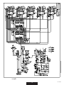
Electric diagrams
.......................................................................................................................... page 17
Components and parts...................................................................................................................... page 22
Technical drawings ............................................................................................................................ page 23
Appendix A (DMX values)................................................................................................................. page 26
*1t
Appendix B (games) .......................................................................................................................... page 27
PATENT WO99/40361
!
WARNING
SAFETY INFORMATION
READ ALL CAUTIONS AND WARNINGS PRIOR TO OPERATE THIS EQUIPMENT.
INSTRUCTION TO PREVENT INJURY OR DAMAGE DUE TO ELECTRIC SHOCK, FIRE, MECHANICAL HAZARDS,
UV RADIATION HAZARDS AND DANGEROUS MATTERS.
t1305&$5*0/"("*/45%"/(&3064."55&34
At the end of its working life, the product must not be disposed of as urbamn waste. It must be taken to a special local
authority differentiate waste collection centre or to a dealer providing this service. The wrong disposal must be cause of
environment and people damages in the presence of possible dangerous matters. There are provided for sanctions to a
VOBVUIPSJ[FEEJTQPTBMPGUIFTFQSPEVDUT
t1305&$5*0/"("*/54'*3&
1)This equipment is designed for use with the following lamps only:
1IJMJQT.)/4"8F 1IJMJQT.4"%&8
DO NOT USE ANY OTHER TYPE OF LAMP!
2) Maintain minimum distance of 0.5 meter from walls or any other type flammable surfaces.
2m
3) Maintain minimum distance of 2.0 meter to lighted objects .
3FQMBDFGVTFTPOMZXJUIUIFTQFDJmFEUZQFBOESBUJOH
5) Do not install the spot close to heat sources. Do not lay the connection cable on the spot when it is warm.
t1305&$5*0/"("*/45&-&$53*$4)0$,
1) This equipment must be earthed.
2) Class I equipment. The power supply cord includes a protective earthing conductor as part of the cord.
3) Disconnect power before installing the lamp or servicing (service personnel).
t1305&$5*0/"("*/45.&$)"/*$"-)";"3%4
1) Use secondary safety chain when fixing this equipment.
)PUMBNQFYQMPTJPOIB[BSE%POPUPQFOUIFFRVJQNFOUGPSTFDPOETBGUFSTXJUDIJOHPGG
3) Equipment surface may reach temperature up to 100°C. Allow about five minutes before handling.
3FQMBDFUIFMBNQJGJUJTEBNBHFEPSUIFSNBMMZEFGPSNFE
t1305&$5*0/"("*/45673"%*"5*0/)";"3%4
1) Do not start on this equipment without lamp enclosure or if the protection screens, or ultraviolets screens are damaged.
2) The protection screens, the lenses, or the ultraviolet filters must be replaced if they are visibly damaged and their effectiveness
has been reduced, for example, by cracks or deep scratches. Part 140/a, code SDO52000015
3) Do not look directly at the lamp while lamp is on.
F
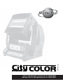
INTRODUCTION
Thank you for using our flood projector CityColor.
The CityColor projects, thanks to an extremely efficient optic system (patent n. WO99/40361), a powerful light beam which can create
numberless color shades. Its performances, in terms of luminousity and lighted surfaces, can reach incredible levels.
The CityColor IP54 comes in the following versions:
t"SU$*5:$0-03*18
t"SU $*5:$0-03*18)JHI1PXFS
The CityColor can work in automatic mode or in synchro mode, otherwise may be controlled by 8 bit DMX controllers
The input protocol is the DMX 512. To drive the CityColor we suggest to use either our controller DMX Control Spot, the
Control Show 512 the Easy Control or the Fancy.
To make the most of its possibilites and for a correct functioning of this unit in the years to come, we suggest you to read carefully
this manual before connecting or putting the spot into use. By doing so you will gain experience with its commands and connections
and you will be easily able to use it.
!
WARNING
Check that the spot has not been damaged during transport. If it has been damaged or it does not work, address
the seller. Whether the spot has been shipped to you directly, please contact the shipping company.
Only the consignee (person or company) can claim for these damages.
rel. 7-0308
2
YOUR REFERENCE
Always remember to give the serial number and to specify the model any time you address the seller for information or assistance.
BASIC KIT
The basic kit of the CityColor flood projector consist of:
t1SPKFDUPS
t6TFSTNBOVBM
t1PXFSDPOOFDUPS
t4UVEJP%VFXBSSBOUZ
Available on request:
tBSUBCBSOEPPSUPEFmOFJMMVNJOBUFETVSGBDF
tBSUBBOUJHMBSF
tBSUB9-3QJONBMF*1DPOOFDUPST
tBSUC9-3QJOGFNBMF*1DPOOFDUPST
t-BNQ
TECHNICAL FEATURES
tLAMPS
.)/4"81)*-*14 BSU
Color temperature: 5.600°K
Lamp life: 2.500 hours
Luminous flux 180.000 lm
.4"%&81)*-*14 BSU
Color temperature 6.000°K
Lamp life 2.000 hours
Luminous flux 260.000 lm
t015*$$0-034:45&.
'VMM$:.DPMPSNJYJOH VOMJNJUFEWBSJFUZPGDPMPVSTBOETIBEFT)JHISFTPMVUJPOTUFQQFSNPUPST
Shutter + dimmer. The color changer can be drived with 4 different speeds or in real time.
tBEAM ANGLE: (50% intensity) 50°x52°
t$0/530-*/165
SUBOEBSEJOUFSGBDF34PQUPDPVQMFUJOQVU
Protocol: USITT DMX 512
t4&561"/%$0/'*(63"5*0/
On the control panel with menu and buttons
tAUTOMODE
Stand-alone control: auto mode function master/slave (synchro mode) with 27 programs
t*13"5&*1
t108&34611-:: (art. 0002) magnetic ballast
3BUFEWPMUBHF7~)[
0OSFRVFTU7~)[7~)[7~)[7~)[
3BUFEDVSSFOU"!7~
3BUFEQPXFS8
t108&34611-:: (art. 0003) magnetic ballast
3BUFEWPMUBHF7~)[
0OSFRVFTU7~)[7~)[7~)[7~)[
3BUFEDVSSFOU"!7~
3BUFEQPXFS8
t108&3'"$503$033&$503 built-in cos Ø 0.9
t%.9$)"//&-4
ch1 = motors speed
ch2 = cyan
ch3 = yellow
ch4 = magenta
ch5 = dimmer
ch6 = basic colors + rainbow
ch7 = remote reset/lamp off
tDIMENSIONS (wxdxh)
mm 780x560x740
t8&*()5
art. 0002: 56 kgs. net
art. 0003: 69 kgs. net
3
rel. 7-0308
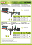
CIRCUIT BREAKER
."*/470-5"(&
In
Id
7
32A
0,03A
Studio Due
*/165$0//&$503
'038
CITYCOLOR art. 0002
Keep at least a distance of 0,5 mts between the apparatus and
inflammable surface nearby.
Disconnect the unit from power before servicing.
230Vac; 15A - 50Hz
SN
QC
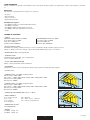
1*/$0//&$503'03108&3*/165
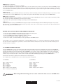
CONDUCTOR SIZES (length < 20mt.)
."*/470-5"(&
$30444&-&$5*0/"-"3&"4
7
3X1,5 mm2 (minimum)
/ /&653"- -*7&
(306/%
IP 67
pict.1
IP 67
*/165$0//&$503
'038)*()108&3
BEFORE USING
!
WARNING
The equipment must be earthed.
IP 54 rate: the equipment must be installed on the horizontal plane.
3FBEBMMDBVUJPOTBOEXBSOJOHTUPQBHFQSJPSUPJOTUBMMUIJTFRVJQNFOU1BSUJDVMBSMZ SFBEUIFGPMMPX
%JTDPOOFDUQPXFSCFGPSFMBNQTSFQMBDFNFOUPSTFSWJDJOH TFSWJDFQFSTPOOFM
2) Do not open the lamp cover for 300 seconds after switching off
3) Wear gloves and goggles to re-lamping or to work inside the unit (service personnel)
Before connecting the equipment to the power system: make sure that the mains voltage and frequency correspond to rated
values.
t5IF$JUZ$PMPSDBOCFFRVJQQFEGPSBNBJOTWPMUBHF7~)[
POSFRVFTU7~)[7~)[7~)[7~)[
'PSBQPXFSTVQQMZPG7~7~ it is necessary to use one auto transformer with the following features:
t0VUQVUWPMUBHF7~
t0VUQVUDVSSFOU"!7~ (for art. 0002)
t0VUQVUDVSSFOU"!7~ (for art. 0003)
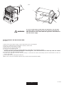
The power supply cords construction is shown in pict.1. For connection to the mains supply proceed as pict.1.
5IFFRVJQNFOUNVTUCFDPOOFDUFEUPCSBODIDJSDVJUIBWJOHBDJSDVJUCSFBDLFS*O"t*E" 7~) (art. 0002) or
*O"t*E" 7~) (art.0003)
a) Do not install the spot close to the heat sources. Observe minimum distance between the spots of 1.5 meters. Do not lay the
connection cable on the spot when it is warm.
b) This unit must be positioned as to allow its ventilation. Be careful not to acclude the in-out ventilating grilles.
c) The unit must be positioned at least 50cm. from walls or other flammable surfaces.
d) Observe minimum distance to lighted objects of 5 meters.
External surface temperature Ta 35°C:
t"GUFSNJOVUFTXPSL5D×$
t0ODFUIFUIFSNJDCBMBODFIBTCFFOPCUBJOFE5D×$
4) The protection screens, the lenses, or the ultraviolet filters must be replaced if they are visibly damaged and their effectiveness
has been reduced, for example, by cracks or deep scratches.
5) The lamp must be replaced if it has been damaged or thermally deformed.
6) Clean regularly the in-out ventilating grilles.
7) Do not handle the spot by taking it by the head, but always by using the special handles.
rel. 7-0308
4
G
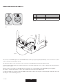
pict.2
E
A
C
C
!
WARNING
D
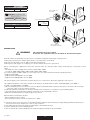
In case of replacement of the lamp or maintenance, do not open
the fixture unless 5 minutes have passed from the switching off.
This operation has to be done when the apparatus is disconnected
from the mains supply
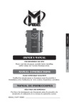
INSTALLATION OF THE DISCHARGE LAMP
(see pic.2)
3)
5)
6)
%JTDPOOFDUQPXFSCFGPSFMBNQTSFQMBDFNFOU8FBSHMPWFTBOEHPHHMFT
3FNPWFDPNQMFUFMZUIFQPNNFMT " POUIFCBTFPGUIFIFBE
Open the base of the lamp room (G)
3FNPWFUIFUXPMBUFSBMSFnFDUPST $
Lift up the two lampholder (D)
Install the new lamp. Taking care that protuberance of the bulb is set towards the reflector
Do not touch the quarz bulb with fingers. If this happenes, clean the bulb before use with dry cloth and alcohol.
7) Put down the two upper lampholders (D)
8) Connect the cables (E) to the two ends of the lamp or connect the two cables of the lamp to the two red insulators on the rear
panel of the head.
9) Put in again the two lateral plane reflectors.
10) Close the rear panel and install again the two pommels (A) and hold them tightly.
5
rel. 7-0308
IP RATE
The declared IP rate of the CityColor comes supported at these conditions:
tUIFJOTUBMMBUJPOPGUIFmYUVSFPOBXJEFBOETUBCMFTVSGBDF
tUIFBJSDPPMJOHJOQVUBOEPVUQVUBSFMPDBUFEPOUIFCBTFPGUIFTJEFTIFMM it is not possible to install the fixture outdoor with the ballast upwards
tZPVNVTUVTFUIFmMUFSTVQQMJFEXJUIUIFCBTJDLJUGPSUIF*13"5&
!
WARNING
The CityColor has a IP rate 44 without filters installed and an IP RATE 54 with filters installed.
You must use the filters in critical working conditions and, normally, when the fixture works outdoor.
You must remove the filters when the ambient temperature is over 35°C.
You must regularly clean the filters to allow the correct cooling of the fixture.
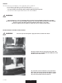
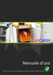
INSTALLATION OF THE DUST PROOF FILTERS
!
WARNING
You must operate with power supply disconnected from the fixture
You must remove the two side protective shells. The
two filters must be assembled on the bulkheads at the
bottom of the side brackets.
pict.3
Pay attention to the installation: dust proof filters
must stick correctly to prevent the entrance of the
dust. You must control that the two filters completely cover the overall of the air entrance.
rel. 7-0308
6
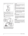
pict.4
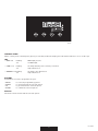
CONTROL PANEL
On the control panel of the CityColor (pict.4) you can find, besides the display, the leds and the buttons to use to set the spot.
LED
ti%.9wMFE
tw-".1wMFE
nBTIJOH
off:
%.9JOQVUQSFTFOU
no DMX input
nBTIJOH
off:
UIFMBNQTXJUDIJOHPGGJTSFNPUFMZDPOUSPMMFE
lamp switched on
tw%*..&3wMFE nBTIJOH
off:
UIFMBNQJTEJNNFSFE
lamp switched on
BUTTONS
Four buttons are used to programme the spot:
t.&/6
tDOWN
tUP
t&/5&3
UPTFMFDUUIFQSPHSBNNJOHPQUJPOT
to go backward in the selected options
to go forward in the selected options
to confirm the selected options
DISPLAY
Shows the various menus and the selected options.
7
rel. 7-0308
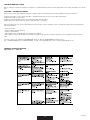
SUMMARY OF THE PROGRAMMING FUNCTIONS OF THE CITYCOLOR
Addr
nChn
teSt
Mode
LHrS
FLIP
FHrS
rSEt
"CPVUUXFOUZTFDPOETBGUFSUIFTXJUDIJOHPO UIFOVNCFSPGUIFTPGUXBSFWFSTJPOXJMMCFTIPXOPOUIFEJTQMBZJOi9@wGPSNBU
Afterwards the first of the eight available menus will appear:
Addr
Mode
LHrS
FHrS
nChn
teSt
FLIP
rSEt
to assign the DMX-512 address
DMX512 mode, master with pre-set selection, slave
lamp working hours
fixture total working hours
channels number
auto-test
display inversion
reset of the spot
To select any of the given options, press the MENU button up to when the required one is shown.
Addr (Address)
5PWJTVBMJTFUIF%.9BEESFTTQSFTT&/5&3
5PNPEJGZUIFBEESFTTQSFTT%PXOBOE6QCVUUPOTBOE PODFUIFSFRVJSFEBEESFTTIBTCFFOTFMFDUFE QSFTTBOELFFQ&/5&3QSFTTFE
up to when the display stops flashing (it flashes to indicate that the selected option is different from the pre-set one). To go back to
the options without making any change, press the MENU button.
Mode (Mode)
5PWJTVBMJTFUIJTNPEFQSFTT&/5&3
6TF%PXOBOE6QCVUUPOTUPDIBOHFUIFNPEFBOE PODFUIFSFRVJSFEPOFIBTCFFOTFMFDUFE QSFTTBOELFFQ&/5&3QSFTTFEVQ
to when the display stops flashing (it flashes to indicate that the selected option is different from the pre-set one). The available
PQUJPOTBSFOP OPSNBM GPSUIFGVODUJPOJOHJO%.9SFDFQUJPO1Sy1S QSFTFUy GPSUIFNBTUFSGVODUJPOJOHXJUIUIFSFspective game, SL (slave) for the functioning as slave. To go back to the options without any change, press the MENU button.
LHrS -BNQ)PVST
5PWJTVBMJTFUIFOVNCFSPGXPSLJOHIPVSTPGMBNQQSFTT&/5&3
The maximum countable number of hours is 3000. Exceeding this number, the display will show gr3t (greater than 3 thousands).
5PSFTFUUIFDPVOUFSQSFTTTJNVMUBOFPVTMZCVUUPOT%PXOBOE61UIFEJTQMBZXJMMTIPX$--) DMFBSMBNQIPVST 5PHPCBDLUPUIF
options without making any change, press the MENU button.
FHrS (Fixture hours)
5PWJTVBMJTFUIFOVNCFSPGXPSLJOHIPVSTPGmYUVSFQSFTT&/5&3
The maximum countable number of hours is 3000. Exceeding this number, the display will show gr3t (greater than 3 thousands). To
reset the counter press simultaneously buttons Down and UP. A control of the memory will be run and all the default settings will be
stored: the display will then show Init. If the memory is damaged, the display will show the message FAIL. To go back to the options
without making any change, press the MENU button.
rel. 7-0308
8
nChn (Number of Channel)
5PWJTVBMJTFUIFOVNCFSPGDIBOOFMQSFTT&/5&3
6TF%PXOBOE6QCVUUPOTUPDIBOHFUIFDIBOOFMBOE PODFUIFSFRVJSFEPOFIBTCFFOTFMFDUFE QSFTTBOELFFQ&/5&3QSFTTFE
up to when the display stops flashing (it flashes to indicate that the selected option is different from the pre-set one). It is possible
to set 6 channels or 7 channels ( remote reset and remote lamp switch off ). To go back to the options without making any change,
press the MENU button.
teSt (Autotest)
5PJOTFSUUIFBVUPUFTUQSFTT&/5&3BOELFFQJUQSFTTFEVQUPXIFOUIFEJTQMBZTIPXTUIFnBTIJOHNFTTBHFUPO UFTUPO 5PUBLF
off the auto-test press the MENU button. To go back to the options without making any change, press the MENU button.
FLIP (Display overturning)
5IFEJTQMBZWJTVBMJTBUJPODBOCFTUBOEBSEPSPWFSUVSOFECZQSFTTJOHUIF&/5&3CVUUPOUIFUXPNPEFTXJMMCFBMUFSOBUJWFMZWJTJCMF
The selected one will be immediately stored in the spot setting.
To go back to the options without making any change, press the MENU button.
rSEt 3FTFU
5PSVOUIFDPNQMFUFSFTFUQSFTT&/5&3BOELFFQJUQSFTTFEVQUPXIFOUIFEJTQMBZTIPXTUIFnBTIJOHNFTTBHFSPO SFTFUPO Once the reset procedure has been completed the spot will go back to the normal setting. To go back to the options without making any change, press the MENU button.
DRIVING THE CITYCOLOR WITH A DMX REMOTE CONTROLLER
t4FMFDUUIFSFRVFTUFE%.9TUBSUJOHBEESFTTCZPQFSBUJOHPOUIFAddr option
t4FMFDUUIFSFRVFTUFEOVNCFSPGDIBOOFMXJUI/$IOPQUJPO
t$POOFDUUIF%.9TJHOBMCFUXFFOUIFmYUVSFBOEUIFDPOUSPMMFS
t$IFDLUIBUUIF%.9MFEJTnBTJOH %.9TJHOBMQSFTFOU
t*GUIFSFJTOPTJHOBM ZPVNVTUNBOVBMMZSFTFUCZPQFSBUJOHPOUIF3&4&5 option
It is possible to choose a standard configuration occupying 6 DMX channels, or a enanched configurationoccupying 7 channels.
Use the enanched configuration if you want to activate channel 7 which enables the reset of the motors and the switching off of
the lamp from the controller.
6/7 CHANNELS MODE SELECTION
1SFTTUIF.&/6CVUUPOPOUIFDPOUSPMQBOFMVQUPXIFOUIFPQUJPOO$IOJTTIPXOPOUIFEJTQMBZ TFMFDUJUCZQSFTTJOH&/5&3
and the set indication will appear (6 or 7 channels). If you want to activate channel 7 you must set 6 channels on the display. Pass
through the numbers by pressing the buttons UP and DOWN: once you have set the required number, store it by pressing the
&/5&3CVUUPOBOELFFQJUQSFTTFEVQUPXIFOUIFEJTQMBZTUPQTnBTIJOH UIFnBTIJOHTIPXTUIBUUIFTFMFDUFEPQUJPOJTEJGGFSFOU
from the one previously stored). To exit from the selected option without making any change press the MENU button.
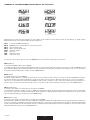
)FSFCFMPXJTTIPXOUIFDPNQMFUFMJTUPGUIFGVODUJPOTPGUIF$JUZ$PMPS
5IFDPNQMFUFMJTUPGUIF%.9WBMVFTDBOCFGPVOEJOBQQFOEJYi"w QBHF
$)"//&-4
$)
$)
$)
$)
$)
$)
$)
!
.PUPSTQFFE
$ZBO :FMMPX .BHFOUB
%JNNFS
#BTJDDPMPST SBJOCPX
3FNPUFSFTFU-BNQPGG
WARNING
$)"//&-4
$)
$)
$)
$)
$)
$)
.PUPSTQFFE
$ZBO
:FMMPX
.BHFOUB
%JNNFS
#BTJDDPMPST SBJOCPX
When using CYM color mixing, the basic colors channel # 6 must be set at: 00=DMX value
9
rel. 7-0308
CONNECTION THE DATA LINK (DMX 512)
PIN
WIRE
SIGNAL
1
4)*&-%
(306/%3&563/07
2
*//&3$0/%6$503
%"5"$0.1-&.&/5 */7&35&%
3
*//&3$0/%6$503
%"5"536&
/0/*/7&35&%
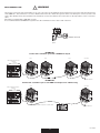
pict.5a
pict.5
fig.5c
fig.5b
5IFDPOOFDUJPOPGUIF%.9TJHOBMUPUIF$*5:$0-03NVTUCFNBEFCZVTJOHUIFTJHOBMJOQVU9-3QJODPOOFDUPSTXIJDIBSFMPDBUFE
on the control panel of the fixture. (pict.5)
The pin nomenclature of the connectors for the connection to the DMX signal is listed in the table. (pict.5a)
In order to avoid any problem in the signal transmission, it is warmly suggested to use a cable for high speed data transmission
(sect. > 2x0.25 + gnd).
If the lines have a total length over 150-200 mts it is suggested to use a signal amplifier (art. 3004 - DMX repeter amplifier).
The usage of a normal microphonic or audio cable is suggested only for lines max 100 mts long.
To ensure the IP54 rate you must connect the DMX cable inside the base. Use the given cables fixing (pict. 5b) and connect by
following the cables numbering (pict. 5c).
rel. 7-0308
10
!
DMX TERMINAL LINE
WARNING
The wrong connection of the terminal line or its non-connection are probably the most frequent reasons for the defective functioning
PGUIF%.9MJOF5IFUFSNJOBUPSJTBSFTJTUPSmUUFECFUXFFOUIFUXPiEBUBwMJOFT QJOTBOEPGBO9-3QJODPOOFDUPS BUUIFFOE
of the cable furthest from the transmitter. The terminator resistor should have the same value as the impedance of the connection
cable.
We supply a terminal with a 100 Ohm resistor.
It is recommanded that all DMX 512 systems have the termination resistor at the and of the line.
5&3.*/"-3&4*4503
pict.6
EXAMPLE 1
Connection controller-spot with 1 DMX 512 output
SPOT
SPOT
SPOT
LAST SPOT
%.9$0/530--&303-*()5
CONSOLE
5&3.*/"-3&4*4503
EXAMPLE 2
Connection controller-spot to one DMX 512 output over 150mts long
SPOT
LAST SPOT
%.9$0/530--&303-*()5
CONSOLE
LINE > 150mts (with microphonic or audio cable)
5&3.*/"-3&4*4503
4*(/"-".1-*'*&3
11
rel. 7-0308
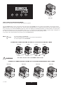
."45&3
pict.7
USE OF THE CITYCOLOR IN AUTO-MODE
"TIPSUMJTUPGUIFHBNFTDBOCFGPVOEJOBQQFOEJYi#w QBHF
Press the MENU button on the control panel up to when the option MODE (pict. 7) is shown on the display, select it by pressing
&/5&3BOEUIFTFUJOEJDBUJPOXJMMBQQFBS OP4- 6TF%PXOBOE6QCVUUPOTUPDIBOHFUIFNPEFBOE PODFUIFSFRVJSFEPOFIBT
CFFOTFMFDUFE QSFTTBOELFFQ&/5&3QSFTTFEVQUPXIFOUIFEJTQMBZTUPQTnBTIJOH JUnBTIFTUPJOEJDBUFUIBUUIFTFMFDUFEPQUJPO
JTEJGGFSFOUGSPNUIFQSFTFUPOF 5IFBWBJMBCMFPQUJPOTBSFOP OPSNBM GPSUIFGVODUJPOJOHJO%.9SFDFQUJPO1Sy1S QSFTFU
y GPSUIFNBTUFSGVODUJPOJOHXJUIUIFSFTQFDUJWFHBNF 4- TMBWF GPSUIFGVODUJPOJOHBTTMBWF
To go back to the options without any change, press the MENU button.
Mode
no
Pr1..Pr27
SL
use of the CityColor in DMX-512
master functioning with execution of the 27 stored programme
VTFPGUIF$JUZ$PMPSJO4-"7&.0%&
EXAMPLE OF CONNECTION AND SETTING OF 4 CITYCOLOR IN SYNCHRO - MODE
."45&3
!
WARNING
4-"7&
4-"7&
4-"7&
The cables are the same as the DMX standard cable
EXAMPLE OF CONNECTION AND SETTING OF 4 CITYCOLOR IN INDIPENDENT AUTO - MODE
."45&3
rel. 7-0308
."45&3
."45&3
12
."45&3
TROUBLESHOOTING GUIDE
Before calling for technical assistance, follow the recommended procedures in this appendix to solve many problems on your fixture.
$"65*0/t#&'03&:06#&(*/
Before you perform any troubleshooting procedures read the following personnel and equipment safety precautions:
3FGFSTFSWJDJOHUPTFSWJDFQFSTPOOFM 25RVBMJmFEUFDIOJDJBO OPVTFSTFSWJDFBCMFQBSUTJOTJEF
2) Wear hand and eye protection
3) Wait at least five minutes before accessing the lamp after operation
%JTDPOOFDUUIFVOJUGSPNQPXFSCFGPSFSFNPWJOHBOZDPWFS 25
If the procedures do not solve your problem and you need to call for assistance, please provide the support technician with the
follow information:
t$VTUPNFSOBNF
t1IPOFOVNCFSBOEGBYOVNCFS
t'JYUVSFTFSJBMOVNCFS
t.FTTBHFUIBUBSFZPVEJTQMBZFEPOZPVS$JUZDPMPSEJTQMBZ
t%FTDSJQUJPOPGUIFQSPCMFNBOEUIFUSPVCMFTIPPUJOHQSPDFEVSFTUIBUZPVIBWFQFSGPSNFETPGBSUPEJBHOPTFBOESFTPMWFUIF
fault.
:PVDBODPOUBDUZPVSBVUIPSJ[FE456%*0%6&EFBMFSPSEJSFDUMZ456%*0%6&5FDIOJDBM4FSWJDF
UFM PSGBY FNBJMTFSWJDF!TUVEJPEVFDPNPSDVTUPNFS!TUVEJPEVFDPN
GENERAL TROUBLESHOOTING
"QQFOEJYi$wt5BCMF"
14
13
rel. 7-0308
14
DATA LINK (512 DMX) TROUBLESHOOTING
"QQFOEJYi$wt5BCMF"
rel. 7-0308
14
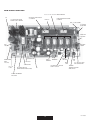
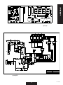
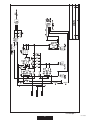
MAIN BOARD CONNECTION
66666-.0503%3*7&3
C65
67*1&348*5$)*/(
108&34611-:%3*7&3
6.*$304-"7&.0503
$$4-"7&99
6.*$30."45&3.0503
$$%3799
-&% 7
-&% 70150%.9
U13 78M05
OPTO DMX
50%*41-":
PCB PAN IP
LED DMX
SIGNAL
LED
7%$
50)&"%'"/
."*/108&3
INPUT
TO CC250
MOT2
%*..&3
-&% 7
73*7"3*45037
07&370-5"(&1305&$5*0/
MOT4
:&--08
MOT5
$:"/
TO BASE FAN
TO PCB
CC250
MOT3
MAGENTA
50-".1#09 $:.#09
4"'&5:48*5$)
D3
U12
7805
7
6 .*$30 18.
'"/$0/530--&3
50)&"%
5)&3."-4&/403
"/%48*5$)
%0''-*/*%(&
3&$5*'*&3
15
rel. 7-0308
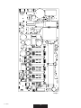
MOTORS BOARD
t108&34611-: 7-FE0O t 7-FE
t 7-FE
t 7%.9-FE
t%.9TJHOBM
Led flashing: the DMX signal is operating on the board
Led off:
check the U1 (6N137) and the DMX connecting cable (from PCB PAN IP)
t45&11&3.0503DIBOOFMOPUXPSLJOH JF:&--08 4XJUDIPGGUIFmYUVSFBOEEJTDPOOFDUUIF:&--08BOE$:"/DBCMFT
$POOFDUUIF:&--08DBCMFPOUIF$:"/DPOOFDUPS
3) Switch on the fixture:
B *GUIF:&--08NPUPSXPSLTOPSNBMMZJUJTOFDFTTBSZUPSFQMBDFUIF6 -
3b) If the motor is still not working check with extreme attention the motor and the interconnecting circuits (cables and
connectors). To check the cables and the motors you can measure the resistance as follows:
CFUXFFO1*/BOE1*/ PO*$6 S_PINCFUXFFO1*/BOE1*/ PO*$6 S_PIN
t*GUIFMFE 70150%.9JTPGG
%JTDPOOFDU50%*41-":1$#1"/*1DPOOFDUPSJGUIFMFEJTPODIFDL1$#1"/*1
2) Check U13 (78M05), L3, D6
t*GUIFMFE 7JTPGG
%JTDPOOFDU50%*41-":1$#1"/*1DPOOFDUPSJGUIFMFEJTPODIFDL1$#1"/*1
2) Check D4, L2, U12
t*GUIFMFE 7JTPGG
$IFDLJGUIFMFE 7JTPO JGJUJTPL
1a) Check if U11 is in thermal drift (ATTENTION on the heat dissipator there is dangerous tension!!!!)
C $IFDLJG6 6 6 6 6BSFJOTIPSUDJSDVJU4XJUDIPGGUIFmYUVSF3FNPWFBMMUIFDIJQTGSPNUIFTPDLFU
Switch on the fixture: if the led is on, insert the chips one by one in the sockets to find out which is in short-circuit.
1c) Check D3
1d) If all the operations described above have not given any positive result, change U11
*GUIFMFE 7JTPGGUPHFUIFSXJUIUIFMFE 7
B $IFDLUIF."*/108&3*/165XIFSFZPVDBONFBTVSFUIFXPSLJOHWPMUBHF
C $IFDLUIFNBJOGVTF JGJUJTCMPXODIFDL73 OPSNBMMZJUIBTBSFTJTUBODF∞). If it is in short circuit you must change it.
D $IFDL% #SJEHF3FDUJmFS JGJUJTPLDIFDL$
2d) If the fuse is still blown, change U11
rel. 7-0308
16
APPENDIX
tQBOJQt
tQBOJQ4t
17
rel. 7-0308
tDDJQt
rel. 7-0308
18
tDDJQ4t
19
rel. 7-0308
tDDJQt
rel. 7-0308
20
tDDJQ4t
21
rel. 7-0308
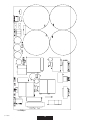
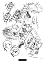
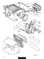
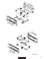
41"3&1"354 5&$)/*$"-%3"8*/(4
1"35*%*3*$".#*0 %*4&(/*5&$/*$*
rel. 7-0308
22
t"#"4&t
23
rel. 7-0308
t#)&"%t
rel. 7-0308
24
t#)&"%t
25
rel. 7-0308
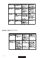
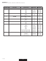
APPENDIX “A”
)FSFCFMPXZPVDBOmOEUIFDPNQMFUFMJTUPG%.9WBMVFT SFGQBHF
CHANNEL
FUNCTION
DESCRIPTION
DECIMAL
PERCENT
1
MOTOR SPEED
SPEED MOVEMENT
Slow
Mid1
Mid2
Fast
0..63
64..127
128..191
192..255
0%..24%
25%..50%
51%..74%
75%..100%
CONTINUOUSLY VARIABLE
White
Full color
0
255
0%
100%
CONTINUOUSLY VARIABLE
White
Full color
0
255
0%
100%
CONTINUOUSLY VARIABLE
White
Full color
0
255
0%
100%
CONTINUOUSLY VARIABLE
0%
100%
0
255
0%
100%
2
3
4
5
rel. 7-0308
CYAN
YELLOW
MAGENTA
DIMMER
6
BASIC COLORS/RAINBOW
Color mixing
Cyan
:FMMPX
Magenta
Blue
3FE
Green
Color mix sequence (slow)
Color mix sequence (mid)
Color mix sequence (fast)
0..25
26..51
52..77
78..103
104..129
130..155
156..181
182..207
208..233
234..255
0%..10%
10%..20%
20%..30%
30%..40%
40%..50%
50%..60%
60%..70%
70%..80%
80%..90%
90%..100%
7
REMOTE RESET/LAMP OFF
Normal
3FTFU EFMBZ
Normal
Lamp off (delay)
0..127
128..191
192..250
251..255
0%..50%
50%..75%
75%..98%
98%..100%
26
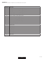
APPENDIX “B”
)FSFCFMPXZPVDBOmOEUIFDPNQMFUFMJTUPGUIFBWBJMBCMFHBNFT SFGQBHF
PROGRAM
FUNCTION
01
3FE.BHFOUB:FMMPXDPMPSNJYTFRVFODF TMPX
02
3FE.BHFOUB:FMMPX 8IJUFDPMPSNJYTFRVFODF TMPX
03
(SFFO$ZBO:FMMPXDPMPSNJYTFRVFODF TMPX
04
(SFFO$ZBO:FMMPX 8IJUFDPMPSNJYTFRVFODF TMPX
05
Blue Cyan Magenta: color mix sequence (slow)
06
Blue Cyan Magenta + White color mix sequence (slow)
07
All colors: color mix sequence (slow)
08
All colors + White color mix sequence (slow)
09
All colors: color mix sequence (mid)
10
All colors + White color mix sequence (mid)
11
All colors + white color mix sequence (mid+)
12
All colors - color mix sequence (mid+)
13
All colors + white color mix sequence (fast)
14
Basic color (fast)
15
Basic color + White (fast)
16
Wood (static)
17
Magenta (static)
18
3FE TUBUJD
19
-JHIU3FE TUBUJD
20
Orange (static)
21
:FMMPX TUBUJD
22
Cyan (static)
23
Light Cyan (static)
24
Green (static)
25
Light Green (static)
26
White (static)
27
Ten colors + White (slow)
27
rel. 7-0308
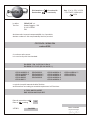
Dichiarazione
Declaration
La ditta:
The firm:
di conformità
of conformity
Doc. 316-1A REV 3 02/03
CITYCOLOR 1800W Ip54
02/03
STUDIO DUE s.r.l.
Strada Poggino, 100
01100 VITERBO
ITALY
dichiara sotto la propria responsabilità che il prodotto:
declare under our sole responsability that the product:
CITYCOLOR 1800W IP54
codice 0002
è conforme alle norme:
is in conformity with the standard:
EN 60598-1 Ed. VI (CEI 34-23 Ed. II)
EN 60598-2-17 Ed. II (CEI 34-38 Ed. II )
CEI EN 55013
CEI EN 55014-1
CEI EN 55013-1
CEI EN 55015
CEI EN 61000-3-2
CEI EN 61000-3-3
CEI EN 60065
CEI EN 55022
CEI EN 55011
CEI EN 61000-4-2
CEI EN 61000-4-4
CEI EN 61000-4-5
CEI EN 61000-4-6
CEI EN 61000-4-3
CEI EN 61000-4-11
CEI EN 55103-1
CEI EN 55103-2
e quindi ai requisiti essenziali delle Direttive:
and therefore according to essential requirement of Directives:
LV 73/23 AND 93/68 EEC
EMC 89/336 AND 93/68 EEC
Data di apposizione
Date of
marking
VITERBO,
:
:
03
04/02/03
FRANCO BERTINI
General Manager
Dichiarazione
Declaration
La ditta:
The firm:
di conformità
of conformity
Doc. 317-1A REV 3 02/03
CITYCOLOR 2500W Ip54
02/03
STUDIO DUE s.r.l.
Strada Poggino, 100
01100 VITERBO
ITALY
dichiara sotto la propria responsabilità che il prodotto:
declare under our sole responsability that the product:
CITYCOLOR 2500W IP54
codice 0003
è conforme alle norme:
is in conformity with the standard:
EN 60598-1 Ed. VII (CEI 34-23 Ed. II)
EN 60598-2-17 Ed. II (CEI 34-38 Ed. II )
CEI EN 55013
CEI EN 55014-1
CEI EN 55013-1
CEI EN 55015
CEI EN 61000-3-2
CEI EN 61000-3-3
CEI EN 60065
CEI EN 55022
CEI EN 55011
CEI EN 61000-4-2
CEI EN 61000-4-4
CEI EN 61000-4-5
CEI EN 61000-4-6
CEI EN 61000-4-3
CEI EN 61000-4-11
CEI EN 55103-1
CEI EN 55103-2
e quindi ai requisiti essenziali delle Direttive:
and therefore according to essential requirement of Directives:
LV 73/23 AND 93/68 EEC
EMC 89/336 AND 93/68 EEC
Data di apposizione
Date of
marking
VITERBO,
:
:
03
04/02/03
FRANCO BERTINI
General Manager
WARRANTY / GARANZIA
Warranty CARD
&RPSDQ\QDPH
0U0UV0LVV
$GGUHVV
7HORU(PDLO
'HDOHU
This page is intentionally left blank
This page is intentionally left blank
This page is intentionally left blank
Head Office: STUDIO DUE s.r.l. (I)
Str. Poggino, 100 - 01100 Viterbo (Italy)
tel. +39.0761.352520
fax +39.0761.352653
[email protected]
STUDIO DUE (UK)
3 Encon Court Owl Close
Moulton Park Industrial Estate
Northampton England UK - NN3 6 HZ
tel. +44.1933.650.820
[email protected]
STUDIO DUE Far East LTD (HK)
Unit 13 On 7th Floor, Heng Ngai Jewelry Centre,
4 Hok Yuen Street East
Hunghom, Kowloon, (Hong Kong)
tel. +852.29542141 fax +852.23302515
[email protected]
STUDIO DUE lighting technology (PRC)
Shen Zhen LTD (China)
www.studiodue.com
for technical info
[email protected]
Studio Due - ©
The features on this brochure are not binding: they can be changed without notice.
Le caratteristiche riportate su questo catalogo non sono impegnative: possono essere soggette a variazioni senza preavviso.