1
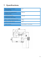
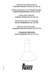
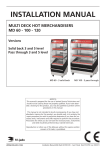
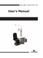
Notification
Dear Users,
Thank you for your purchase of RU 1000 Refraction Unit. Please take time to read our
user’s manual carefully before use.
This guarantees you to make full use of this unit and prolongs the operation life of
this unit.
Precautions
If you have detected abnormal heat, smoke, noise or smell, immediately stop using
the product.
In the event of an abnormality, turn off the power and disconnect the power plug from
the power socket. Continuing to use the product may result in electric shock or fire.
Observe the instructions given below regarding the power cable:
•
•
•
•
•
•
Be sure to use the supplied or specified power cable.
Do not modify, forcibly bend, kink or pull the power cable.
When disconnecting the power cable from the AC outlet, be sure to hold the cable
by the plug.
Pulling the cable may cause wire breakage or shot circuit, resulting in fire or electric
shock.
Do not connect or disconnect the plug of the power cable to/from the AC outlet
using wet hands.
Doing so may result in electric shock.
Do not touch the product with wet hands while the power cable is connected
to the AC outlet.
Doing so may result in electric shock.
If the product will not be used for a long period, disconnect the power cable
from the power source. Leaving the cable connected to the power socket for
a prolonged period will consume electricity and may result in heating.
Content
1.
Function Introduction .....................................................................................4
2.
Name of Parts ...............................................................................................4
3.
Installation .....................................................................................................5
4.
Attention ........................................................................................................8
5.
Operation ......................................................................................................8
6.
After-Service ................................................................................................10
7.
Specifications ..............................................................................................11
1. Function Introduction
The testing stand for ophthalmology with multifunction is one of a series of products
designed to meet customers requirements. lt is made of high quality in shape, firmness
in structure, convenience in maintenance and ease in operation, it is wear resistant and
corrosion proof. As one unit of a complete set of medical apparatus for ophthalmology,
it is an ideal choice for ophthalmologists and opticians not only in hospitals but also
in optic glass shops.
2. Name of Parts
1
7
2
8
3
4
9
5
10
11
6
1. Light source
5. Lift
9. Rotary Lever
2. Arm
6. Base
10. Drawer
3. Chair
7. Bracket
11. Support
4. TopPlate
8. Post tray
4
3. Installation
Please, open the packing box and check the packing list, then examine the parts
according to the packing list.
3.1
Installation of chair back (Fig. 1)
1. Remove M8 bolts form the support of handrails at left and right sides.
2. Remove stop bloke. Put the end of the fixed screw, which is in the low side
of the chair back, into the support of hand rail, then put the another end of the
fixed screw into it. Please put the screw in the center of the installation hole.
3. Insert the M8 bolts at the left and right sides and fasten then.
4. Install the covers for support of handrail.
Cover
Fixed screw
seat
Chair back
Stop block
Cylinder
Fig 1
5
3.2
Post (Fig. 2)
1. Open the power box and insert the plugs of wires into sockets according
to different colors.
2. Install the post and tighten the screws.
Post
Support
Scrow
Holes of
hanging
Fig 2
3.3
Parts of Post
1. Light Source (Fig. 3)
Put the wires in and insert the plugs of wires into the sockets
according to different colors.
Insert the iron tube and tighten the screw.
Iron tube
Screw
Light source fixer
Post
Fig 3
6
2. Projector Fixer (Fig. 4)
Projector Fixer base
Projector Fixer Lever
Screw
Fixer base
Screw
Lever
Fig 4
3.4
Arm (Fig. 5)
1. Insert the arm fixer into sleeve and tighten the screws
2. Insert the arm lock it up
Sleave
Arm
Screw
Fixer
Fig 5
7
4. Attention
1.
The A.C power source should be coincident to the local power source.Please,
check it before operation.
2.
There is an overheating protector for the motor. Once the overheating protector
works, the life of the chair can not rise up or descend down. After ten minutes,
the chair should work normally again.
3.
In order to prevent electrical leakage, keep the stand away from moisture and
water showing.
4.
It is dangerous to open the support or to repair the stand without cutting off the
power supply. Please, let professional undertake the repair work.
5.
Please, let the plug of the cable be out of the socket of the power source in case
the stand is out of operation for a long time.
6.
Please, let the plug of the cable be out of the socket of the power source in first,
then clean the stand surface with a soft mop wetted by a neutral cleaner. lt is
harmful to clean the stand with a piece of sandpaper, a bottle of ground power
and a cup of alcohol of other vaporizable impregnant etc.
5. Operation
1.
Please, insert the plug of the cable into the socket of the power source and turn
on the main switch in the underpart of the post.
2.
Control panel (Fig. 6)
“Down” chair
button
Main switch
“Up” chair
button
Slit lamp
switch
Proyecter
switch
Fig 6
Light source
switch
Indicator of
sliding table
8
3.
Push “On” button of “Power” switch, the indicator lights and indicates the power
supply is on.
Push “Off” button of “Power” switch, the indicator turns off indicates the power
supply is off.
4.
Use of the Chair
1. Push the “Up” chair button continuously so that the chair go up slowly; push
the “Down” chair button continuously so that the chair go down. There is
a limit switch for below the sliding table for preventing personal accidents.
2. The chair can be rotated horizontally to an angle of 90°. Please, loose the
locking lever the chair, then rotate the chair to an ideal angle, and lock it
up again.
3. It should be careful that operation of the chair for “Up” and “Down”can not
last continuously over on minute.
5.
Projector
1. There is a fixed socket on the upper part of the post for supplying power to
the projector.
2. On the control panel of the table, there is a control button for projector,
“On” and “Off”.
6.
Sliding Table
1. The sliding table is locked usually. Please loose the locking lever bellow the
table, then the table can slide horizontally.
2. The table can be rotated horizontally round the support to an angle of 90.
There is a mechanic limiting component. Please, loose the locking lever on
the support, the rotate the table to an ideal angle and lock it up again.
3. On the both sides of the table is a DC socket (3V-12V) for supplying power
to the crevice light. Please, open the control panne, there is a “Aux” button
for controlling slit lamp.
4. Below the sliding table,there is a socket for supplying power for the sight tester.
9
7.
Arm
1. Loose the fixer of the arm and adjust the level of the arm on the post.
2. Loose the locking lever of the arm, then the arm be rotated around the fixer
and the micro-adjustment of the vertical position of the sight disc is possible.
Then adjust it to an ideal position, and lock it up again.
3. Use the round lever of the arm to do the micro-adjustment of the sight disc.
6. After-Service
1.
We offer one year warranty on the product from the date written in the invoice,
but the following cases are exclusive.
1. Disassembly and repair made by customers themselves.
2. Damage caused in transport and store or by an unsuitable power souce and
wrong voltage.
3. Wrong operation or disobedience to the operation manual of our products.
2.
Please, in term of the users’ manual to use our product. If there is something
wrong, let the plug of thecable be out of the power source immediately and
contact with the local agents.
10
7. Specifications
Max. Angle for Rotation
of Sliding Table
9-0°
Distance for Displacement
of Sliding Table
360mm
Distance for Stroke
of Electrical Driven Chair
160mm
Max. Loading Capacity of Arm
10kg
Power of Light Source
18w
Power Source
AC220V(AC110V) 50Hz
11
LUXVISION is not responsible or liable for indirect, special or consequential damages arising out of or in
connection with the use or performance of the product or damages with respect to any economic loss,
loss of property, loss of revenues or profits, loss of enjoyment or use, costs of removal or installation or
other consequential damages of whatsoever nature. Some states do not allow the exclusion or limitation
of incidental or consequential damages. Accordingly, the above limitation may not apply to you.
Every effort has been made to ensure the accuracy of this manual. However, LUXVISION, makes no
warranties with respect to the documentation and disclaims any implied warranties of merchantability
and fitness for a particular purpose. LUXVISION, Inc. shall not be liable for any errors or for incidental or
consequential damages in connection with the furnishing, performance, or use of this manual or the examples
herein. The information in this document is subject to change without notice.
12