1
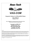
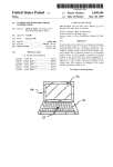
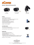
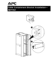
Cabinet Supported Aisle Roof Containment Solution Userʼs Manual Version 2.0 December 2013 Polargy 256 Gibraltar Drive, Suite 106 Sunnyvale, CA 94089 1.888.813.8338 Aisle Roof Containment Manual, Rev 2.0 December 2013 Contents INTRODUCTION page 3 AISLE CONTAINMENT POLARPLEXTM P2 SLIDING DOOR pages 4 - 19 CABINET SUPPORTED POLARPLEXTM DROP-AWAY ROOF CONTAINMENT SYSTEM pages 20 - 25 CABINET SUPPORTED POLARPLEXTM STANDARD PANEL CONTAINMENT SYSTEM pages 26 - 30 Polargy, Inc.! ! 2 Aisle Roof Containment Manual, Rev 2.0 December 2013 INTRODUCTION This document is the User’s Manual for Polargy’s PolarPlex Cabinet Supported Aisle Roof Containment Systems. Aisle Roof Containment User Manual Legal Information The information contained in this guide is subject to change without notice. Polargy shall not be liable for technical or editorial errors or omissions contained herein; nor is it liable for any injury, loss, or incidental or consequential damages resulting from the furnishing, performance, or use of this material and equipment. Warranty Polargy guarantees manufactured products and each part or component thereof against all defects in material and/or workmanship. Polargy agrees to remedy any manufacturing defect either through replacement or repair at no charge provided that the defective unit is returned, transportation prepaid, to Polargy with a Return Material Authorization. The warranty extends for a period of one year from the date of installation or initial use, provided that this period shall not exceed 18 months from the original date of shipment from Polargy. Any product that has been repaired or replaced shall be similarly warranted on its repair or replacement for the remaining product warranty period or 90 days from the date of repair or replacement, whichever expires last. This warranty does not extend to products that have been subjected to neglect, accident or improper use, nor to units that have been altered by non-Polargy personnel. No warranties other than those set forth in this section are given or implied with respect to the products furnished. Polargy shall, in no event, be liable for consequential damages, for loss, damage or expense directly or indirectly arising from the use of the products, for any inability to use materials or from any other cause. Polargy, Inc.! 3 Aisle Roof Containment Manual, Rev 2.0 December 2013 AISLE CONTAINMENT POLARPLEXTM P2 SLIDING DOOR INTRODUCTION TO THE POLARPLEXTM P2 SLIDING DOORS The PolarPlexTM P2 Sliding Doors from Polargy are an adjustable height aisle end containment door. Height adjustments are made by extending the vertical support legs and by adjusting the bottom section of the door itself. Adjustable height side Extender Panels are available for aisles greater than 54” in width. These side extenders increase the aisle width coverage up to 103”. The door systems are designed to be compatible with any brand of rack that is between 42U minimum and 50U maximum height (79” – 89”). Doors are available in three sliding options including: double-door, single-door lefthand sliding and single-door right-hand sliding. Doors are finished in flat black with anodized aluminum trims. The doors can be installed onto slab floors or raised access floors. All doors include full- height, twin-wall polycarbonate inserts, an automatic close system, and an optional magnetic hold-open catch. P2 Sliding Door with Extender Panels Polargy, Inc.! 4 Aisle Roof Containment Manual, Rev 2.0 December 2013 SAFETY INFORMATION WARNING: Improper use or installation of the Aisle Containment Sliding Doors may lead to serious injury or death. Read and understand all instructions for proper installation and use of this product. Installation of Aisle Containment Doors may require the use of ladders, scaffolds, and other climbing tools. Follow all climbing device procedures and observe standard safety precautions. The Aisle Containment Door components are heavy and large. This requires that at least two personnel be used for assembly and installation. Obtain adequate assistance or hire professional equipment riggers. INTENDED USE Install the doors only in a restricted service environment, such as a data center. Use indoors only, in environmentally controlled areas; do not use outdoors, in harsh environments, or in air-handling spaces. Not for use in plenums. STORAGE OF SLIDING DOORS Aisle Containment Sliding Doors should be stored indoors only in environmentally controlled areas. Do not store outdoors. Do not expose to harsh or humid areas. TOOLS REQUIRED FOR INSTALLATION • • • • 5/32” hex wrench for flange button heads screws and flat head screws 1/8” hex wrench for set screws Small philips head screwdriver for adjustable door and extender panel screws Drill and other tools for making floor and rack attachments Polargy, Inc.! 5 Aisle Roof Containment Manual, Rev 2.0 December 2013 Component Overview The sliding door assembly comes boxed and is comprised the following basic components: 1. Horizontal Header Track Assembly (2 pieces) 2. Vertical Support Posts (2 posts) 3. Coupler 4. Sliding Door Assemblies (2 doors) 5. Hardware Kit (Roller guides, gaskets, brush grommet, brackets, screws) The Extender Panels are comprised the following basic components: 1. Adjustable Height Panels (2 pieces) 2. Gap Filler Gasket 3. Hardware Kit (screws, brackets) Polargy, Inc.! 6 Aisle Roof Containment Manual, Rev 2.0 December 2013 Installa6on Steps 1) Connect the two Header Track Assemblies with the Coupler using flange bu:on head screws and washers. Exploded Header Tracks and Coupler Important: Install the top four screws first. One Header Track with Coupler Polargy, Inc.! 7 Aisle Roof Containment Manual, Rev 2.0 December 2013 2) Install Cap Plugs into unused header holes. Completed Header Track Assembly Polargy, Inc.! 8 Aisle Roof Containment Manual, Rev 2.0 December 2013 3) Set The Height of the VerCcal Support Posts The verCcal support posts are shipped in the lowest posiCon which gives an inside frame opening height of 78.9” and an external frame height of 82.5”. Adjust the verCcal support footer to create the desired height. Make sure the rubber stops on the VerCcal Support Posts are facing inward when they a:ached to the Header Track. Polargy, Inc.! 9 Aisle Roof Containment Manual, Rev 2.0 December 2013 4) A:ach the VerCcal Support Posts to the Header Track. (This is a two man job) The header needs to be Clted about 45 degrees, then slide the verCcal posts parCally into the header sides, then Clt the header back flat and push the posts in the remaining inch or so. Then secure with flange bu:on head screws. (Another alternaCve is to remove the Header Track face plate, install the VerCcal Posts, then re-‐a:ached the face plate.) #1 Tilt Header #2 Slide Posts Par6ally On #3 Tilt Header Back Flat, Push Posts In Polargy, Inc.! 10 Aisle Roof Containment Manual, Rev 2.0 December 2013 5) If Extender Panels are being used, adjust the height of the panels to match the height of the top of the Header Track. Extender Panel Behind Header Track 6) A:ach the Header Track Assembly/VerCcal Support Posts to the Racks with the brackets. NOTE: If Extender Panels are being installed, place the Header Track/VerCcal Posts temporarily offset from the racks by about 2”. Next, slide the Extender Panels into place, then push the enCre assembly flush against the racks. Last, secure the Extender Panels to the Header, then the Header to the racks. Extender Panels AIach at Top with Two Brackets Polargy, Inc.! 11 Aisle Roof Containment Manual, Rev 2.0 December 2013 NOTE: A:ach Gap Filler Gasket between the Extender Panels. Gasket a:aches to back of Header Track. Gasket Shown in Purple but is Black 7) Secure the VerCcal Support Post feet to the floor with hardware (not provided) as needed for the floor type and condiCons. Hole diameter is 9/16”. Polargy, Inc.! 12 Aisle Roof Containment Manual, Rev 2.0 December 2013 8) Secure the Roller Guide to the floor. Place the roller guide inline with the door center-‐line and at 26” from the inside verCcal post to the center to the roller. If floor is not level, guide may require shimming to insure roller engages bo:om of door track. Polargy, Inc.! 13 Aisle Roof Containment Manual, Rev 2.0 December 2013 NOTE: If the Extender Panels are being installed, then place the Roller Guide at the inside edge of the flange on the bo:om of the Extender Panel. Polargy, Inc.! 14 Aisle Roof Containment Manual, Rev 2.0 December 2013 9) Adjust the height of the doors. The door is delivered in the shortest se`ng. To extend the door, simply remove the screws, slide the bo:om piece to the desired locaCon and re-‐a:ach the screws. Polargy, Inc.! 15 Aisle Roof Containment Manual, Rev 2.0 December 2013 10) A:ach the Doors to the Header. Match the door slots to the carriage hooks; place the door onto the hooks while simultaneously posiConing bo:om door gap over roller. Confirm the door slides back and forth smoothly. Polargy, Inc.! 16 Aisle Roof Containment Manual, Rev 2.0 December 2013 11) Level, if necessary, with set screw using 1/8” hex wrench. 12) Secure with bu:on head screw using 5/32” hex wrench. Polargy, Inc.! 17 Aisle Roof Containment Manual, Rev 2.0 December 2013 13) A:ach Seal Gaskets A:ach the gaskets to the inside edge of the doors. Select one door and run gasket runs the enCre length of door. On the opposite door, run the gasket only between the upper and lower secCons as shown below. Cut to size with scissors. Polargy, Inc.! 18 Aisle Roof Containment Manual, Rev 2.0 December 2013 14) A:ach Brush Grommets The strip brush grommet runs 5’ and is a:ached to door starCng just below the top head piece of the door. The brush grommet is a:ached with self tapping screws in the posiCon as shown below. Polargy, Inc.! 19 Aisle Roof Containment Manual, Rev 2.0 December 2013 CABINET SUPPORTED POLARPLEXTM DROP-AWAY ROOF CONTAINMENT SYSTEM INTRODUCTION TO THE POLARPLEXTM ROOF AISLE CONTAINMENT SYSTEM The PolarPlexTM Drop-Away Panels a Roofing Option for an Aisle Containment System. These unique panels are attached to the cabinets and are deployed horizontally across the aisles to create a tight containment barrier. The panels are made of an aluminum frame with a special translucent insert. The panels are UL-listed for use below sprinkler heads and the inserts are heat sensitive and promptly move out of their setting in high heat. The panels are custom sized for each installation. SAFETY INFORMATION WARNING: COLD AISLE CONTAINMENT ROOF PANELS ARE DESIGNED TO BE SECURELY ATTACHED TO THE ROOF STRUCTURE OF THE INSTALLED CABINETS. DO NOT LEAVE ASSEMBLY UNSECURED TO CABINETS. CABINETS MUST BE STABILIZED PRIOR TO AISLE CONTAINMENT ROOF SYSTEM ASSEMBLY. CAUTION SHOULD BE EXERCISED TO ENSURE THE CABINET LOAD RATING IS NOT EXCEEDED. INTENDED USE Drop-Away Roof Panels are for use only in a restricted service environment, such as a data center. Use indoors only, in environmentally controlled areas; do not use outdoors, in harsh environments, or in air-handling spaces. Not for use in plenums. STORAGE OF DROP-AWAY ROOF PANELS Aisle Containment Drop-Away Panels should be stored indoors only in environmentally controlled areas. Do not store outdoors. Do not expose to high temperatures. Polargy, Inc.! 20 Aisle Roof Containment Manual, Rev 2.0 December 2013 INSTALLING THE DROP-AWAY ROOF PANEL SYSTEM Component Overview The Drop-Away Roof Panel System is comprised the following basic components: 1. Drop-Away Panels (Sized to project) 2. Aluminum L-Angle for Panel Shelf (2 sets, one for each side of aisle) 3. P1000 Unistrut (provided by others) 4. Miscellaneous nut and bolt hardware (provided by others) Polargy, Inc.! 21 Aisle Roof Containment Manual, Rev 2.0 December 2013 Basic Supporting Framework Design 1) The Drop-Away Panels are supported by a two piece framework of an Aluminum L-Angle (the shelf) attached to Unistrut which is attached to the tops of the cabinets. 2) The 1.5” x 1.5” Aluminum L-Angle is bolted to the P1000 Unistrut 3) The L-Angle is bolted flush to the top of the Unistrut channel so that there is a small 0.125” gap below the L-Angle so that it does not interfere with the cabinet door. 4) This L-Angle/Unistrut combination is bolted to the tops of the cabinets. Polargy, Inc.! 22 Aisle Roof Containment Manual, Rev 2.0 December 2013 Determining the Supporting Frame Layout 1) Drop-Away Panel Length, previously determined, is used to set the spacing between rows of the P1000 Unistrut/Panel Shelf L-Angle. 2) Add 1.0” to the length of the panel to determine the distance between inside edges of the P1000 Unistrut. 3) For example, if the panels are 54.0” long, then set the distance between the inside edges of the P1000 Unistrut at 55.0”. Polargy, Inc.! 23 Aisle Roof Containment Manual, Rev 2.0 December 2013 Installing the Supporting Frame 1) Attach the P1000 Unistrut to the tops of the cabinets. Sometimes, existing cabinet top holes can be used, other times new holes may need to be drilled. 2) Attach the Aluminum L-Angle to the Unistrut such that there is a 1/8 gap below the bottom of the L-Angle. Polargy, Inc.! 24 Aisle Roof Containment Manual, Rev 2.0 December 2013 Installing the Drop-Away Panels 1) The Drop-Away Panels are simply lifted into place and set onto the L-Angle shelves. 2) The Drop-Away Panels rest on the horizontal edge of the L-Angles and are captured by the vertical edges of the L-Angles so that they do not fall out. 3) Optional 3M Dual Lock tabs are available to further secure the panels. Polargy, Inc.! 25 Aisle Roof Containment Manual, Rev 2.0 December 2013 CABINET SUPPORTED POLARPLEXTM STANDARD PANEL CONTAINMENT SYSTEM INTRODUCTION TO THE POLARPLEXTM STANDARD PANELS The PolarPlexTM Standard Containment Panels are deployed vertically, either above the cabinets or next to the cabinets to seal off empty rack spaces. The panels are made of an aluminum frame with a twin-wall polycarbonate insert. The panels are custom sized for each installation. SAFETY INFORMATION WARNING: VERTICAL CONTAINMENT PANELS ARE DESIGNED TO BE SECURELY ATTACHED TO THE ROOF STRUCTURE OF THE INSTALLED CABINETS OR TO THE FLOOR. DO NOT LEAVE PANELS UNSECURED ON THE CABINETS. CABINETS MUST BE STABILIZED PRIOR TO INSTALLATION OF THE STANDARD PANELS. CAUTION SHOULD BE EXERCISED TO ENSURE THE CABINET LOAD RATING IS NOT EXCEEDED. INTENDED USE Standard Panels are for use only in a restricted service environment, such as a data center. Use indoors only, in environmentally controlled areas; do not use outdoors, in harsh environments, or in air-handling spaces. Not for use in plenums. STORAGE OF STANDARD PANELS Aisle Containment Standard Panels should be stored indoors only in environmentally controlled areas. Do not store outdoors. Polargy, Inc.! 26 Aisle Roof Containment Manual, Rev 2.0 December 2013 INSTALLING THE POLARPLEXTM STANDARD PANELS Component Overview The Standard Containment Panel System is comprised the following basic components: 1. Standard Panels (Sized to project) 2. Aluminum F-Channel for bottom of panels 3. 3M Dual Lock tabs 4. Miscellaneous securing hardware for F-Channel (provided by others) 5. P1000 Unistrut and standard Unistrut hardware as needed (provided by others) Polargy, Inc.! 27 Aisle Roof Containment Manual, Rev 2.0 December 2013 Basic Supporting Framework Design 1) There is an existing two piece framework of an Aluminum L-Angle and Unistrut on the cabinet tops that supports the Drop-Away Roof Panels. 2) This Unistrut framework serves as the upper support of the Standard Panels, along with the floor F-Channel and 3M Dual Lock. 3) For 24” to 96” empty sections between racks, the support of the adjacent cabinets is sufficient to hold the Unistrut. 4) For empty sections beyond 96”, then additional vertical Unistrut is added. 5) The brackets for the vertical Unistrut should be in line with the horizontal Unistrut so that there is a clear mounting surface for the Standard Panels. Polargy, Inc.! 28 Aisle Roof Containment Manual, Rev 2.0 December 2013 Installing the Vertical Unistrut to the Horizontal Unistrut 1) On the bottom attach two standard 90-degree brackets to the vertical P1000 Unistrut such that the brackets are in line with the horizontal Unistrut roof support. 2) At the top attach two standard 90-degree brackets to the vertical P1000 Unistrut such that the brackets are in line with the horizontal Unistrut roof support. Polargy, Inc.! 29 Aisle Roof Containment Manual, Rev 2.0 December 2013 Installing the PolarPlexTM Standard Panels 1) Secure the F-Channel to the floor in a position such that the channel is aligned to the outside edge of the horizontal Unistrut above. 2) Add two 3M Dual Lock Tabs to the two upper corners of the Standard Panel. 3) Insert the bottom of the Standard Panel into the F-Channel. 4) Press the top of the Standard Panel against the horizontal Unistrut/3M Dual Tabs to secure it in place. Polargy, Inc.! 30 Aisle Roof Containment Manual, Rev 2.0 December 2013 Polargy Contact Information Phone: Website: Email: Polargy, Inc.! 1.888.816.8338 www.polargy.com [email protected] 31