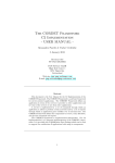
1
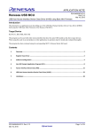
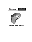
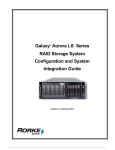
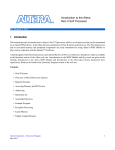
AN10904
USB HID with the LPC1300 on-chip driver
Rev. 01 — 15 January 2010
Application note
Document information
Info
Content
Keywords
LPC1300, USB, HID, On-Chip Driver, ROM, Cortex-M3, LPC-LINK,
LPCXpresso, IAR LPC1343-SK, Keil MCB1000
Abstract
This application note explains how to use the on-chip USB drivers in the
LPC1300 Cortex-M3 based microcontroller to implement a simple USB
Human Interface Device (HID).
AN10904
NXP Semiconductors
USB HID with the LPC1300 on-chip driver
Revision history
Rev
Date
Description
01
20100115
Initial revision.
Contact information
For additional information, please visit: http://www.nxp.com
For sales office addresses, please send an email to: [email protected]
AN10904_1
Application note
© NXP B.V. 2010. All rights reserved.
Rev. 01 — 15 January 2010
2 of 24
AN10904
NXP Semiconductors
USB HID with the LPC1300 on-chip driver
1. Introduction
The LPC1300 microcontroller family is based on the ARM Cortex-M3 CPU architecture
for embedded applications featuring a high level of support block integration and low
power consumption. The peripheral complement of the LPC1300 series includes up to
32 kB of flash memory, up to 8 kB of data memory, USB Device interface, 1 UART, 1
SSP controller, SPI interface, 1 I2C interface, 8 channel 10-bit ADC, 4 general purpose
timer/PWMs, and up to 40 general purpose I/O pins.
Also present is 16 kB of ROM. The on-chip ROM contains a bootloader supporting UART
and USB flash programming, as APIs for user firmware in flash. The flash API
implements a simple interface to the on-board flash programming functionality. The USB
API supports development of Human Interface Devices (HID) and Mass Storage Class
(MSC) devices.
The various topics covered in this application note are as follows:
• USB overview
• On-chip USB driver features
• On-chip USB driver setup
• Using the usdhidrom example
2. On-chip USB driver features
The on-chip USB driver is incorporated in the LPC1300 family’s on-chip ROM. It
facilitates building simple USB devices while saving flash memory. The LPC1300 family
on-chip USB driver implements both HID and MSC devices. The ROM driver functionality
is simplified and easy to use.
The HID class driver is useful for communicating a moderate amount of data (less than
64 kB per second) to a USB host. It supports interrupt transfers which allow the device to
be polled by the PC host. The MSC class driver implements a disk drive which can
accept file reads and writes from a host USB device.
Table 1.
On-chip USB driver features
Feature
ROM HID Driver
ROM MSC Driver
Interrupt Transfers (Data
“Pushed” to PC)
Yes
No
Endpoints
Control, 1 in, 1 out
Control, 1 in, 1 out
Real-time Data Transfers
Yes
No
File read/write
No
Yes
Supported clock
12 MHz external crystal[1]
12 MHz external crystal[1]
RAM Usage
First 384 bytes
First 384 bytes + Storage
[1]
A 12 MHz external crystal or a high-accuracy USB ceramic resonator is required to meet the USB 2.0
frequency tolerance specifications which are 12 Mbps 12.000 Mb/s ±0.25 % (2,500 ppm).
See the LPC1300 User’s Manual section titled “USB driver functions” for a detailed
description of the USB driver functions including clock and pin initialization, USB
peripheral initialization, USB connect, and the USB interrupt handler.
AN10904_1
Application note
© NXP B.V. 2010. All rights reserved.
Rev. 01 — 15 January 2010
3 of 24
AN10904
NXP Semiconductors
USB HID with the LPC1300 on-chip driver
This application note describes the HID driver in detail. Refer to application note
AN10905 for a description of the MSC driver.
3. On-chip USB driver setup
A few steps are required to use the on-chip USB driver. The following information is not
comprehensive and is intended to be used as a supplement to the User’s Manual chapter
10 section titled “4.2 USB human interface driver.”
3.1 RAM allocation
The on-chip USB driver requires RAM from 0x10000050 and 0x10000180 to be allocated
for USB frame buffers. The method to allocate this RAM depends on the particular
development environment, but will usually involve modifying a linker script and changing
the address ranges for data placement. Because linkers are often not designed with
smart placement algorithms that work with tiny segments of memory, we recommend
leaving the RAM from 0x10000000 through 0x10000050 unallocated as well. This is
shown in Fig 1 and the following sections describe the steps required for setting up the
linker in Keil, IAR and LPCXpresso environments.
AN10904_1
Application note
© NXP B.V. 2010. All rights reserved.
Rev. 01 — 15 January 2010
4 of 24
AN10904
NXP Semiconductors
USB HID with the LPC1300 on-chip driver
LPC1311
LPC1313
LPC1342
LPC1343
1311/42
LPC1313/43
LPC1342
LPC1313/43
1311
Fig 1. LPC1300 memory map
3.1.1 LPCXpresso by Code Red
LPCXpresso normally generates linker scripts automatically to match the memory map of
the currently selected LPC microcontroller. To customize the linker script, LPCXpresso
must be configured not to regenerate the linker scripts.
1. First, create and build a project. This will create the standard linker scripts
matching the selected LPC1300 part memory configuration. The linker scripts will
have an .ld extension. They will be generated into the project\build configuration
directory, or usbhidrom\Debug.
2. Save the standard linker scripts by renaming them (we chose the name
“lpc1343_romusb_buffer”) and moving them into a project subdirectory to
distinguish them from the LPCXpresso tools’ automatically generated scripts. We
chose to put them in a subdirectory called “lpcxpresso_tool” to help distinguish
them from Keil and IAR development tool files.
3. Modify the lpc1343_romusb_buffer_mem.ld script to exclude 0x10000000
through 0x10000180 from the memory map. The areas to be changed (RamLoc8
AN10904_1
Application note
© NXP B.V. 2010. All rights reserved.
Rev. 01 — 15 January 2010
5 of 24
AN10904
NXP Semiconductors
USB HID with the LPC1300 on-chip driver
line) for the specific case of the LPC1343 are highlighted below.
MEMORY
{
/* Define each memory region */
MFlash32 (rx) : ORIGIN = 0x0, LENGTH = 0x8000 /* 32k */
RamLoc8 (rwx) : ORIGIN = 0x10000180, LENGTH = 0x1E80 /*
8k */
}
4. Modify the master linker script include paths. There are typically three linker
scripts, usb_buffer_lib.ld, a usb_buffer_mem.ld, and a usb_buffer.ld. Modify the
lpc1343_romusb_buffer.ld script’s INCLUDE lines to correct the paths to
lpc1343_romusb_buffer_lib.ld and lpc1343_romusb_buffer_mem.ld as shown
below.
* (created from nxp_lpc13_c.ld (v3.0.6 (200911181345)) on
Fri Nov 20 17:14:35 PST 2009)
*/
INCLUDE "../lpcxpreso_tool/lpc1343_romusb_buffer_lib.ld"
INCLUDE "../lpcxpreso_tool/lpc1343_romusb_buffer_mem.ld"
ENTRY(ResetISR)
SECTIONS
{
…
5. Configure LPCXpresso to use the modified linker scripts. This is set up in the
Project Properties dialog under C/C++ Build Settings. Now make sure the Tool
Settings tab is selected. Then select MCU Linker Target. Uncheck “Manage
linker script” and put the linker script path into the Linker script text field. The
path should be relative to the project Debug or Release output directories and it
should point to the master linker script, which is the one without _lib or _mem in
its name. In this case, lpc1343_romusb_buffer_mem.ld.
AN10904_1
Application note
© NXP B.V. 2010. All rights reserved.
Rev. 01 — 15 January 2010
6 of 24
AN10904
NXP Semiconductors
USB HID with the LPC1300 on-chip driver
Fig 2. LPCXpresso project properties linker script settings
3.1.2 IAR Embedded Workbench IDE 5.4
IAR projects typically already reference a part-specific linker script. The path to this linker
script can be found in the Project Options dialog, under the Linker category, “Config” tab.
To allocate the RAM region for the on-chip USB driver, click “Edit” in the Project Options
dialog. Use the “Memory Regions” tab in the “Linker configuration file editor” to modify
the RAM region start address to 0x10000180.
AN10904_1
Application note
© NXP B.V. 2010. All rights reserved.
Rev. 01 — 15 January 2010
7 of 24
AN10904
NXP Semiconductors
USB HID with the LPC1300 on-chip driver
Fig 3. IAR Embedded Workbench project options linker script settings
3.1.3 Keil µVision4 RealView MDK-ARM
In Keil µVision4, use the Target tab in the Project Options dialog to change the RAM
region. Set the start address to 0x10000180 and reduce the size by 0x180.
AN10904_1
Application note
© NXP B.V. 2010. All rights reserved.
Rev. 01 — 15 January 2010
8 of 24
AN10904
NXP Semiconductors
USB HID with the LPC1300 on-chip driver
Fig 4. Keil µVision4 RealView MDK-ARM target options linker script settings
3.2 ROM initialization
The LPC1300 on-chip ROM always executes at reset. This is key for the chip to start up
in a known state. It is important to make sure that the on-chip ROM is allowed to execute
before user code when you are developing code with a debugger. This is typically
ensured by use of a debugger macro or script file. Most LPC1300 development tools ship
with compatible debugger macros that ensure the ROM runs at startup. If you have any
questions about this, ask your development tool provider.
3.3 Calling on-chip USB driver functions
The USB driver has an API with three functions and an interrupt handler. They are called
through a jump table located in ROM. The jump table location may change as the ROM
is improved on newer products, so it is accessed through a pointer at a fixed address. To
access these functions, it is necessary to declare the jump table entries and a pointer-tothe-pointer to the jump table. Fig 5 shows the pointer setup.
AN10904_1
Application note
© NXP B.V. 2010. All rights reserved.
Rev. 01 — 15 January 2010
9 of 24
AN10904
NXP Semiconductors
USB HID with the LPC1300 on-chip driver
USB Driver
0x1fff1ff8
init_clk_pins
Ptr to ROM Driver Table
isr
init
connect
ROM Driver Table
Ptr to USB Driver Table 1
Ptr to Device Table 2
Device 2
Ptr to Function 1
Ptr to Function 2
Ptr to Device Table 3
Ptr to Function 3
…
…
Ptr to Device Table n
Ptr to Function n
Fig 5. ROM layout for API calls
The following C code can be used.
typedef struct _USBD {
void
(*init_clk_pins)(void);
void
(*isr)(void);
void
(*init)( USB_DEV_INFO * DevInfoPtr );
void
(*connect)(uint32_t con);
} USBD;
typedef struct _ROM {
const
USBD * pUSBD;
} ROM;
ROM ** rom = (ROM **)0x1fff1ff8;
To call one of the functions, syntax like that below could be used. This code
dereferences the jump table location for the USB device driver at 0x1fff1ff8, then
uses the jump table to call into the USB driver init_clk_pins() function.
(*rom)->pUSBD->init_clk_pins();
3.4 Configuring the USB driver interrupt
The on-chip USB uses an interrupt to respond to events generated by the USB controller
in the LPC1300. The USB interrupt is in the Cortex interrupt vector table which starts at
0x00000000. When this interrupt is received by the application code, it must be passed
on to the interrupt handler in the USB driver in ROM.
On the LPC1300, user code is compiled to run out of Flash at 0x00000000. By default,
upon reset, the on-chip ROM is mapped to 0x00000000 instead of Flash. When the
microcontroller’s ROM-based initialization code has completed, then the memory is
AN10904_1
Application note
© NXP B.V. 2010. All rights reserved.
Rev. 01 — 15 January 2010
10 of 24
AN10904
NXP Semiconductors
USB HID with the LPC1300 on-chip driver
remapped so that flash memory starts at 0x00000000 and the ROM containing the USB
driver starts at 0x1FFF1000. At this point, when the memory at 0x00000000 is
remapped, control of interrupts is transferred from ROM to user flash memory.
To ensure that the ROM USB interrupt handler is called, an interrupt must be declared in
the user code that calls the ROM interrupt handler. When using the industry-standard
CMSIS headers for Cortex, the interrupt handler should look like the code below,
regardless of which development tool is used.
USB_IRQHandler(void)
{
(*rom)->pUSBD->isr();
}
3.5 Configuring USB driver data structures
To use the on-chip USB driver in Human Interface Device mode, a few structures must
be set up. A USB_DEV_INFO must be declared. Its DevType member needs to be
initialized to USB_DEVICE_CLASS_HUMAN_INTERFACE and its DevDetailPtr member
needs to point to an HID_DEVICE_INFO structure. In the HID_DEVICE_INFO structure,
the StrDescPtr must be initialized to point to the USB String Descriptor for your device.
Most importantly, functions to accept and return data to be communicated with the host
must be defined and HID_DEVICE_INFO must be initialized to point to them.
For more detail on all of these structure fields, see the User’s Manual chapter titled USB
on-chip driver.
3.5.1 USB_DEVICE_INFO initialization
To specify that we plan to initialize the driver for Human Interface Device mode, we set
DevType. DevDetailPtr points to a HID_DEVICE_INFO structure with HID-specific
configuration fields.
DeviceInfo.DevType = USB_DEVICE_CLASS_HUMAN_INTERFACE;
DeviceInfo.DevDetailPtr = (uint32_t)&HidDevInfo;
3.5.2 HID_DEVICE_INFO initialization
The HID_DEV_INFO structure contains information needed to configure the on-chip
driver to implement a Human Interface Device USB peripheral. Some key fields to
initialize are the Vendor ID and Product ID and the string descriptor.
HidDevInfo.idVendor = USB_VENDOR_ID;
HidDevInfo.idProduct = USB_PROD_ID;
HidDevInfo.StrDescPtr = (uint32_t)&USB_StringDescriptor[0];
Two functions are needed to send and receive data to the host. The InReport and
OutReport function pointers in HID_DEVICE_INFO structure must be initialized to
point to these functions so that the on-chip USB driver is able to call those functions and
transfer the data.
HidDevInfo.InReport = GetInReport;
HidDevInfo.OutReport = SetOutReport;
3.5.3 USB string descriptor initialization
A String Descriptor is an array of 2-byte characters that provides human-readable text
that can facilitate the device identification and install process. String Descriptors use 2byte characters in Unicode format to allow representation of many languages worldwide.
Review the USB specification for more details on the String Descriptor format.
AN10904_1
Application note
© NXP B.V. 2010. All rights reserved.
Rev. 01 — 15 January 2010
11 of 24
AN10904
NXP Semiconductors
USB HID with the LPC1300 on-chip driver
/* USB String Descriptor (optional) */
const uint8_t USB_StringDescriptor[] = {
/* Index 0x00: LANGID Codes */
0x04,
/* bLength */
USB_STRING_DESCRIPTOR_TYPE,
/* bDescriptorType */
WBVAL(0x0409), /* US English */
/* wLANGID */
/* Index 0x04: Manufacturer */
0x1C,
/* bLength */
USB_STRING_DESCRIPTOR_TYPE,
/* bDescriptorType */
'N',0,
'X',0,
'P',0,
' ',0,
'S',0,
'E',0,
'M',0,
'I',0,
'C',0,
'O',0,
'N',0,
'D',0,
' ',0,
…
3.6 Call setup functions
In addition to the setup above, this small section lists the actual calls that need to be
completed to initialize the on-chip USB driver. For more detail, examine the example
project.
1. Enable 32-bit Timer 1.
Timer32 1 is used by the ROM driver for internal timing and cannot be used by
the application program.
2. Call init_clk_pins();
3. Call init();
4. Call connect();
AN10904_1
Application note
© NXP B.V. 2010. All rights reserved.
Rev. 01 — 15 January 2010
12 of 24
AN10904
NXP Semiconductors
USB HID with the LPC1300 on-chip driver
4. Using the usbhidrom example
This application note describes how to run the sample HID application using several
combinations of hardware and software. Please note that three example software
workspaces have been provided: NXP’s LPCXpresso, IAR, and Keil tools. Although the
C code is the same, each workspace has been customized to easily open in the specific
IDE it is targeted for, and also to control an LED on the specific board it was intended to
run on. These tool combinations are listed in Table 2. If other combinations of tools are
used (for example, using the IAR EWARM suite with the Keil MCB1000), then the
usbhidrom example code may need to be configured by modifying config.h to specify
which I/O pins to monitor and control.
Table 2.
Tool combinations
Software suite
JTAG probe
Target board
LPCXpresso by Code Red
LPC-LINK integrated on
LPCXpresso board
LPCXpresso board and
Embedded Artists LPCXpresso
baseboard
LPCXpresso by Code Red
LPC-LINK integrated on
LPCXpresso board
LPCXpresso board
IAR Embedded Workbench
IDE 5.4
J-Link integrated on IAR
LPC1343-SK board
IAR LPC1343-SK board
Keil µVision4 RealView MDKARM
ULINK2 by Keil
Keil MCB1000 board
4.1 Running usbhidrom on an LPCXpresso LPC1343 board using
LPCXpresso IDE
The LPCXpresso board contains an on-board LPC_LINK USB to JTAG/SWO debug
adapter and an LPC1343, so no external JTAG debugger is required.
Fig 6. Photo of the LPCXpresso LPC1343 board
AN10904_1
Application note
© NXP B.V. 2010. All rights reserved.
Rev. 01 — 15 January 2010
13 of 24
AN10904
NXP Semiconductors
USB HID with the LPC1300 on-chip driver
4.1.1 Using the LPCXpresso board with the Embedded Artists’ base board
Mini-USB
Connector to
LPC-LINK
Debugger
LPCXpresso Board
Mini-USB
Connector to
LPC1343
Fig 7. Embedded Artists base board USB connections
Solder the 0.1” headers onto the LPCXpresso board, then plug it into the EA baseboard.
Now you can use a mini-USB cable to connect the base board to your PC. There are
also jumpers that need to be set up to enable USB on the EA baseboard. At the time of
this writing, J14 pins 1 and 2 need to be closed. J14 is near the baseboard’s Ethernet
jack. J12 and J14 also need to have pins 1 and 2 closed. Those jumpers are located
near the potentiometer. There are many more jumper options on the EA base board; if
you have trouble please review the complete Embedded Artists jumper documentation.
4.1.2 Modifying the LPCXpresso board
An alternative to using the Embedded Artists’ LPCXpresso base board is to modify the
LPCXpresso LPC1343 board and add a USB cable. Since the LPC1343 has a USB phy
on-chip, only a pullup resistor is needed to connect the microcontroller to a USB port.
Note: This simple connection does not implement NXP Soft-Connect to allow soft
disconnection and connection to the USB bus nor does it implement USB power.
Because of this, the USB connection must be plugged into the PC after the USB
peripheral is initialized. If the USB port is connected before the LPC USB peripheral is
initialized, the pullup resistor will notify the PC that a USB device is present, yet the
microcontroller’s USB peripheral will not respond because it has not been initialized. This
will trigger Windows to generate an error mentioning a malfunctioning USB device.
Unplug and re-plug the device to dismiss the error.
AN10904_1
Application note
© NXP B.V. 2010. All rights reserved.
Rev. 01 — 15 January 2010
14 of 24
AN10904
NXP Semiconductors
USB HID with the LPC1300 on-chip driver
Fig 8. LPCXpresso LPC1343 USB cable modification schematic
Note: Rather than building a cable or wiring a USB Type-A connector, you could take an
existing A-B USB cable and cut the B connector off of it. Then the A side of the cable
could be stripped and soldered onto the LPCXpresso board.
4.1.3 Starting usbhidrom in the LPCXpresso IDE
Unzip the example projects included with this application note. Start the LPCXpresso IDE
and use the Import Example Projects link in the Quickstart Panel to select the
lpcxpresso_usbhidrom.zip. Make sure to import both the usbhidrom project and the
CMSIS project if it is not already in your workspace.
Connect the LPCXpresso board’s LPC-LINK debugger to your development PC using a
mini-USB cable.
If you are using the LPCXpresso USB modification, do not connect the LPC1300’s USB
port to a PC. Because the modification hard-wires a 1.5k pullup, the PC will think the
device has malfunctioned if it is connected yet non-responsive. When using the mod, it is
best to connect the USB cable only after the code has initialized the LPC1343 USB
peripheral. This is not a problem if the NXP SoftConnect transistor is added to the board.
The Embedded Artists’ baseboard, as well as the Keil and IAR development boards, both
include the SoftConnect transistor, so the USB can be connected physically and only
enumerated by the PC once the USB peripheral is initialized.
Make sure that usbhidrom is selected as the current project in LPCXpresso, and then
choose Debug ‘usbhidrom’ (Debug) in the LPCXpresso Quickstart Panel. LPCXpresso
should build the project, download it to the target, and then run to the first line of main().
Run or step through the code until the call to connect(TRUE) has been executed, then
plug the LPC1300 cable (the modification) into a PC. If sound is on, you should hear the
PC enumerate the LPC1300 HID device. At this point, you may skip to the section
“Exercising usbhidrom.”
4.2 Running usbhidrom on an IAR LPC1343-SK board using IAR
Embedded Workbench
The LPC1343-SK from IAR contains an on-board JLINK USB to JTAG/SWO debug
adapter and an LPC1343, so no external JTAG debugger is required.
AN10904_1
Application note
© NXP B.V. 2010. All rights reserved.
Rev. 01 — 15 January 2010
15 of 24
AN10904
NXP Semiconductors
USB HID with the LPC1300 on-chip driver
LPC1343 USB
Jumper Settings
3.3V_CORE_E
AVCC_E
PIO1_LOW
PIO3_E
Jumper Settings
J-LINK-D (open)
JLINK USB
(closed)
(closed)
(open)
(closed)
Fig 9. Photo of the IAR LPC1343-SK board
4.2.1 Setting up the IAR LPC1343-SK board
There are a few jumper settings that are important for the IAR LPC1343-SK board. First,
jumper J_LINK_D, located between the two USB connectors, must be open to enable the
on-board JLINK debugger. The 3.3V_CORE_E and AVCC_E jumpers must be
connected. PIO1_LOW must be left open. If this jumper is connected, then the LPC1343
will go into In System Programming (ISP) mode upon reset instead of running the code in
flash. PIO3_E must be closed. PIO3_E enables the connection of USB VBUS.
4.2.2 Starting usbhidrom in IAR Embedded Workbench IDE 5.4
The IAR LPC1343-SK board has two USB connectors. The one marked JLINK connects
to the integrated JTAG debugger. The USB jack marked USB connects to the LPC1343
target. Connect them both to your PC using standard USB cables.
Now unzip the example projects included with this application note. Start IAR Embedded
Workbench IDE 5.4. Using the Open Workspace option in the File menu, open the IAR
version of the usbhidrom project. Choose make from the Project menu, then choose
Download and Debug from the Project menu. Step through the code until the call to
connect(TRUE) has been executed. If sound is on, you should hear the PC enumerate
the LPC1300 HID device. At this point, you may skip to the section “Exercising
usbhidrom.”
AN10904_1
Application note
© NXP B.V. 2010. All rights reserved.
Rev. 01 — 15 January 2010
16 of 24
AN10904
NXP Semiconductors
USB HID with the LPC1300 on-chip driver
4.3 Running usbhidrom on a Keil MCB1000 board using the Keil
µVision4 IDE
To debug using the MCB1000 board, you will need to connect the board to a JTAG/SWO
debugger such as the Keil ULINK 2.
4.3.1 Setting up the MCB1000 board and ULINK 2 debugger
LPC1343 USB
Miniature 10-pin
JTAG/SWO Debug
Connector
Fig 10. Photo of the Keil MCB1000 board
Connect the ULINK to your PC using a standard USB cable, and then connect the ULINK
to the Keil MCB1000 target board using a mini 10-pin debug cable. At the time of writing
this document, ULINK-2 interfaces are shipping only with a large 20-pin debug cable.
The small 10-pin cable which fits the MCB1000 board may need to be ordered
separately. To connect it to the ULINK-2, the plastic clamshell case can be disassembled
by removing the screw on the bottom. Inside the ULINK-2 are five connectors for various
types of debugging cables. Plug in the mini 10-pin cable and then connect it to the
MCB1000 target board.
AN10904_1
Application note
© NXP B.V. 2010. All rights reserved.
Rev. 01 — 15 January 2010
17 of 24
AN10904
NXP Semiconductors
USB HID with the LPC1300 on-chip driver
Miniature 10-pin
JTAG/SWO Debug
Connector and
Cable
Fig 11. Photo of the Keil ULINK 2 JTAG/SWO debug interface, disassembled
Connect the MCB1000’s USB port to your PC using a standard micro-USB cable.
4.3.2 Starting usbhidrom in the Keil µVision4 IDE
Now unzip the example projects included with this application note. Start the Keil
µVision4 IDE and use the Open Project option in the Project menu to open the Keil
usbhidrom project. Chose Build Target from the Project menu to compile the project, then
choose Download from the Flash menu to program the LPC1300 microcontroller, then
choose Start/Stop Debug Session from the Debug menu to enter debug mode. Step
through the code until the call to connect(TRUE) has been executed. If sound is on, you
should hear the PC enumerate the LPC1300 HID device. At this point, you may skip to
the section “Exercising usbhidrom.”
4.4 Exercising usbhidrom
Start LPC1343 HID Demonstration.exe in the usbhidrom project directory. It should open
a window and say “LPC1343 HID Example detected.” By clicking the checkboxes, it
should be possible to control the LEDs on the evaluation boards. Several input lines
should be controllable as well. Read config.h in your project to determine which I/O pins
are being controlled by the USB HID transactions. The Get_String buttons in the
demonstration application will display information from the USB String Descriptor in the
example application.
If the PC is running Windows, and it displays a message regarding a “Malfunctioning
USB Device,” there are a few troubleshooting tips that should solve the problem. First,
open the Device Manager, which can be found in the Control Panel System dialog, under
the Hardware tab in Windows XP. In other versions of Windows or other operating
systems you may have to search for this functionality. Make sure the device was
detected in the “Human Interface Devices” section. If it is detected in the “Disk Drives”
section of the Device Manager, this is probably because other example projects have
been run on this PC and the MSC driver has been installed on this port for this USB
Vendor and Device ID. Right click on the device and choose “Uninstall,” then unplug it
from the PC and reconnect it. Windows should automatically re-install the correct HID
USB device driver. This is shown in Fig 12 for the case of an MSC device incorrectly
detected as a HID device, but the same steps apply.
AN10904_1
Application note
© NXP B.V. 2010. All rights reserved.
Rev. 01 — 15 January 2010
18 of 24
AN10904
NXP Semiconductors
USB HID with the LPC1300 on-chip driver
Fig 12. Windows Device Manager - resolving incorrectly detected USB device
AN10904_1
Application note
© NXP B.V. 2010. All rights reserved.
Rev. 01 — 15 January 2010
19 of 24
AN10904
NXP Semiconductors
USB HID with the LPC1300 on-chip driver
5. Conclusion
In conclusion, the on-chip USB driver in the LPC1300 family of microcontrollers can help
simplify the process of building a simple HID device. Although the driver is very simple,
only supporting one IN and one OUT endpoint, it is helpful to be able to build an HID
device very quickly with a flash memory savings of up to 6 kB.
6. USB overview
6.1 What is USB?
USB stands for Universal Serial Bus. It is a standard for an interface designed to connect
peripherals to PCs. The standard is managed by the USB Implementers Forum, Inc.
which can be contacted at USB.org. Some key design drivers of USB are low cost, hotpluggability, interoperability, and ease-of-use. The USB standard defines cabling
characteristics, standardized connectors, and electrical specifications for bus power,
hardware signaling standards, a communications protocol, and application profiles.
USB has become ubiquitous. In 2008 it had achieved an installed base of over 8 billion
ports, and sales were at 2 billion ports a year.
6.2 USB bus topology
On the USB bus, there is a single USB host which is usually a PC, one or more USB
devices, and optionally one or more USB hubs. Each USB connection is point-to-point,
and all communications are initiated by the USB host. On the upstream end of a USB
connection, there will either be a USB host, or a USB hub’s downstream port. On the
downstream end of a USB connection, there will be either a USB device, or a USB hub’s
upstream port. In total, a USB bus can support up to 127 devices. This makes up a
network that looks like a tree and is designated a “star-tier” topology.
AN10904_1
Application note
© NXP B.V. 2010. All rights reserved.
Rev. 01 — 15 January 2010
20 of 24
AN10904
NXP Semiconductors
USB HID with the LPC1300 on-chip driver
Fig 13. USB bus topology - “Star-Tier”
6.3 USB bus terminology
The USB Interface has its own terminology. Understanding the terminology can make
USB products easier to design.
6.3.1 Device class
A USB Device Class is a predefined profile that can simplify product development. If you
are able to use a standard device class in your product, you may be able to reduce or
eliminate PC driver and application development and facilitate compatibility with various
platforms such as Linux or future releases of Windows. Common device classes include
HID (used for keyboards and mice) as well as MSC (used for USB disk drives and
memory sticks).
6.3.2 Endpoint
A USB Endpoint is a buffer. It is assigned a number between zero and fifteen inclusive
and a direction. An IN Endpoint is one that results in data transfer into the USB Host. An
OUT Endpoint results in data transfer out of the Host. USB Endpoint IN and OUT
AN10904_1
Application note
© NXP B.V. 2010. All rights reserved.
Rev. 01 — 15 January 2010
21 of 24
AN10904
NXP Semiconductors
USB HID with the LPC1300 on-chip driver
designations are referring to host transfers. An IN endpoint on a USB device actually
results in data being sent to the host, not being received by the device.
Two linked endpoints of the same number and direction are called a pipe and make up a
unidirectional communications channel. For example, EP 5 IN on the USB device
combined with EP 5 IN on the USB host make up a pipe that transfers data from the
device to the host.
Fig 14. USB IN and OUT data transfer direction
6.3.3 Descriptor
A USB Descriptor is a static data structure that defines the capabilities of a USB device. It
is read from the device by the host when the device is first connected to the USB bus. It
describes the device’s manufacturer, product type, product name, number and type of
end points, and the device class.
6.3.4 Enumeration
Enumeration is the process of discovering USB devices on the bus and reading their
descriptors. Afterwards, the host initiates a process to install and instantiate the correct
USB driver.
6.3.5 Vendor ID (VID) and Product ID (PID)
The Vendor ID (VID) and Product ID (PID) are both 16-bit integers. Each USB product
design must be identified by a unique combination of VID and PID to pass USB
certification. The VIDs are assigned by the USB Implementer’s Forum (USB-IF) and cost
$2000 as of December 2, 2009.
AN10904_1
Application note
© NXP B.V. 2010. All rights reserved.
Rev. 01 — 15 January 2010
22 of 24
AN10904
NXP Semiconductors
USB HID with the LPC1300 on-chip driver
7. Legal information
7.1 Definitions
Draft — The document is a draft version only. The content is still under
internal review and subject to formal approval, which may result in
modifications or additions. NXP Semiconductors does not give any
representations or warranties as to the accuracy or completeness of
information included herein and shall have no liability for the consequences
of use of such information.
to result in personal injury, death or severe property or environmental
damage. NXP Semiconductors accepts no liability for inclusion and/or use of
NXP Semiconductors products in such equipment or applications and
therefore such inclusion and/or use is for the customer’s own risk.
Applications — Applications that are described herein for any of these
products are for illustrative purposes only. NXP Semiconductors makes no
representation or warranty that such applications will be suitable for the
specified use without further testing or modification.
Export control — This document as well as the item(s) described herein
may be subject to export control regulations. Export might require a prior
authorization from national authorities.
7.2 Disclaimers
General — Information in this document is believed to be accurate and
reliable. However, NXP Semiconductors does not give any representations
or warranties, expressed or implied, as to the accuracy or completeness of
such information and shall have no liability for the consequences of use of
such information.
7.3 Trademarks
Notice: All referenced brands, product names, service names and
trademarks are property of their respective owners.
Right to make changes — NXP Semiconductors reserves the right to make
changes to information published in this document, including without
limitation specifications and product descriptions, at any time and without
notice. This document supersedes and replaces all information supplied prior
to the publication hereof.
Suitability for use — NXP Semiconductors products are not designed,
authorized or warranted to be suitable for use in medical, military, aircraft,
space or life support equipment, nor in applications where failure or
malfunction of a NXP Semiconductors product can reasonably be expected
AN10904_1
Application note
© NXP B.V. 2010. All rights reserved.
Rev. 01 — 15 January 2010
23 of 24
AN10904
NXP Semiconductors
USB HID with the LPC1300 on-chip driver
8. Contents
1.
2.
3.
3.1
3.1.1
3.1.2
3.1.3
3.2
3.3
3.4
3.5
3.5.1
3.5.2
3.5.3
3.6
4.
4.1
4.1.1
4.1.2
4.1.3
4.2
4.2.1
4.2.2
4.3
4.3.1
4.3.2
4.4
5.
6.
6.1
6.2
6.3
6.3.1
6.3.2
6.3.3
6.3.4
6.3.5
7.
7.1
Introduction .........................................................3
On-chip USB driver features ..............................3
On-chip USB driver setup...................................4
RAM allocation ...................................................4
LPCXpresso by Code Red .................................5
IAR Embedded Workbench IDE 5.4...................7
Keil µVision4 RealView MDK-ARM ....................8
ROM initialization ...............................................9
Calling on-chip USB driver functions..................9
Configuring the USB driver interrupt ................10
Configuring USB driver data structures ............11
USB_DEVICE_INFO initialization ....................11
HID_DEVICE_INFO initialization......................11
USB string descriptor initialization....................11
Call setup functions ..........................................12
Using the usbhidrom example .........................13
Running usbhidrom on an LPCXpresso LPC1343
board using LPCXpresso IDE ..........................13
Using the LPCXpresso board with the Embedded
Artists’ base board ...........................................14
Modifying the LPCXpresso board.....................14
Starting usbhidrom in the LPCXpresso IDE .....15
Running usbhidrom on an IAR LPC1343-SK
board using IAR Embedded Workbench ..........15
Setting up the IAR LPC1343-SK board ............16
Starting usbhidrom in IAR Embedded
Workbench IDE 5.4 ..........................................16
Running usbhidrom on a Keil MCB1000 board
using the Keil µVision4 IDE ..............................17
Setting up the MCB1000 board and ULINK 2
debugger ..........................................................17
Starting usbhidrom in the Keil µVision4 IDE.....18
Exercising usbhidrom .......................................18
Conclusion.........................................................20
USB overview ....................................................20
What is USB?...................................................20
USB bus topology ............................................20
USB bus terminology .......................................21
Device class .....................................................21
Endpoint ...........................................................21
Descriptor.........................................................22
Enumeration.....................................................22
Vendor ID (VID) and Product ID (PID) .............22
Legal information ..............................................23
Definitions ........................................................23
7.2
7.3
8.
Disclaimers.......................................................23
Trademarks ......................................................23
Contents .............................................................24
Please be aware that important notices concerning this document and the product(s)
described herein, have been included in the section 'Legal information'.
© NXP B.V. 2010. All rights reserved.
For more information, please visit: http://www.nxp.com
For sales office addresses, email to: [email protected]
Date of release: 15 January 2010
Document identifier: AN10904_1