1
OWNER ’S GUIDE
INSTALLATION GUIDE
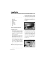
Overhead Video Console
MODEL OHC100
2
© 2002 Directed Electronics, Inc.
Table of Contents
Warranty . . . . . . . . . . . . . . .
Safety Information . . . . . . . .
Important Safeguards . . . . . .
When Cleaning the Vehicle .
While Driving . . . . . . . . . .
When Parked . . . . . . . . . .
Proper Use . . . . . . . . . . .
Temperature . . . . . . . . . .
Repairs . . . . . . . . . . . . . .
Important Information . . . . . .
FCC Notice . . . . . . . . . . . .
Your Warranty . . . . . . . . .
Features . . . . . . . . . . . . . . .
Features . . . . . . . . . . . . .
Accessories . . . . . . . . . . .
Basic Operation . . . . . . . . . .
Monitor Operation . . . . . . .
HP 050 Wireless Headphones
Dome Light Operation . . . .
Installation . . . . . . . . . . . . .
Tools and Materials Needed .
Installation Procedure . . . .
Wiring Guide . . . . . . . . . . . .
© 2002 Directed Electronics, Inc.
.
.
.
.
.
.
.
.
.
.
.
.
.
.
.
.
.
.
.
.
.
.
.
.
.
.
.
.
.
.
.
.
.
.
.
.
.
.
.
.
.
.
.
.
.
.
.
.
.
.
.
.
.
.
.
.
.
.
.
.
.
.
.
.
.
.
.
.
.
.
.
.
.
.
.
.
.
.
.
.
.
.
.
.
.
.
.
.
.
.
.
.
.
.
.
.
.
.
.
.
.
.
.
.
.
.
.
.
.
.
.
.
.
.
.
.
.
.
.
.
.
.
.
.
.
.
.
.
.
.
.
.
.
.
.
.
.
.
.
.
.
.
.
.
.
.
.
.
.
.
.
.
.
.
.
.
.
.
.
.
.
.
.
.
.
.
.
.
.
.
.
.
.
.
.
.
.
.
.
.
.
.
.
.
.
.
.
.
.
.
.
.
.
.
.
.
.
.
.
.
.
.
.
.
.
.
.
.
.
.
.
.
.
.
.
.
.
.
.
.
.
.
.
.
.
.
.
.
.
.
.
.
.
.
.
.
.
.
.
.
.
.
.
.
.
.
.
.
.
.
.
.
.
.
.
.
.
.
.
.
.
.
.
.
.
.
.
.
.
.
.
.
.
.
.
.
.
.
.
.
.
.
.
.
.
.
.
.
.
.
.
.
.
.
.
.
.
.
.
.
.
.
.
.
.
.
.
.
.
.
.
.
.
.
.
.
.
.
.
.
.
.
.
.
.
.
.
.
.
.
.
.
.
.
.
.
.
.
.
.
.
.
.
.
.
.
.
.
.
.
.
.
.
.
.
.
.
.
.
.
.
.
.
.
.
.
.
.
.
.
.
.
.
.
.
.
.
.
.
.
.
.
.
.
.
.
.
.
.
.
.
.
.
.
.
.
.
.
.
.
.
.
.
.
.
.
.
.
.
.
.
.
.
.
.
.
.
.
.
.
.
.
.
.
.
.
.
.
.
.
.
.
.
.
.
.
.
.
.
.
.
.
.
.
.
.
.
.
.
.
.
.
.
.
.
.
.
.
.
.
.
.
.
.
.
.
.
.
.
.
.
.
.
.
.
.
.
.
.
.
.
.
.
.
.
.
.
.
.
.
.
.
.
.
.
.
.
.
.
.
.
.
.
.
.
.
.
.
.
.
.
.
.
.
.
.
.
.
.
.
.
.
.
.
.
.
.
.
.
.
.
.
.
.
.
.
.
.
.
.
.
.
.
.
.
.
.
.
.
.
.
.
.
.
.
.
.
.
.
.
.
.
.
.
.
.
.
.
.
.
.
.
.
.
.
.
.
.
.
.
.
.
.
.
.
.
.
.
.
.
.
.
.
.
.
.
.
.
.
.
.
.
.
.
.
.
.
.
.
.
.
.
.
.
.
.
.
.
.
.
.
.
.
.
.
.
.
.
.
.
.
.
.
.
.
.
.
.
.
.
.
.
.
.
.
.
.
.
.
.
.
.
.
.
.
.
.
.
.
.
.
.
.
.
.
.
.
.
.
.
.
.
.
.
.
.
.
.
.
.
.
.
.
.
.
.
.
.
.
.
.
.
.
.
.
.
.
.
.
.
.
.
.
.
.
.
.
.
.
.
.
.
.
.
.
.
.
.
.
.
.
.
.
.
.
.
.
.
.
.
.
.
.
.
.
.
.
.
.
.
.
.
.
.
.
.
.
.
.
.
.
.
.
.
.
.
.
.
.
.
.
.
.
.
.
.
.
.
.
.
.
.
.
.
.
.
.
.
.
.
.
.
.
.
.
.
.
.
.
.
.
.
.
.
.
.
.
.
.
.
.
.
.
.
.
.
.
.
.
.
.
.
.
.
.
.
.
.
.
.
.
.
.
.
.
.
.
.
.
.
.
.
.
.
.
.
.
.
.
.
.
.
.
.
.
.
.
.
.
.
.
.
.
.
.
.
.
.
.
.
.
.
.
.
.
.
.
.
.
.
.
.
.
.
.
.
.
.
.
.
.
.
.
.
.
.
.
.
.
.
.
.
.
.
.
.
.
.
.
.
.
.
.
.
.
.
.
.
.
.
.
.
.
.
.
.
.
.
.
.
.4
.5
.5
.5
.5
.5
.5
.5
.5
.6
.6
.6
.6
.6
.6
.7
.7
.7
.7
.9
.9
.9
.13
3
Limited Three-Year Warranty
For a period of THREE YEARS from the date of purchase,
troubleshooting or reinstallation of the unit. For service on
Directed Electronics, Inc. ("DIRECTED") promises to the
an out-of-warranty product a flat fate fee by model is
original purchaser to repair or replace, free of cost, with a
charged. Contact your authorized dealer to obtain the serv-
comparable reconditioned model any OVERHEAD CONSOLE
ice charge for your unit.
(hereafter the "UNIT"), which proves to be defective in
workmanship or material defect under normal and reasonable use during the first 3 years after the purchase and
installation of the unit provided the following conditions
are met: the unit was purchased and installed by an authorized DIRECTED dealer; the unit remains in the vehicle in
which the unit was originally installed; and the unit is
returned to DIRECTED.
The unit in question must be
returned to DIRECTED postage paid and must be accompanied by a clear, legible copy of the bill of sale bearing the
following information:
TO THE MAXIMUM EXTENT ALLOWED BY LAW, ALL WARRANTIES, INCLUDING BUT NOT LIMITED TO EXPRESS WARRANTY, IMPLIED WARRANTY, WARRANTY OF MERCHANTABILITY, FITNESS FOR PARTICULAR PURPOSE AND
WARRANTY OF NON-INFRINGEMENT OF INTELLECTUAL
PROPERTY, ARE EXPRESSLY EXCLUDED; AND DIRECTED
NEITHER ASSUMES NOR AUTHORIZES ANY PERSON OR
ENTITY TO ASSUME FOR IT ANY DUTY, OBLIGATION OR
LIABILITY IN CONNECTION WITH ITS PRODUCTS. DIRECTED DISCLAIMS AND HAS ABSOLUTELY NO LIABILITY FOR
ANY AND ALL ACTS OF THIRD PARTIES INCLUDING DEAL-
■
Date of Purchase
ERS OR INSTALLERS. IN THE EVENT OF A CLAIM OR A DIS-
■
Your Full name and address
PUTE INVOLVING DIRECTED OR ITS SUBSIDIARY, THE
■
Authorized dealer's company name and address
■
Type of unit installed
APPLICABLE FEDERAL LAWS SHALL APPLY AND GOVERN
■
Year, make and model of the automobile
THE DISPUTE.
■
Automobile license number
■
Vehicle Identification number
■
Installation receipts
PROPER VENUE SHALL BE SAN DIEGO COUNTY IN THE
STATE OF CALIFORNIA.
CALIFORNIA STATE LAWS AND
THE MAXIMUM RECOVERY UNDER ANY
CLAIM AGAINST DIRECTED SHALL BE STRICTLY LIMITED
TO THE AUTHORIZED DIRECTED DEALER'S PURCHASE
PRICE OF THE UNIT. DIRECTED SHALL NOT BE RESPONSIBLE FOR ANY DAMAGES WHATSOEVER, INCLUDING BUT
All components and accessories other that the unit, includ-
NOT LIMITED TO, ANY CONSEQUENTIAL DAMAGES, INCI-
ing without limitation the remote control, cables and
DENTAL DAMAGES, DAMAGES FOR THE LOSS OF TIME,
installation accessories carry a 60-day warranty from the
LOSS OF EARNINGS, COMMERCIAL LOSS, LOSS OF ECO-
date of purchase of the same.
NOMIC OPPORTUNITY AND THE LIKE. NOTWITHSTANDING
THE ABOVE, THE MANUFACTURER DOES OFFER A LIMITED
This warranty is automatically void if the unit is bought
WARRANTY TO REPLACE OR REPAIR THE CONTROL MOD-
from anyone other than an authorized dealer, the unit's
ULE AS DESCRIBED ABOVE. Some states do not allow lim-
date code or serial number is defaced, missing or altered;
itations on how long an implied warranty will last or the
the unit has been modified or used in a manner contrary to
exclusion or limitation of incidental or consequential dam-
its intended purpose; or the unit has been damaged by
ages. This warranty gives you specific legal rights and you
accident, unreasonable use, neglect, improper service,
may also have other rights that vary from State to State.
installation or other causes not arising out of defects in
DIRECTED does not and has not authorized any person or
workmanship, materials or construction. This warranty is
entity to create for it any other obligation, promise, duty
nontransferable and does not cover batteries. This warran-
or obligation in connection with this UNIT.
ty does not cover labor costs for the removal, diagnosis,
4
© 2002 Directed Electronics, Inc.
Safety Information
WARNING:
TO REDUCE THE RISK OF FIRE OR ELECTRIC SHOCK, DO NOT EXPOSE THIS EQUIPMENT TO
RAIN OR MOISTURE. TO REDUCE THE RISK OF FIRE OR ELECTRIC SHOCK AND ANNOYING
INTERFERENCE, USE ONLY THE INCLUDED HARDWARE.
DIRECTED ELECTRONICS, INC. DISCLAIMS ANY LIABILITY FOR ANY BODILY INJURY,
INCLUDING FATALITIES, OR PROPERTY DAMAGE THAT MAY RESULT FROM ANY IMPROPER OR
UNINTENDED USES OF THIS PRODUCT.
PLEASE READ THIS MANUAL IN ITS ENTIRETY BEFORE BEGINNING THE INSTALLATION.
The OHC100 overhead console is not designed
for viewing by the vehicle operator and should
not be installed where the driver can view it
while driving.
This system is designed and intended for installation by MECP (certified professional)
installers. Tools, equipment and product instal-
lation techniques common to the Mobile
Electronics industry are required, therefore it is
not recommended that the consumer tries to
install this system. Installations or modifications by anyone other than authorized Directed
retailers may limit or void the product warranty.
Please consult with your authorized retailer to
have this system installed.
Important Safeguards
WHEN CLEANING THE VEHICLE
PROPER USE
Do not spray this unit with water or cleaning
solutions. Moisture and the chemicals found in
cleaning fluids could damage the consoles finish
and interior electronics.
Do not touch the screen unless cleaning with a
soft dry cloth. Do not pull or hang from the
monitor mount.
TEMPERATURE
WHILE DRIVING
This unit is intended for use in the rear seat area
only. It should not be installed in a location that
would allow the driver to view it while driving.
LCD monitors are susceptible to extremes in
temperature. If the vehicle interior is extremely
hot or cold the monitor should not be operated
until a comfortable vehicle interior temperature
has been reached.
WHEN PARKED
The screen is easily removable. Always remove or
close the screen when parking for an extended
period of time to avoid potential theft or exposure to direct sunlight.
© 2002 Directed Electronics, Inc.
REPAIRS
If the OHC100 stops working for any reason, discontinue use immediately and consult with your
retailer about any necessary repairs.
5
Important Information
FCC NOTICE
YOUR WARRANTY
This device complies with Part 15 of FCC rules.
Your warranty registration must be completely
Operation is subject to the following two condi-
filled out and returned within 10 days of pur-
tions: (1) This device may not cause harmful
chase. Your product warranty will not be vali-
interference, and (2) this device must accept
dated if your warranty registration is not
any interference received, including interfer-
returned. Make sure you receive the warranty
ence that may cause undesired operation.
registration from your dealer. It is also neces-
Changes
or
modifications
not
expressly
approved by the party responsible for compliance could void the user's authority to operate
sary to keep your proof of purchase, which
reflects that the product was installed by an authorized dealer.
this device.
Features
FEATURES
ACCESSORIES
■
Choice of three monitor sizes.
■
Video Console with IR TX and Dome Light.
■
Monitors can be changed at any time without the need for tools.
■
IR Wireless Headphone x 2.
■
Trim Ring x 1 - Universal.
Built-in Infrared transmitter and two pairs
of wireless headphones.
■
Mini Trim Ring/Adapter x 1.
■
Plastic Mounting Posts x 4.
■
Metal Mounting Plate x 1.
■
Machine Screws x 4.
Removable monitor for added security.
■
Sheet Metal Screws x 4.
■
Built-in dome light for interior lighting.
■
2.6 mm Tape Screws x 11.
■
Adjustable viewing angle.
■
Universal mounting trim ring.
■
Cut-to-length mounting post.
■
■
■
6
On-screen display and wireless remote
control input to allow full control of all
Audio/Video system sources.
NOTE: This manual makes reference to optional Directed
Video parts not included with this product.
© 2002 Directed Electronics, Inc.
Basic Operation
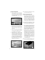
MONITOR OPERATION
■
Pull the bottom of the monitor door
toward the rear of the car and slide the
view angle adjuster all the way to the left,
then release the monitor door. The monitor
should now be at its maximum view angle.
■
Pull on the monitor door until it reaches
the desired view angle and hold it.
■
While still holding the monitor door, slide
the view angle adjuster to the right until
it stops. This will set the monitor door at
the desired view angle.
OPEN/CLOSE THE MONITOR DOOR
■
To Open - Press the monitor door release
button (7); the monitor door will lower
into the viewing position.
■
To Close - Place your hand on the bottom
center of the monitor door (3) and push it
upward into the video console until a click
is heard.
INSTALLING THE MONITOR
■
Open the monitor door to the viewing
position.
■
Hold the monitor with the top tilted away
from the monitor door, and then place the
bottom of the monitor into the two mounting hooks at the bottom of th monitor door.
■
Push the top of the monitor toward the
monitor door until a distinctive click is
heard. the wiring connector at the rear of
the monitor is self guiding and will automatically complete the connection.
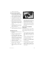
HP050 WIRELESS HEADPHONES
OPERATION
■
The headphones automatically turn on
when placed on your head.
■
Adjust the volume to the desired level
using the volume dial.
■
The headphones must be in line of sight of
the IR lens (10) on the OHC100 to receive
an audio signal.
REMOVING THE MONITOR
BATTERY REPLACEMENT
■
Remove the slide door on the inside of the head-
With the monitor door in the viewing
position, press the monitor release button
(1). At the same time, gently tilt the top of
the monitor away from the monitor door
then lift the monitor up and out of the
mounting hooks.
ADJUSTING THE VIEWING ANGLE
phones to access the batteries. Replace with
standard AAA batteries making sure the batteries are inserted according to the polarity marked
on inside of the headphone case.
DOME LIGHT OPERATION
The viewing angle can be adjusted by sliding the
If the OHC100 has a built-in dome light (8) that
view angle adjuster from side to side.
can be used if the factory dome light must be
■
removed to accommodate the installation. The
Open the monitor door to its current
viewing angle.
© 2002 Directed Electronics, Inc.
built-in dome light has a three-position switch
(9) - OFF, DOOR, and ON.
7
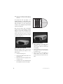
1.
2.
3.
4.
5.
6.
7.
8.
9.
10.
11.
Monitor Release
Monitor Mounting Hook
Monitor Door
Monitor Connector
View Angle Bracket
View Angle Adjuster
Monitor Door Release
Dome Light
Dome Light Switch
IR Receiver
Trim Panel
Monitor Connector
Monitor
Mounts
8
© 2002 Directed Electronics, Inc.
Installation
TOOLS AND MATERIALS NEEDED
■
Screwdriver
■
Power drill with drill bits and screw tip
■
Awl or scribe
■
Razor knife
■
Digital Multi-meter
■
Marker
■
Tape Measure
■
Masking Tape
■
Fabric Cleaner
■
Wire
the amount of cutting required to fit the
trim panel to the contour of the headliner.
5.
After choosing the optimum location, hold
the trim panel up to the headliner to
approximate the final mounting location,
mark the headliner at the center point of
the trim panel from the front to the rear of
the vehicle.
6.
Measure from either side of the vehicle to
the previously marked center point to find
the center point from left to right of the
vehicle and mark it. This will be the point
at which the cutout template will be
positioned for cutting the headliner. Make
sure it is in a location that will allow the
four mounting posts to solidly attach to
the vehicle roof.
INSTALLATION PROCEDURE
MOUNTING LOCATION
1.
Discuss with the vehicle owner a location
in the vehicle that will allow viewing from
the rear passenger seats but not be visible
to the driver. The best location is usually
slightly to the rear of the front seats in the
area of the dome light.
2.
Ensure that the chosen mounting location
will not hinder vehicle operation or the
driver’s view to the rear of the vehicle.
3.
Access the rear of the headliner (remove
the dome light assembly if necessary) to
locate any obstructions. At this time check
for and move any hidden wires, brackets,
hoses or vehicle electronic components
above the headliner that could be damaged during installation.
NOTE: At this time, locate any roof support brackets that
can be used for supporting the mounting bracket.
4.
The headliner area chosen for mounting
should be the flattest possible to reduce
© 2002 Directed Electronics, Inc.
9
CUTTING THE HEADLINER
1.
Insert a pick tool or pin through the
cutout templates center point indicator
and the center point mark on the headliner to align the cutout template with the
center of the vehicle.
NOTE: For extra support it is suggested that the minimum
amount of the headliner be removed.
INSTALL THE MOUNTING PLATE
1.
After removing the headliner cutout, thoroughly clean the inside sheet metal of the
vehicle roof with a degreaser so no dust or
residue remains. This will allow the mounting posts to securely adhere to the vehicle
roof. Extremes in temperature can diminish
the life of some adhesives allowing the
overhead monitor to vibrate or come loose.
NOTE: When installing the mounting plate it is always
advisable to use any available metal roof supports in conjunction with the mounting posts.
10
2.
Sight down the center of the vehicle from
the rear and align the template so it runs
square to the vehicle and other interior
components.
3.
Make sure the arrows point toward the
front of the vehicle. Attach the template
to the headliner using masking tape.
4.
Using both hands for control, cut the
headliner with a razor or sharp knife, being
careful not to slip. DO NOT cut past the heavy
line marked CUT LINE. It is the maximum cut
size when using the trim ring for installation.
The only time the headliner should be cut
past this line is when the monitor mount is
being installed directly to the headliner
without the use of the trim ring.
2.
Place the mounting plate against the vehicle
roof or headliner and mark the location of
the slotted holes that will give the most support. As with the template, make sure the
position of the mounting bracket is square to
the vehicle and interior components.
3.
Using these marks as a guide, remove the
double-stick tape from the mounting posts
and apply to the vehicle roof. Position the
mounting posts at the approximate center
of the slotted holes. This will allow for
maximum adjustability during the final
mounting of the OHC100. After adhering
the mounting posts to the vehicle roof it is
recommended that a generous bead of silicone be applied to their base at the point
of contact with the roof.
NOTE: Take care not to dimple the vehicle exterior or puncture the roof sheet metal when tightening screws.
© 2002 Directed Electronics, Inc.
4.
Install the mounting bracket.
ROUTING THE CABLES AND WIRES
1.
Remove the negative terminal from the battery or remove the fuses for any circuits necessary for this installation before proceeding.
2.
Remove any body panels or brackets necessary for routing the wires and cables.
3.
It is important to run the wires in such a
way that they cannot be damaged or chafe
against sharp metal during reassembly.
4.
5.
All wires should be loomed and properly
fused at the source. Be sure to leave
enough length in the wires and cables to
reach the OHC100 connectors during
mounting.
Extend the dome light wires if necessary to
a length adequate for connecting to the
OHC100's dome light wires.
NOTE: Information about wiring connections can be
found in the Wiring Guide section of this manual.
MOUNTING THE OHC100
1.
Cut the trim ring to match the contour of
the headliner.
2.
Attach the video console to the trim panel
using the 11--2.6 mm tape screws.
3.
Check that the depths of the mounting
posts are adequate by holding the fully
assembled OHC100 up to the roof. It
should be spaced so that the headliner will
not distort when the OHC100 is tightly
screwed to the mounting bracket.
7.
The trim panel should be flush to the
headliner without gaps. If any gaps occur,
adjust the length of the spacers and/or cut
the trim panel to the correct shape.
8.
Install the monitor into the detachable
mounting bracket and fold into the closed
position. Open and close the unit to test
the operation.
VEHICLE-SPECIFIC AFTERMARKET
INSTALLATION
The mini trim ring adapter has a raised adapter
portion designed to adapt the OHC100 to fit
into any aftermarket vehicle-specific overhead
console.
1.
Follow the Installation Procedures (Mounting
Location, Cutting the Headliner, and Routing
Cables and Wires) section outlined in this
guide.
2.
Install the aftermarket vehicle-specific
overhead console following the instructions included with the console.
3.
If depth is an issue, attach the mini trim
ring adapter to the overhead console
(screws not provided).
4.
If adjustment is necessary, the mounting
posts can be cut to length.
5.
Connect all wires and cables. Refer to
Wiring Guide section of this manual.
4.
Connect the cables and wires as described
in the Wiring Guide section of this guide.
6.
Attach the OHC100 assembly to the
mounting bracket using the four machine
screws.
5.
Attach the OHC100 assembly to the
overhead console using the four machine
screws provided.
© 2002 Directed Electronics, Inc.
11
NOTE: Take care not to dimple the vehicle exterior or
puncture the roof sheet metal when tightening
the screws.
The included mini trim ring adapter is for
installing the OHC100 to a flat headliner surface
that needs minimum space. It is also designed to
adapt the OHC100 to fit into vehicle-specific
overhead consoles available through aftermarket
mobile video distributors.
Cut along dotted lines
When using the OHC100 with an aftermarket
overhead console with inadequate mounting
depth, the 1" Mini trim ring adapter can be
modified by cutting out the mounting bracket
portion of the spacer and using it as a universal
1" mini trim ring adapter. this gives the installer
an additional depth of 1".
AFTER THE INSTALLATION
1.
After completion of the video source
installation, reconnect the battery or
replace any fuses that were removed prior
to installation.
2.
Test the operation of the monitor door,
dome lights, and remote control operation
of the video source.
3.
Remove any marks or dirt remaining on
vehicle interior using a quality fabric
cleaner and return the vehicle to the customer.
HEADLINER INSTALLATIONS
Remove the adapter portion of the mini trim
ring where indicated by the dotted line in the
diagram below.
12
1.
Install the mounting posts.
2.
Screw in the supplied metal plate to the
mounting posts.
3.
Attach the 1” mini trim ring adapter to the
overhead console.
4.
The OHC100 can now be installed following
the Installation Procedure of this guide.
© 2002 Directed Electronics, Inc.
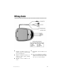
Wiring Guide
■
Accessory - The RED wire should be connected to a fused (+) 12 volt wire that
turns on/off with the key.
■
Ground - The BLACK wire should be connected to a chassis ground, preferably
scrap sheet metal.
■
AV Input - Connect to MCB1000 or AV
source.
© 2002 Directed Electronics, Inc.
■
IR Connector - Connect to MCB1000 or AV
source
NOTE: When using the MCB1000 with the OHC100, to
only use the DIN to DIN cable supplied with the
MCB1000, not the DIN to RCA cable. The DIN to
RCA is only for use without the MCB1000.
13
14
© 2002 Directed Electronics, Inc.
© 2002 Directed Electronics, Inc.
15
The company behind this system is Directed Electronics, Inc.
Since its inception, Directed has had one purpose, to provide consumers with the finest vehicle security, car stereo
products, rear seat entertainment, and accessories available. The recipient of more than 20 patents in the field of
advanced electronic technology, Directed is ISO 9001 registered.
Quality Directed Electronics products are sold and serviced throughout North America and around the world.
Call (800) 274-0200 for more information about our products and services.
Directed® is committed to delivering world-class quality products
and services that excite and delight our customers.
Directed Electronics, Inc.
Vista, CA 92083
www.directed.com
©2002 Directed Electronics, Inc. - All rights reserved
N87101 7-02
16
© 2002 Directed Electronics, Inc.