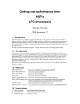
1
AN10736
LPC214x USB simplified - API approach to HID class
Rev. 01 — 12 August 2008
Application note
Document information
Info
Content
Keywords
USB device, LPC214x, HID software library, USB 2.0
Abstract
This document will enable the user to start using the LPC214x USB 2.0
Device peripheral in a matter of hours. It also covers the basics of the
USB 2.0 protocol and explains the API interface for the HID software
library.
AN10736
NXP Semiconductors
LPC214x USB simplified
Revision history
Rev
Date
Description
01
20080812
Initial version.
Contact information
For additional information, please visit: http://www.nxp.com
For sales office addresses, please send an email to: [email protected]
AN10736_1
Application note
© NXP B.V. 2008. All rights reserved.
Rev. 01 — 12 August 2008
2 of 35
AN10736
NXP Semiconductors
LPC214x USB simplified
1. Introduction
The LPC214x family of microcontrollers is comprised of 64-pin ARM 7 based devices that
contain a range of peripherals including a USB 2.0 full-speed device controller. This
device series can be equipped with up to 512 kB of on-chip flash memory and they can
run at a maximum speed of 60 MHz. The patented Memory Accelerator Module (MAM)
together with the 128-bit wide flash makes these chips a great choice for USB-based
applications.
In general, USB programming is a challenge compared to other embedded serial
interfaces since it involves a basic understanding of the USB protocol and the PC/Laptop
interface. With this package we are attempting to simplify the whole USB 2.0
programming experience. This package includes:
1. LPC214x Keil firmware library and associated APIs
2. Delphi host application for HID (Human Interface Device) class. HID is explained in
Section 3 of this manual
3. This manual which explains the basics of the USB protocol and overall library
operation
The LPC214x firmware library is configurable and using the APIs, the user application
will be able to send and receive bytes from the host in a matter of hours. This firmware
library is the modified version of the Keil HID USB example and it provides four basic
APIs to the user application. The APIs hides the complexity of the USB protocol and
successfully transfers all the focus on the application.
This manual attempts to cover all the dots and includes the following sections:
1. Understanding USB (from an application perspective)
2. Software Overview
3. Running the USB application
4. Exercise
2. Understanding USB
USB is a host/peripheral solution. There is only one host and all the peripherals (devices)
are connected to this particular host. Please take note of the single host in this figure.
The host would typically be a PC or a laptop. Connected to the host, would be the
various peripherals via USB hubs.
AN10736_1
Application note
© NXP B.V. 2008. All rights reserved.
Rev. 01 — 12 August 2008
3 of 35
AN10736
NXP Semiconductors
LPC214x USB simplified
HOST/HUB
PC
HUB
Phone
Monitor
HUB
Kbd
Speaker
Pen
Mic
Mouse
Fig 1. USB host example
The LPC214x microcontroller is a great fit for as a peripheral solution since it is equipped
with USB device controller. This IP follows the USB 2.0 specification and supports fullspeed (12Mbps) transfers. The USB 2.0 protocol also supports hi-speed (480Mbps),
however it is not supported in the LPC214x.
This section covers the following:
1. What happens when you plug in the USB cable?
2. USB applications and transfer types
3. Device classes
4. How does data flow between the host and device?
2.1 What happens when you plug in the USB cable?
The starting point of USB communication (in the simplest form) between the host and the
device can be considered to be the plugging of the USB cable into the USB port of the
host.
AN10736_1
Application note
© NXP B.V. 2008. All rights reserved.
Rev. 01 — 12 August 2008
4 of 35
AN10736
NXP Semiconductors
LPC214x USB simplified
Fig 2. Host hub port
The host hub port (Fig 2) is able to detect the attachment of the USB device and makes
the host controller aware of the same. The host controller then starts communicating with
the USB device (which could be a mouse, keyboard, flash drive etc.). This initial
communication between the host and the device is termed as “bus enumeration”. Bus
enumeration is the process through which the host learns about the capabilities of the
device. Since any USB device can be connected to the host hub port at anytime, bus
enumeration becomes the essential first step of USB communication.
Bus enumeration includes the following key steps:
1. Assigning an address to the device: All devices on the USB bus will be given a
unique address from the host. However when any device starts communicating with
the host, it always start communicating using address 0.
2. Reading data structures from the device: As we know, any peripheral can be
connected to the USB Host hub port. Hence, each time a peripheral is connected,
the host will request a series of data structures from the device that will inform the
host about its capabilities. These data structures are called “descriptors”. Descriptors
will contain a range of information including details about the Vendor and the product
(Vendor and Product IDs will be covered in Section 4).
3. Assigning and loading a device driver: Using the information from the descriptors, the
host controller is now able find the device driver that can manage communication
with the device.
4. Selecting a configuration: Once the device driver is loaded, it will request a
configuration from the device. A device may have different configurations. For
example, a high power device may also support a low power mode, resulting in a
configuration descriptor for each mode. Most devices typically support only one
configuration.
Bus enumeration is transparent to the user. After the USB cable is plugged in, the host
enumerates the device. Once enumeration is complete, Windows adds the new device to
the Device Manager display in the Control Panel. The device is then configured and
AN10736_1
Application note
© NXP B.V. 2008. All rights reserved.
Rev. 01 — 12 August 2008
5 of 35
AN10736
NXP Semiconductors
LPC214x USB simplified
ready to transfer data. We will revisit bus enumeration when we run the actual example
that is provided in this package.
2.2 USB applications and transfer types
Let’s look at some of the most common USB applications and try to understand the
different types of USB transfers.
2.2.1 Interrupt transfer
Fig 3. Keyboard and mouse
Interrupt transfers are useful when data has to transfer within a specific amount of time.
Typical applications would include keyboard and mouse (Fig 3). Users don’t want a
noticeable delay between pressing a key or moving a mouse and seeing the result on the
screen. Though the name “interrupt transfer” suggests the device can cause a hardware
interrupt to the PC, the truth is like all other USB transfers, an interrupt transfer only
happens when the host polls the device. The transfer is interrupt-like because there is a
guarantee that the host will request or send data within a specified time interval (i.e.
polling interval).
Interrupt transfers are also popular because Windows includes class drivers that enable
applications to do interrupt transfers that conform to the HID specification (HID is
explained later in section).
2.2.2 Bulk transfer
Fig 4. Printer, scanner, and CD-ROM
AN10736_1
Application note
© NXP B.V. 2008. All rights reserved.
Rev. 01 — 12 August 2008
6 of 35
AN10736
NXP Semiconductors
LPC214x USB simplified
When a file is sent for printing one typically does not care much of the speed at which the
file reaches the printer. However, it is very important that the file reaches the printer
without any errors. Bulk transfers are useful for transferring data where time is not
critical. Typical applications would be printers, scanners and CD-ROMs (Fig 4). A bulk
transfer can send large amounts of data without creating congestion on the bus because
other transfer types occur before bulk transfers. On an otherwise idle bus, bulk transfers
are the fastest transfer type. Bulk transfers detect errors and use data-toggle bits to
ensure that no data is lost.
2.2.3 Isochronous transfer
Fig 5. USB speakers
Isochronous transfers are streaming, real-time transfers that are useful when data has to
arrive at a constant rate, or by a specific time and occasional errors can be tolerated.
USB speakers (Fig 5) would be an example of a product that uses isochronous transfers.
Such devices need a guaranteed delivery rate for data but error correction is not a must.
The human ear would not be able to pick up small errors in audio samples every now
and then. Under normal circumstances, a USB transfer should experience no more than
a very occasional error due to line noise.
2.2.4 Control transfer
All the above USB devices have to first go through the “bus enumeration” process. As
mentioned above, bus enumeration is the process wherein the host gets to know about
the capabilities of the device.
A control transfer type follows a strict format for communication and all devices must
support this transfer. So, if one follows a typical USB communication trace acquired from
a USB protocol analyzer they would notice that all the initial communication is handled by
control transfers and then depending upon the application, the transfer type will switch to
either Interrupt, Bulk, or Isochronous. As an example, a printer would use control transfer
during the bus enumeration process and then switch to bulk transfers for transferring files
and status information.
2.3 Device classes
USB devices that share many attributes or request similar services are grouped within
the same class specification. A class specification defines functions that describe how
the data will be transferred. They also define the number and type of buffers that are
supported by the class. Classes make it easier to develop device drivers and firmware in
a standardized way. Windows and other operating systems include drivers for common
classes. If the device’s class is supported by the operating system, a driver for the device
need not be provided (for instance this applies to the HID class).
AN10736_1
Application note
© NXP B.V. 2008. All rights reserved.
Rev. 01 — 12 August 2008
7 of 35
AN10736
NXP Semiconductors
LPC214x USB simplified
Let’s look at some of the most common classes:
1. Human Interface Device (HID):
2. Mass storage:
3. Printer:
4. Audio device:
5. Imaging:
2.4 How does data flow between the host and device?
Data flows “IN” and “OUT” with respect to the host. If data is going from the device to
the host, it is called an “IN transaction” and if the data is going from the host to the
device, it is called an “OUT transaction” (as shown below). A typical transfer (control,
isochronous, bulk, interrupt) is made of several transactions. A transaction is in turn
made of up several packets.
Fig 6 is a general picture that shows IN and OUT transactions with respect to the host.
AN10736_1
Application note
© NXP B.V. 2008. All rights reserved.
Rev. 01 — 12 August 2008
8 of 35
AN10736
NXP Semiconductors
LPC214x USB simplified
Fig 6. In/out host transactions
On the device side, data that needs to be sent to the host and data that is received from
the host gets collected in an area called “Endpoint”. An endpoint is a buffer that can
store multiple bytes. The host also has buffers at its end but they are not called
endpoints. So, for any device, it would have both IN and OUT endpoints (All devices
must have an IN endpoint 0 and OUT endpoint 0 since this is used by control transfer for
bus enumeration).
Let’s modify Fig 6 and show more details using endpoints.
AN10736_1
Application note
© NXP B.V. 2008. All rights reserved.
Rev. 01 — 12 August 2008
9 of 35
AN10736
NXP Semiconductors
LPC214x USB simplified
Fig 7. In/out host transactions with endpoints
3. USB software overview
In this package, we have selected to use the HID class specification. By using the HID
class, we are saving ourselves the trouble of creating a custom device driver (on the host
side). Also, there is a lot of support from the online community in terms of host
applications.
For the LPC214x (now a HID device) to work correctly with our laptops (USB Host), the
following software packages would be needed:
1. USB Device (in this case LPC214x)
• Device Firmware- In the below figure, this would constitute “HID USB Library” and
“User Application”
2. USB Host (typically PC/laptop)
• Windows HID driver
• Host Delphi Application
AN10736_1
Application note
© NXP B.V. 2008. All rights reserved.
Rev. 01 — 12 August 2008
10 of 35
AN10736
NXP Semiconductors
LPC214x USB simplified
Fig 8. USB host/device software example
3.1 LPC214x device firmware
Fig 9. Device example
In this package we are attempting to provide the HID software as a library to the user
application. As mentioned before, the Keil HID Software is adopted. The HID class
details are now configurable using the modified configuration wizard that is provided in
AN10736_1
Application note
© NXP B.V. 2008. All rights reserved.
Rev. 01 — 12 August 2008
11 of 35
AN10736
NXP Semiconductors
LPC214x USB simplified
this package. Once configured, the package should be imported to the user application
as a library and then it can be accessed using a very simple API interface.
With this approach, the user application need not understand the entire details of the
USB protocol and focus all the attention on the application. The APIs are explained in
detail in the following section.
3.2 USB host details
Fig 10. Host example
On the host side, we don’t have to provide any device drivers for the HID Class.
Windows OS comes pre-built with the HID class driver and it provides an API interface
that could be used by PC-based applications to create a host application. In this case, we
have chosen Delphi to create the host application.
4. Running the USB application
This section covers the following:
1. Software/setup explained
2. Configuring the library
3. The HID API interface
4. Building the HID library and user application
5. Running the applications
4.1 Software/setup explained
This package comprises of the following packages:
AN10736_1
Application note
© NXP B.V. 2008. All rights reserved.
Rev. 01 — 12 August 2008
12 of 35
AN10736
NXP Semiconductors
LPC214x USB simplified
Fig 11. Software packages
4.1.1 User application – Blinky
The Blinky project is a typical first choice for running the first example on an evaluation
board. This also would be our choice for a user application. After running this example,
one can hopefully realize how the API interfaces make it easy for the host and device to
communicate. The target of this project is the internal Flash of the LPC2148. This demo
is all set to run with the Delphi Host Application and the Keil MCB 2140 board. The HID
Library file is configured accordingly.
4.1.2 HID library – LPC2148 firmware
This library is a modified version of the Keil HID example that was originally developed
for the LPC2148. The original Keil example can be obtained from the below website:
http://www.nxp.com/redirect/keil.com/306.asp
The modifications though subtle helped us to create a simple library that simplifies the
HID experience. Once the library is created, users have to just use four API calls to
access it.
4.1.3 Host application – Delphi
A Delphi HID application is provided with complete project files and source code. The
user application i.e. Blinky is configured to run with the Delphi application. Fig 12 shows
a screenshot of the Delphi Application.
AN10736_1
Application note
© NXP B.V. 2008. All rights reserved.
Rev. 01 — 12 August 2008
13 of 35
AN10736
NXP Semiconductors
LPC214x USB simplified
Fig 12. Screenshot of Delphi application
4.1.4 Setup
Fig 13. Setup example
Configure the setup as shown in Fig 13 using the Keil MCB 2140 board and the Keil
ULINK. Please browse to the LPC2148 Firmware folder and open the HID.uv2 project.
AN10736_1
Application note
© NXP B.V. 2008. All rights reserved.
Rev. 01 — 12 August 2008
14 of 35
AN10736
NXP Semiconductors
LPC214x USB simplified
Fig 14. Firmware folder screenshot
Now, open the configuration wizard by clicking on 1 and 2 below:
1- usbcfg.h
2- Configuration wizard
Fig 15. Configuration wizard screenshot
4.2 Configuring the library
4.2.1 Vendor ID and Product ID
The configuration wizard provides a GUI for configuring the Vendor and the Product
information in the form of Vendor and Product IDs. Each vendor (like NXP
Semiconductors) will have his own unique Vendor ID. A Vendor ID can be obtained from
the following website: http://www.nxp.com/redirect/usb.org/developers/vendor/. Also each
vendor can have several Product IDs.
Why is it important to know about Vendor and Product IDs? Later on, we will be invoking
a host application that will be able to communicate with the LPC2148. This host
AN10736_1
Application note
© NXP B.V. 2008. All rights reserved.
Rev. 01 — 12 August 2008
15 of 35
AN10736
NXP Semiconductors
LPC214x USB simplified
application should have the same matching IDs for it to recognize the LPC2148. We will
revisit this in Section 4.
Fig 16. Vendor/product ID screenshot
4.2.2 HID report
In the HID class, data is exchanged between the host and the device in structures called
reports. During bus enumeration, the device will inform the host the format of the report.
In this case, the report structure is a simple array and the size is configurable. In the
configuration wizard, the size of IN and OUT reports are set by “Report Bytes In” and
“Report Bytes Out” respectively (as shown in the figure below).
Under the HID class support wizard it can be seen that the HID package is configured to
send and receive 1 byte through two arrays, InReport [ ] and OutReport [ ] respectively.
These arrays are declared as global structures in the library and hence will be available
to the user application. Also, the polling interval from the host for both IN and OUT
transactions is set at 8ms. Here polling interval means that the host will request a report
from the device every 8ms (using an IN transaction) and it will send a report to the device
every 8ms (using an OUT transaction).
At this time, we are just planning to enumerate the LPC2148 as a “generic HID device”.
As a generic HID device, the LPC2148 will be able to manage simple communication
between the host and device.
4.3 The HID API interface
The HID library provides four basic APIs that would illustrate the functioning of the HID
class. These APIs (without parameters) are shown in the below image:
AN10736_1
Application note
© NXP B.V. 2008. All rights reserved.
Rev. 01 — 12 August 2008
16 of 35
AN10736
NXP Semiconductors
LPC214x USB simplified
Fig 17. HID library APIs
4.3.1 USB_Init (address of GetInReport(), address of SetOutReport())
This function handles the initialization of the USB interface in the LPC2148 which
includes resetting the USB interface and setting the address to 0. As mentioned in
Section 2.1, during bus enumeration, the LPC2148 would communicate with the host
using Address 0 on Endpoint 0.
This function takes the addresses of the two other APIs as parametersGetInReport(void) and SetOutReport(void). These two APIs are defined by the user
application. The HID library will be calling these functions at run time. Hence dynamic
binding had to be incorporated that enables the HID library to call these functions at
runtime using function pointers.
4.3.2 USB_Connect (Boolean)
This function initiates the connect sequence if the Boolean value is set to TRUE and
initiates the disconnect sequence if the Boolean value is set to FALSE. To be more
precise, it uses the SoftConnect feature of the LPC214x. To get more information on
SoftConnect please refer the LPC214x User Manual.
If the SoftConnect™ feature is not being used, it is not necessary to call the
USB_Connect() function.
4.3.3 GetInReport(void) and SetOutReport(void)
These two functions have to be defined by the user.
Let’s revisit Section 2.4 and analyze some key points:
AN10736_1
Application note
© NXP B.V. 2008. All rights reserved.
Rev. 01 — 12 August 2008
17 of 35
AN10736
NXP Semiconductors
LPC214x USB simplified
Fig 18. In/out host transactions with endpoints
1. The host and the device send and receive data using IN and OUT transactions and
they use their respective IN and OUT buffers.
2. Within the HID class data gets transferred between the host and the device using
reports. Reports can have a flexible format (in this case they are simple arrays). The
size of these arrays are set by the USB configuration wizard (Section 4.2.1)
3. The host will poll the device at regular intervals and request/send reports
So the above figure can be further expanded to the following:
Fig 19. Data accumulation in OutReport
As shown above, data sent from the host will get accumulated in OutReport[ ]. Similarly,
data that needs to be sent to the host needs to get accumulated in InReport. When host
requests the data, the HID library will empty the InReport[] into the respective IN buffer
(endpoint).
GetInReport() will be called by the HID Library when host requests a report from the
device. User has to define GetInReport() and fill the InReport [ ] accordingly.
SetOutReport () will be called by the HID library when host has sent a report for the
device. User has to define SetOutReport() and empty the OutReport [ ] accordingly.
AN10736_1
Application note
© NXP B.V. 2008. All rights reserved.
Rev. 01 — 12 August 2008
18 of 35
AN10736
NXP Semiconductors
LPC214x USB simplified
NOTE:
The size of InReport[ ] and OutReport[ ] is set in the usb_api.h file and this should match
the size set in the configuration wizard (Section 4.2.1). The usb_api.h file is located in the
Blinky folder.
1
2
#define USB_HID_REPORT_IN 1
#define USB_HID_REPORT_OUT 1
For example, if the report Bytes In and Report Bytes Out are set to 2 then the above
definitions should also be set to 2.
4.4 Building the HID library and user (blinky) application
So far we have understood the HID library configuration wizard and we have also
understood the HID API interface. Let’s go ahead and build the HID Library.
4.4.1 Building the HID library
To build a library in the Keil environment carry out the following steps:
4.4.1.1 Step 1: Change project settings to create a library output
AN10736_1
Application note
© NXP B.V. 2008. All rights reserved.
Rev. 01 — 12 August 2008
19 of 35
AN10736
NXP Semiconductors
LPC214x USB simplified
Fig 20. Step 1 screenshot
4.4.1.2 Step 2: Build the library
Let’s go ahead and build the library
Fig 21. Step 2 screenshot
The HID.lib file gets created in the Obj folder. A copy of this file already exists in the
Blinky folder. If any changes are made to the library then the new HID.lib file should be
copied to the Blinky folder.
4.4.2 Building the user application - Blinky
The Blinky example is all set to build. However, if the user wishes to add the library to
this application then a simple step needs to be carried out. In the project workspace,
simply create a new group called “Library” (show on left below). Right-click on the
“Library” folder and click on “Add files to Group Library”. Under files of type, select *.lib
files and then select HID.lib.
AN10736_1
Application note
© NXP B.V. 2008. All rights reserved.
Rev. 01 — 12 August 2008
20 of 35
AN10736
NXP Semiconductors
LPC214x USB simplified
Fig 22. Blinky screenshot
Let’s build the user application together with the HID library. Click on the build button(as
shown below). Once the application is built successfully, load the code into the LPC2148
Flash by using the “Load” button as shown below:
Fig 23. Build screenshot
The LPC2148 is now ready to communicate with the Delphi host application
4.5 Running the LPC2148 with the Delphi application
Let’s run the application and at the same time try to relate this to our understanding of
the USB protocol.
4.5.1 Bus enumeration
Let’s see bus enumeration in action. Please carry out the following steps:
1. Disconnect the ULINK from the LPC2148 evaluation board.
2. On the host side, right click on the “My Computer’ and browse to System Properties
(window 1). Then click on “Device Manager” (window 2 will show up).
3. Keeping this window open, connect the LPC2148 over USB to the host (PC/Laptop).
As the LPC2148 undergoes “bus enumeration” the window will get updated.
4. Once enumeration is completed, the “USB Human Interface Device” icon should
show up on Window 2 (shown in red box below). Double-clicking on “USB Human
Interface Device” should lead to window 3.
5. This window identifies the USB HID device as a Keil MCB2140 HID. This shows that
the device has enumerated correctly and is now ready for use.
AN10736_1
Application note
© NXP B.V. 2008. All rights reserved.
Rev. 01 — 12 August 2008
21 of 35
AN10736
NXP Semiconductors
LPC214x USB simplified
(The below images were captured on Windows XP Professional Version 2002)
Fig 24. Bus enumeration screenshots
4.5.1.1 IN and OUT flow of data
To see communication between the host and the LPC2148, let’s open the Delphi Host
Application. Please open LPC214x_HID.exe under the Delphi folder. This application has
the same Vendor ID and Product ID as set in the HID Library/firmware (Section 4.2.1). If
these values are changed, the host application will not be able to identify the LPC2148.
If the above IDs are matched, the LPC2148 board will get detected by the Delphi
application and this will be indicated by the color of the bottom bar (turning green).
AN10736_1
Application note
© NXP B.V. 2008. All rights reserved.
Rev. 01 — 12 August 2008
22 of 35
AN10736
NXP Semiconductors
LPC214x USB simplified
Fig 25. Delphi host application screenshot
At this point, bus enumeration is completed and the host is already polling the device for
data. This further means that there has been a change in transfer type. During bus
enumeration the device and the host communicate using Control transfers and then
depending upon the application, the transfer type will shift to Interrupt, Isochronous or
Bulk. In this case, the LPC2148 is enumerating as a generic HID device. So the transfer
type will switch to Interrupt transfer. One can find out the exact switch of the transfer type
by analyzing the communication over a USB protocol analyzer.
Fig 26. Host timeline
AN10736_1
Application note
© NXP B.V. 2008. All rights reserved.
Rev. 01 — 12 August 2008
23 of 35
AN10736
NXP Semiconductors
LPC214x USB simplified
As shown in Fig 26, the red arrow indicates a timeline. The host at some point in time will
switch from Control to Interrupt. Now the host will continuously poll the device for reports
and send a report to the device when the user updates the application.
4.5.2 Host application functions
1. One can get more information on the device by clicking on the top buttons from
Vendor Name all the way down to Interface. When these buttons are clicked the
Delphi application will get this information from descriptors that were exchanged
during the enumeration process. As mentioned earlier, descriptors are structures that
provide information on the capabilities of the device (Section 2.1).
Action (Descriptors) - Click on all the buttons and the GUI should get updated with the
information from the descriptors.
Fig 27. GUI screenshot
2. The host is continuously polling the LPC2148 for an IN report every 8ms (as set by
the configuration wizard). This further means that the HID lib will call
GetInReport(void) every 8 ms and enquire the user application if there is any data for
the host (GetInReport(void) is defined in the Blinky project)
Lets analyze the current GetInReport(void) function:
1
2
3
4
5
6
7
8
9
void GetInReport (void)
{
if ((IOPIN0 & PBINT) == 0)
{ /* Check if PBINT is pressed */
InReport[0] = 0x01;
} else {
InReport[0] = 0x00;
}
}
AN10736_1
Application note
© NXP B.V. 2008. All rights reserved.
Rev. 01 — 12 August 2008
24 of 35
AN10736
NXP Semiconductors
LPC214x USB simplified
InReport[] gets a 0 or a 1 depending upon the status of the INT1 button. When
this data arrives on the host side it is indicated to the Delphi application. The
application then goes and reads the data and changes the INT1 GUI element
status accordingly.
Action (“IN” Flow of Data) - Click on the INT1 button on the MCB2140 board and GUI
should get updated with the INT1 status.
Fig 28. INT1 status screenshot
3. Check boxes from P1.16 to P1.23 correspond to the LEDs on the board. By checking
these boxes, one can set or clear the LED status on the MCB board. Similar to IN
reports checking the boxes will generate an OUT report to the device. The HID
library will then call SetOutReport() in the user application that will enable or disable
the LEDs on the board.
Lets analyze the current SetOutReport(void) function:
1
2
3
4
void SetOutReport (void)
{
IOPIN1 = (IOPIN1 & ~LEDMSK) | (OutReport[0] << 16);
}
As shown above, the value of OutReport[] gets sent to IOPIN1 which updates
the LEDs accordingly.
Action (“OUT” Flow of Data) - Click on the check boxes on the Delphi application and
as the boxes are clicked the corresponding LEDs on the board should light up.
AN10736_1
Application note
© NXP B.V. 2008. All rights reserved.
Rev. 01 — 12 August 2008
25 of 35
AN10736
NXP Semiconductors
LPC214x USB simplified
Fig 29. Board detection screenshot
5. Exercise
In this section, we will run some short exercises and attempt to understand the USB
interface on both the device and host side.
5.1 Changing the vendor and product ID
Let’s try to understand the significance of Vendor and Product IDs. Please double-click
on their values and change it any other hex value.
Fig 30. Changing vendor and product ID screenshot
AN10736_1
Application note
© NXP B.V. 2008. All rights reserved.
Rev. 01 — 12 August 2008
26 of 35
AN10736
NXP Semiconductors
LPC214x USB simplified
After making the above modification to the HID.uv2 project, carry out the following steps:
1. Re-connect the ULINK to the MCB2148 board
2. Build the HID library
3. Copy the new HID.lib file to the Blinky project folder
4. Build the Blinky project and load the user application into the LPC2148
5. Go through the bus enumeration process
Now, open the Delphi application. The application will not be able to recognize the
LPC2148 because the vendor and product ids don’t match.
Fig 31. Delphi application screenshot
Note: For a host application to recognize the device firmware, they should have
the same Vendor and Product IDs.
5.2 Descriptors
Let’s try to understand some aspects of descriptors. Below, we were able to enquire
some information from the device.
AN10736_1
Application note
© NXP B.V. 2008. All rights reserved.
Rev. 01 — 12 August 2008
27 of 35
AN10736
NXP Semiconductors
LPC214x USB simplified
Fig 32. Descriptor information screenshot
Let’s open the descriptor file within the HID. Uv2 project.
Fig 33. Descriptor file screenshot
In usbdesc.c there are several descriptors including:
1. HID report descriptor
2. USB standard device descriptor
3. USB configuration descriptor
4. USB String descriptor
Reading the comments associated with each line of code will give the idea some idea on
what the descriptor will achieve. For instance, the Vendor and Product IDs are listed in
the device descriptor. The report structure and size gets listed in the report descriptor. At
this time let’s focus our interest on the String Descriptor. The strings present in this
structure should match the strings on the Delphi application.
AN10736_1
Application note
© NXP B.V. 2008. All rights reserved.
Rev. 01 — 12 August 2008
28 of 35
AN10736
NXP Semiconductors
LPC214x USB simplified
Fig 34. Descriptor information screenshot
Let’s modify the “Serial Number” value from “DEMO” to “2148”.
Just with these changes, build the library. Update the library file in the Blinky project and
build the Blinky application as well. Download the code into the LPC2148 and let it
enumerate. If the Delphi application is open then wait for the bottom bar to become
green. Once the device is detected, click on the buttons again and you will get the
information from the updated descriptors (as shown below):
AN10736_1
Application note
© NXP B.V. 2008. All rights reserved.
Rev. 01 — 12 August 2008
29 of 35
AN10736
NXP Semiconductors
LPC214x USB simplified
Fig 35. Updated descriptor screenshot
5.3 Host applications - Delphi
5.3.1 Software
This document would not be complete without discussing a few points regarding the
Delphi application. An evaluation version of the Delphi 2007 for Win32 software can be
downloaded from the following website:
http://www.nxp.com/redirect/codegear.com/win32
The Delphi application comes with complete source code and project files. Along with
this package we also used a HID component that acts like a bridge between the
application and the HID device driver. This HID component can be downloaded for free
from the following website:
http://www.nxp.com/redirect/soft-gems.net/
This component gives complete access to the LPC2148 generic HID device.
AN10736_1
Application note
© NXP B.V. 2008. All rights reserved.
Rev. 01 — 12 August 2008
30 of 35
AN10736
NXP Semiconductors
LPC214x USB simplified
Fig 36. HID component
5.4 Code snippets
Out Report:
Because of the HID component, sending an OUT report to the device becomes as simple
as the below code snippet:
As seen above, the OUT report gets initialized and then is sent downstream using a
simple API: LPC2140_HID.Writefile ()
Enumeration:
The HID component offers several “events” that can be used by the Delphi application. In
this application, the following events are utilized: the enumerate event, the Device Data
(IN report) event and Device Change. The enumerate and device data events are
discussed below.
AN10736_1
Application note
© NXP B.V. 2008. All rights reserved.
Rev. 01 — 12 August 2008
31 of 35
AN10736
NXP Semiconductors
LPC214x USB simplified
Fig 37. Enumeration events screenshot
The enumerate event is triggered when Windows is enumerating the LPC2148. On the
application front, the following function will be called. As seen below, the very first step
after this event is to match the Vendor and Product ID’s with that of the application.
IN report:
The device data event occurs when the USB device has sent some data to the USB host.
This further means the HID component will trigger this event when a report is received
from the LPC2148. On The application front, the following function gets called:
AN10736_1
Application note
© NXP B.V. 2008. All rights reserved.
Rev. 01 — 12 August 2008
32 of 35
AN10736
NXP Semiconductors
LPC214x USB simplified
SetOutReport() sends a 0 or 1 depending upon the status of the INT1 button. On the host
side, if the data is 1 then the text color changes to red else the text color remains cream.
6. References
Hopefully, after reading the above chapters the reader has gained some insight into the
USB interface and its protocol. An essential next step would be to read some related
documents on the USB protocol and the USB chapter of the LPC214x user manual.
• USB 2.0 Specification
http://www.nxp.com/redirect/usb.org/developers/docs/
• The USB Complete book
http://www.nxp.com/redirect/lvr.com/usbc.htm
• Universal Serial Bus System Architecture
• LPC214x UM and other related information
http://www.standardics.nxp.com/products/lpc2000/lpc214x/
• Host applications for HID
http://www.nxp.com/redirect/lvr.com/hidpage.htm
AN10736_1
Application note
© NXP B.V. 2008. All rights reserved.
Rev. 01 — 12 August 2008
33 of 35
AN10736
NXP Semiconductors
LPC214x USB simplified
7. Legal information
7.1 Definitions
Draft — The document is a draft version only. The content is still under
internal review and subject to formal approval, which may result in
modifications or additions. NXP Semiconductors does not give any
representations or warranties as to the accuracy or completeness of
information included herein and shall have no liability for the consequences
of use of such information.
7.2 Disclaimers
General — Information in this document is believed to be accurate and
reliable. However, NXP Semiconductors does not give any representations
or warranties, expressed or implied, as to the accuracy or completeness of
such information and shall have no liability for the consequences of use of
such information.
Right to make changes — NXP Semiconductors reserves the right to make
changes to information published in this document, including without
limitation specifications and product descriptions, at any time and without
notice. This document supersedes and replaces all information supplied prior
to the publication hereof.
Suitability for use — NXP Semiconductors products are not designed,
authorized or warranted to be suitable for use in medical, military, aircraft,
space or life support equipment, nor in applications where failure or
malfunction of a NXP Semiconductors product can reasonably be expected
to result in personal injury, death or severe property or environmental
damage. NXP Semiconductors accepts no liability for inclusion and/or use of
NXP Semiconductors products in such equipment or applications and
therefore such inclusion and/or use is for the customer’s own risk.
Applications — Applications that are described herein for any of these
products are for illustrative purposes only. NXP Semiconductors makes no
representation or warranty that such applications will be suitable for the
specified use without further testing or modification.
7.3 Trademarks
Notice: All referenced brands, product names, service names and
trademarks are property of their respective owners.
AN10736_1
Application note
© NXP B.V. 2008. All rights reserved.
Rev. 01 — 12 August 2008
34 of 35
AN10736
NXP Semiconductors
LPC214x USB simplified
8. Contents
1.
2.
2.1
2.2
2.2.1
2.2.2
2.2.3
2.2.4
2.3
2.4
Introduction .........................................................3
Understanding USB ............................................3
What happens when you plug in the USB cable?..4
USB applications and transfer types .....................6
Interrupt transfer....................................................6
Bulk transfer ..........................................................6
Isochronous transfer..............................................7
Control transfer......................................................7
Device classes ......................................................7
How does data flow between the host and device?
...........................................................................8
3.
USB software overview.....................................10
3.1
LPC214x device firmware ...................................11
3.2
USB host details..................................................12
4.
Running the USB application ...........................12
4.1
Software/setup explained ....................................12
4.1.1
User application – Blinky .....................................13
4.1.2
HID library – LPC2148 firmware..........................13
4.1.3
Host application – Delphi.....................................13
4.1.4
Setup...................................................................14
4.2
Configuring the library .........................................15
4.2.1
Vendor ID and Product ID ...................................15
4.2.2
HID report............................................................16
4.3
The HID API interface .........................................16
4.3.1
USB_Init (address of GetInReport(), address of
SetOutReport())................................................17
4.3.2
USB_Connect (Boolean) .....................................17
4.3.3
GetInReport(void) and SetOutReport(void) .........17
4.4
Building the HID library and user (blinky)
application ........................................................19
4.4.1
Building the HID library........................................19
4.4.1.1
Step 1: Change project settings to create a
library output ....................................................19
4.4.1.2
Step 2: Build the library ....................................20
4.4.2
Building the user application - Blinky...................20
4.5
Running the LPC2148 with the Delphi application
.........................................................................21
4.5.1
Bus enumeration .................................................21
4.5.1.1
IN and OUT flow of data...................................22
4.5.2
Host application functions ...................................24
5.
Exercise .............................................................26
5.1
Changing the vendor and product ID...................26
5.2
Descriptors ..........................................................27
5.3
Host applications - Delphi....................................30
5.3.1
Software ..............................................................30
5.4
Code snippets .....................................................31
6.
7.
7.1
7.2
7.3
8.
References .........................................................33
Legal information ..............................................34
Definitions............................................................34
Disclaimers ..........................................................34
Trademarks .........................................................34
Contents .............................................................35
Please be aware that important notices concerning this document and the product(s)
described herein, have been included in the section 'Legal information'.
© NXP B.V. 2008. All rights reserved.
For more information, please visit: http://www.nxp.com
For sales office addresses, email to: [email protected]
Date of release: 12 August 2008
Document identifier: AN10736_1