1
User manual for the KAPtery SkyShield autoKAP controller
PCB circuit and Arduino sketch at KAPtery.com/guides
Technical support: http://kaptery.com/contact/
SkyShield Github page
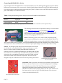
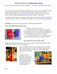
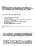
The SkyShield is an open-source custom circuit board
which is a "shield" for an Arduino Nano. The Nano is a
tiny microcontroller that can be easily programmed to
respond to inputs and send signals to connected devices.
When coupled with a Nano, the shield allows easy
connection of cameras, servos, and a battery pack using
RC connectors. A sketch (program) loaded on the Nano
can define eight different regimes of pan/tilt/shoot
sequences, and any regime can be selected in the field
using a DIP switch on the shield. The SkyShield is a through-hole circuit board so anyone can solder one together
from an inexpensive kit of components. The Saturn V Rig is designed to be operated by a SkyShield controller for
capturing multiple adjacent photos for panoramas.
Many applications: Although the primary intended use of the SkyShield is to take aerial photos that can be stitched
together into panoramas, it can also do other things. A mode which takes only nadir and near-nadir photos could
be created for capturing photo sets to be used for structure-from-motion 3D modeling. A simple mode could
instruct two (or more) cameras on a special camera rig to shoot simultaneously, for example for visible and near
infrared photo pairs for vegetation analysis. A CHDK script running on the PowerShot could respond to signals
from the SkyShield to zoom the lens, bracket each shot, or switch to video. For non-aerial photography, a tripod
mounted rig could capture many telephoto photos for stitching into gigapixel panoramas (like a Gigapan imager).
The SkyShield allows two cameras (or other devices) and four servos (or other devices) to be connected. This
makes it easy to exploit the power of an Arduino for a range of purposes including environmental sensing and
robotics. It is easy to load your custom Arduino sketch onto the Nano.
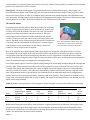
Arduino Nano
The SkyShield plugs in to an Arduino Nano which is one of the smaller
standard Arduino packages. The Nano compatible board that is part of
SkyShield packages is the 3.0 version based on the ATmega328 chip. It
has more or less the same functionality of the Arduino Duemilanove,
but it is very small and inexpensive. It has a small USB mini-B
A Nano with the SkyShield plugged in to
connector. The Nano has 14 digital pins, and four of these are routed
the bottom.
to servo headers on the SkyShield. For different applications an
Arduino sketch can designate pins as either analog or digital and as either input or output. The ATmega328 has 32
KB of flash memory for storing code, 2 KB of SRAM, and 1 KB of EEPROM. The clock speed is 16 MHz.
Connecting the SkyShield to the Nano
The SkyShield should be attached to an
Arduino Nano as shown with the DIP switch
at the same end as the USB port on the Nano.
Page | 1
Connecting the SkyShield to devices
A typical application of the SkyShield is to control pan and tilt servos on a KAP rig and trigger the camera’s shutter
between servo movements. Four servos can be controlled with Arduino digital pins (all provide PWM output) and
two cameras can be controlled with Arduino analog pins (Table 1). Camera control via CHDK requires a simple 5V
pulse to the USB port of a Canon PowerShot.
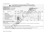
Table 1. Six digital and analog pins are easily accessed via RC headers on the SkyShield.
Standard
function
Control servos
Control cameras
Arduino
signal pins
D3, D5, D6, D9
A0, A1
Connections
used
G, V, S
G, V
Note: G = ground, V=voltage, S=signal (signal pins A0 and A1 are routed to the V headers, not the signal headers)
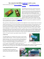
The following instructions are for SkyShields running a current Arduino
sketch (SkySweep version 2.xx) for controlling a Saturn V Rig. To
connect the Saturn V Rig to the SkyShield, four cables with male RC
servo connectors must be plugged in to the shield. Pay attention to
polarity when plugging in all connectors.
Power: The battery pack or case connects with a standard male RC
servo connector and plugs in to two pins on the SkyShield (“Batt”). The
black wire from the battery connects with the black (-) header, the red
wire connects with the red (+) header. Four fresh AAA alkaline batteries provide adequate power for the rig when
the temperature is above 60°F. Below 60°, six AAA are required (the voltage must remain above about 5.5 V).
Camera: The USB port of the Canon PowerShot should be connected to
the “A0” header on the SkyShield (“A1” is for a second camera or other
device). A custom cable is needed (mini USB B male to male servo
connector). Be sure to connect the black wire to the black header (G) and
the red wire to the red header (V). The third header pin (S) is not routed
and serves only to strengthen the physical connection. Switch the black
and red wires in the servo connector if required -- the wire ends are
designed to slip out of the black connector if the tiny locking tab is lifted.
Custom cable with mini USB to male
RC servo connector
Servo leads: Each servo comes with a three-wire lead with a three-pin male
RC servo connector. The tilt servo is controlled by digital pin D9 and plugs
into the header pins with the “D9” label. The pan servo is controlled by
digital pin D6 and plugs in to the header pins with the “D6” label. (To
remember this: there are three letters each in “six” and “pan,” and there are
four letters each in “nine” and “tilt.”) The dark (brown) servo wire must
connect with the black header (G).
Servos with male RC connectors
Page | 2
Configuration and use
Powering up
As soon as the SkyShield is powered on (battery or USB), the sketch will start to operate servos. If the servos are
connected, make sure you are prepared for one or both servos to start moving.
Cable management
The turning gears and Picavet cross of the Saturn V Rig will
happily snag servo wires and Picavet lines and wrap them
into a tangle. When testing and flying, keep the Picavet lines
away from the gears. Wrap the servo wires around the
frame and use the holes in the pan servo structure to route
the wires so they are not dangling or near the gears. When
the wrist strap of a camera is wrapped around the frame as
a lanyard, ensure that it cannot interfere with the gears.
Keep the pan gears free of cables, lines, and straps.
CHDK
At every pan/tilt position a pulse is sent to the USB port of the camera. Canon PowerShots running CHDK can be
configured to trigger the shutter when this pulse is detected. In the CHDK menu, under “CHDK settings/Remote
Parameters” select:
Enable Remote [] (selected)
Switch Type [OnePush]
Control Mode [Quick]
Enable Synch [ ] (not selected)
To access the CHDK menu on most (but not all) PowerShots do a quick-press of the Play button (triangle) then
press menu. To exit the CHDK menu do a quick-press of the Play button (longer presses of the Play button operate
the normal Play function).
Non-CHDK cameras
A third servo can be controlled to depress the shutter button of cameras which cannot be operated via USB. Digital
pins D3 or D5 are available for this via servo headers on the SkyShield. Cameras with an IR remote sensor can be
triggered with an IR LED operated by one of these extra pins. Both of these functions would require additional
hardware and a modified Arduino sketch.
Camera settings
Exposure: Typical settings that produce good aerial photos include fast shutter speed (1/640 or 1/800 second),
low ISO (80 to 200), mid-range f-stop (f/3 to f/8, avoid maximum aperture if possible), and focus locked on infinity
(or “infinity mode” if manual focus is not available). Most of these settings require that a PowerShot camera be in
“Program” mode, not “Auto” mode. Some cameras have a shutter priority mode (Tv) which keeps the shutter speed
high while adjusting f-stop to expose each photo properly. CHDK provides this feature on any PowerShot.
Fast or slow: More recent and higher end PowerShots can process each shot quickly and shoot faster than older or
cheaper PowerShots. It is important to experiment with your camera to determine if the fast or slow SkyShield
modes are more appropriate for your camera. With slower cameras and with fast cameras in some conditions
(dark days, or homogenous scenes when no manual focus is available) the camera will not be able to take the photo
before the next pan or tilt motion and that photo will be missed. Experimenting inside a room may not replicate the
Page | 3
results outside on a sunny day (when it is easier to focus, etc). Failure to focus quickly is a common cause of missed
photos, so use manual focus if it is available.
Field of view: The widest focal length of a typical PowerShot lens is 28mm (35mm equiv.). Some higher-end
PowerShots have a slightly wider 24mm (eq.) lens, and some PowerShots have a longer 37mm (eq.) lens. A wider
lens requires fewer photos in order for a complete 360° panorama to be stitched together. The SkyShield modes
allow about 40% overlap between adjacent photos if the designated focal length is used, and it takes between eight
and ten photos to cover 360°. Modes are available for each of these three focal lengths.
The autoKAP modes
An Arduino microcontroller like the Nano does not have an operating
system. A single program (sketch) can be loaded into its memory and
it will run every time the Arduino is turned on or reset. The sketch is
retained in memory until another sketch overwrites it. The basic
sketch loaded onto the SkyShield includes eight different routines
(“modes”) that operate the pan and tilt servos and send a pulse to the
camera. Any mode can be selected using the DIP switch. If a new mode
is selected, it will be implemented after the power is cycled on again
or the Arduino is reset (tactile button on the Nano). A mode will
continue to run as long as power is supplied.
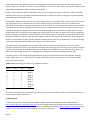
Press the reset button (white, center left)
on the Nano to activate a new mode that
has been selected with the DIP switch.
Most of the modes in the standard sketch (Modes 0 through 6) are designed to take photos which cover 360°
horizontally and several angles of tilt from about 45° from the zenith down to the nadir. One photo is taken at
every position (after the servos stop and pause), and there are 25 to 50 positions occupied before the routine
repeats. Some modes change the camera angle less between shots to allow more overlap between adjacent photos
and to accommodate longer focal length (less wide angle) lenses.
Five of these modes capture consecutive photos while panning 360° horizontally and then change the tilt angle and
pan 360° again. These modes decrease the number of pan positions from top to bottom. This is because for 360°
coverage fewer photos are needed when the camera is angled downwards (maybe only one is needed when the
camera is pointed at the nadir). This reduces the total number of photos and therefore the time required to take
them. The maximum number of pan positions per rotation differs to accommodate different focal length lenses,
and the pattern of decrease in pan positions is unique to each mode (Table 2). These patterns are defined in three
arrays early in the Arduino sketch and are easy to modify. The angles of each tilt position are also defined in arrays
which can be easily modified.
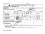
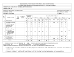
Table 2. Number of pan positions at each tilt angle for modes designed for lenses of three different focal lengths.
Tilt angle of camera
Mode
6
2, 3
0, 1
Lens focal
length (35mm
equivalent)
37 mm
28 mm
24 mm
Angled
upwards
10
9
8
Near
horizontal
10
9
8
Angled
down
9
8
6
Angled
down more
7
6
Nadir
4
3
3
Total
photos
taken
40
35
25
Note: Modes 0 and 1 have four tilt angles; modes 2, 3, and 6 have five tilt angles.
Modes 4 and 5 nest pans within tilts so each tilt angle is occupied consecutively and then the camera pans to the
next position and occupies all tilt angles again. The same number of photos is taken at each tilt position. These
modes are for a 28mm lens, so five tilt positions and nine pan positions are occupied for a total of 45 photos per
routine. For other lenses, the sketch can be modified.
Page | 4
Some modes wait longer between moves to accommodate cameras which process slower and cannot shoot as
quickly. Modes 0, 2, 4, and 6 are “slow” modes, and Modes 1, 3, and 5 are “fast” modes. The speed of a mode can be
adjusted by modifying the “delay” variables in the sketch.
Mode 7 covers only about 180° horizontally in order to focus on a particular part of the scene. Photos are taken
while the camera pans to the right and then back to the left, so photos are taken in a zigzag or serpentine pattern.
Sixteen photos in a 4x4 grid are taken.
Repeatability: Regular servos can return to a particular position (e.g., tilt angle) with some precision. The tilt servo
is a regular (micro) servo, but the pan servo on the Saturn V Rig is a continuous rotation servo which works
differently. This servo does not know what position it is in. To move to a new pan position, the servo moves with a
designated speed, duration, and direction. The exact arc of rotation cannot be predicted because the speed varies
somewhat with battery charge and acceleration. So the panning precision is somewhat variable. This is a minor
problem with 360° rotation because as long as the camera pans close to 360°, the entire scene will be captured in
photos. Testing is recommended with fresh batteries in the battery pack. If the rig does not pan the full 360° in the
designated number of steps, stronger batteries might be needed. If the rig pans more than 360° in the designated
number of steps make sure there will be sufficient overlap between photos for good stitching. To reduce the angle
of each pan move, the sketch will have to be edited, or try another mode.
For modes which are designed to cover less than 360°, the covered scene may drift with each row (each tilt
position). Panning 180° in four steps and then returning to the starting point in one large move is often inaccurate.
So after a few tilt positions, subsequent photos may not be pointed toward the scene of interest. Only Mode 7 is a
180° mode, and it captures photos in a zigzag pattern, taking photos while panning both left and right.
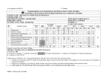
Selecting a mode: A DIP switch allows eight different modes to be selected. Select the desired mode using the
binary system below. A “1” indicates that a switch is in the ON position (switch is up). A “0” indicates the OFF
position (switch is down).
Table 3. Binary encoding of modes 0 to 7 with three switches.
DIP 1
0
0
0
0
1
1
1
1
DIP 2
0
0
1
1
0
0
1
1
DIP 3
0
1
0
1
0
1
0
1
Mode
Mode 0
Mode 1
Mode 2
Mode 3
Mode 4
Mode 5
Mode 6
Mode 7
To select a new mode, move the switches into the appropriate positions and press the reset button on the Nano or
turn the battery switch off then on.
Arduino sketch
To alter the parameters of the modes, the Arduino sketch can be edited. Install the Arduino IDE from here:
http://www.arduino.cc/en/Main/Software. This is a friendly integrated development environment and easy to
install and use. The sketch which runs on the Nano is available at the KAPtery (http://kaptery.com/guides/). Your
edited version of this sketch can be loaded onto the Nano via USB cable.
Page | 5
Calibration: Most modes have a lowermost tilt angle for capturing the nadir. In order for the camera to point
exactly vertically at this position, both the hardware and software might have to be adjusted. When using the
Saturn V Rig, the camera tray must be attached to the tilt servo spline so the lowermost tilt angle is as close to
vertical as possible (see Saturn V user manual). A final adjustment must be made by changing a value in the
Arduino sketch. At the beginning of the sketch, find the following code:
Servo tiltServo;
int tiltAngle5[]= {126, 98, 70, 42, 13};
int tiltAngle4[]= {126, 89, 52 13};
int tiltAngle3[]= {100, 70, 40};
// Assign tilt servo.
// ***Modify*** the following arrays if you want different tilt angles.
// Establish an array for five tilt positions upper to lower
// Establish an array for four tilt positions upper to lower
// Establish an array for three tilt positions upper to lower
The last value in the arrays is the lowermost tilt position (the values are degrees but the starting angle is
arbitrary). Change the value “13” (highlighted) to a smaller or larger value to change the nadir camera angle. The
number must be 0 or greater. Upload the newly edited sketch to the Nano and run the sketch to see if the angle is
correct (Mode 4 is good for this test because it points to the nadir sooner than other modes).
Power options
The battery case with the Saturn V Rig kits has an on/off switch which is the main operating switch in this system.
Battery power can be on at the same time the Nano is plugged into USB power. A voltage regulator on the
SkyShield outputs 5 volts and 1.5 amps with an input of up to 17 volts. So any power sources that provide between
6 and 17 volts can be used. Four fresh alkaline AAA batteries provide ample power for more than an hour of
operation when it is warm (60°F) but six AAA are recommended. Four rechargeable AAA batteries never have
sufficient voltage, but if six AAA are used, either alkaline or rechargeables should work. Old batteries can cause
erratic servo behavior. If servos are not doing what the sketch is instructing them to do, replace the batteries. Six
fresh batteries should last for a KAP flight of three or more hours (the limit has yet to be observed).
The power supplied by USB 2.0 is insufficient to run servos. When the SkyShield is powered only by USB, the
servos may not respond correctly to instructions in the sketch. So when loading and testing new sketches, make
sure there is battery power to the SkyShield in addition to or instead of USB power.
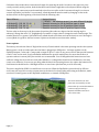
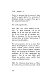
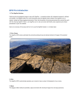
The Crown Point Fort, NY. This
panorama was stitched from nine
photos taken by a PowerShot S100 on
a Saturn V Rig operated by a
SkyShield autoKAP controller. It
covers about 180°.
Page | 6