1
UMC32+S DIY USB-SERIAL Controller
USER MANUAL
Firmware v1.0.0 / Hardware v1.1
©2008 – 2011 Hale Microsystems LLC, All Rights Reserved.
UMC32+S USB-Serial User Manual
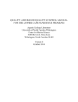
Product Description
The UMC32+S is based on Hale Micro‟s UMC32+ DIY USB-MIDI controller. Unlike the original MIDI version, the S or Serial version
provides users the ability to communicate with the device over a standard COM port. Communication with the device is achieved by
sending simple alphanumeric commands/parameters via a terminal emulator (ex: hyper term) or your own application or script. This
allows users a simple method for collecting data from external sensors, switches or turning on relays or actuators. Here are just a few
features available in the first revision of the firmware.
32 individually configurable I/Os
Multiple units can co-exist on the USB bus
Small printed circuit board (1.7” x 3.3”) allows creating portable end devices
Compatible with all versions of Mac OS X, Windows 7 / Vista / XP / 2000 and all versions of Linux
USB bus powered. A single USB cable handles power and data.
No firmware programming is necessary
A redesigned PCB with dedicated GND and VCC planes for enhanced signal integrity
I/O Configuration is now handled entirely by the configuration utility
Connector for external status LED, on board status LED is now blue
Standard USB TYPE B Connector
AUX I/O block for future expansion (TBD)
USB 2.0 Full Speed communication (12Mbit/sec)
RoHS Compliant (lead Free), manufactured to IPC-A-610 Rev. B, Class II
Mounting holes (#4 screw) near USB connector to provide additional support for USB insertion and removal
Individual selection of each I/O‟s corresponding hardware type including:
o Digital Input (active low) - For receiving messages from sensors with active low TTL outputs
o Digital Input (active hi) - For receiving messages from sensors with active high TTL outputs
o Analog Input (Raw)- 0-5V Analog Input, 12 bits (raw) (0 – 4095)
o Analog Input (Averaging) - 0-5V Analog Input, 11 bits Averaging filter (0 – 2047)
o Digital Output (active hi) – Useful for turning on LEDs or controlling external relays
Upgradeable firmware via USB using Windows (XP/Vista/Window7 32 & 64 bit) bootloader utility
* Please note that the UMC32+S (Serial) firmware is not compatible with the UMC32 or the UMC32+ USB-MIDI Model.
Before proceeding it is strongly recommended that you read and understand the precautions section of this manual. Please
pay attention to the section discussing the safe handling and how to avoid electrostatic discharge (ESD). Failure to observe
the recommendations may result in damage to your UMC32+S and void your warranty.
Overview
The process for setting up and testing your UMC is as follows:
Download and install CDC drivers from the Hale Micro website
Install terminal application
Send test commands to the UMC using application examples provided
Ensure that you are using the most recent manual and corresponding firmware, if not, install bootloader driver and bootloader
application, download the most recent manual and firmware from Hale website, and perform the firmware update of your UMC.
Create a custom application that will allow you to talk to your UMC and perform desired tasks.
Post questions to the “UMC32+S USB-Serial” section of the support forum located at http://forums.halemicro.com
Firmware v1.0.0, Hardware v1.1, Datasheet: 09/12/2011 6:25 PM / © 2008-20011 Hale Microsystems LLC, http://www.halemicro.com
2
UMC32+S USB-Serial User Manual
Windows CDC Driver Installation
Before connecting your UMC32+S to your PC, please download the UMC32+S_USB-Serial_CDC_Drivers.zip file located on the
UMC32+S product page at halemicro.com. Save and extract the ZIP file to a new folder on your desktop.
Connect the UMC32 to your PC. In the lower right corner of your screen Windows will report “Installing device driver software”. After a
few moments Windows will display a message stating “Device driver software was not successfully installed”. This message is
expected. Now go to your Start menu. Click on Control Panel. Click on Hardware and Sound and open Device Manager. Double click
on “Other devices” and double click on “UMC32+S USB-Serial” to bring up properties. Click on “Update Driver” and select “Browse my
computer for driver software.” Click the Browse button and find the “UMC32+_USB-Serial_CDC_Drivers” folder on your desktop.
Windows will show a message stating “Installing driver software” followed by a Security message. Verify that Hale Microsystems LLC is
the publisher and click the install button. You should see “Windows has successfully installed your driver software”, click Close. Click
close for properties as well. Back in the Device Manager should see “UMC32+S USB-Serial (COMx)” under ports (COM & LPT). Make
a note of this com port number, as this is what you will select later when opening a com port. At this time it should be noted that if you
change the USB port your UMC is connected to, you may be directed to install the driver, and this will likely cause windows to assign
the UMC a new COM port number. Once you have verified that the UMC shows up in your device manage r it is time to test it with a
terminal application.
Windows Bootloader Driver Installation
The UMC32+S is unique in that it allows new firmware revisions are release you can install them in your device by performing a
firmware update using the boot loader utility. To continue on and upgrade your firmware, please ensure that your UMC is disconnected
from your PC before proceeding. If you have anything connected to the 32 I/O‟s or other connections please remove them prior to
initiating a firmware update. Now place the supplied jumper across CN9. Whenever the UMC32+S is attached to your USB port it will
check to see if a jumper is placed on CN9. If so, it will enter a special boot loader mode. This bootloader mode requires installing an
additional driver so that the PC Bootloader application can perform firmware updates. Download the latest version of the driver and
bootloader utility from the halemicro.com website:
UMC32+S_USB-Serial_Bootloader.zip (Bootloader application for Windows)
UMC32+S_USB-Serial_Bootloader_Drivers.zip (Bootloader drivers)
UMC32+S_USB-Serial_DLD.zip (Firmware binary to upgrade UMC)
Save and extract the ZIP file to a new folder on your desktop. At this point you can re-connect the USB cable to your UMC. In the
lower right corner of your screen Windows will report “Installing device driver software”. After a few moments Windows will display a
message stating “Device driver software was not successfully installed”. This message is expected.
Go to your Start menu, click on Control Panel, click on Hardware and Sound and open Device manager. Double click On “Other
devices” and double click on “UMC32+S BootLdrUSBFSe_1.x” to bring up properties. Click on “Update Driver” and select “Browse my
computer for driver software.” Click the Browse button and find the “UMC32+_USB-Serial_Bootloader_Drivers” folder on your desktop.
Windows will show a message stating “Installing driver software” followed by a Security message. Verify that Hale Microsystems LLC
is the publisher and click the install button. You should see “Windows has successfully install ed your driver software”, click Close.
Click close for properties as well. Back in the Device Manager under “Universal Serial Bus controllers” you should see “UMC32+S
USB-Serial Bootloader Driver (3.4.6.000)”.
Now that your driver is installed you can launch the Bootloader utility “UMC32+S_USB-Serial_Bootloader_v1_x”. If you get an error
when launching the application check and make sure that “CyUSB.dll” is in the same directory as the app. Once the application
has loaded you should see a message at the bottom of the app indicating that the driver has been detected. Now click on select DLD
file to download. You should see the “Downloading….” Message, then after a minute or so a popup dialog will display “Downloa d
complete. You many now disconnect the USB cable from your UMC and remove the jumper on CN9.” Click OK, then disconnect the
USB cable from the UMC, and remove CN9. The firmware update is complete.
Windows Terminal Example
After installing the CDC driver we now want to install a terminal application. For this example we will be using the Tera Term 4.71
available at http://logmett.com/index.php?/download/download-tera-term-471-freeware.html. After installing, Launch TeraTerm, the new
Connection dialog will pop up. Select „Serial‟ and the COM port associated with “UMC32+S USB-Serial”, click OK. From here you can
jump ahead to the Terminal Setup Example to continue.
Firmware v1.0.0, Hardware v1.1, Datasheet: 09/12/2011 6:25 PM / © 2008-20011 Hale Microsystems LLC, http://www.halemicro.com
3
UMC32+S USB-Serial User Manual
Apple OS X / Generic Linux Terminal Setup Example
For OS X and Linux systems, no driver installation is necessary as the operating system provides the CDC class drivers. Simply
Connect the UMC to your system and it is ready to talk to with a terminal application. Screen is an application that comes preinstalled
on many Unix based systems and can be used to communicate with the UMC. We have found it to be preinstalled with Apple OS X as
well as Linux.
Using Screen on OS X
To use Screen on OS X you need to launch Terminal first before proceeding.
Terminal is located in: Macintosh HD/Applications/Utilities/
Once you are at the shell prompt you can begin.
Type: ls /dev/tty.*
This will display a list of device(s).
On our OS X machine the UMC shows up as /dev/tty.usbmodemfd521
Type: screen /dev/tty.usbmodemfd521 9600
From here you can jump ahead to the Terminal Setup Example to continue.
Using Screen on Linux
To use Screen on Linux (we use CentOs)
Type: dmesg | grep tty
On this machine the UMC shows up as /dev/ttyACM0
Type: screen /dev/ttyACM0 9600
From here you can jump ahead to the Terminal Setup Example to continue.
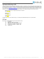
Terminal Setup Example:
Once your terminal app is running, hit enter and you should see the default prompt of „UMC32+S>‟. When using Screen, it is helpful to
configure the UMC so that the text output is easier to read.
First initialize the UMC to factory defaults.
Type: !rfd
Enable character echo so that we can see what we are typing:
Type: ste 1
Then we setup linefeeds for use with Screen (slc= set line control)
Type: slc 1
If you want these settings recalled on power up….
Type: !fdc
If you ever want to restore back to factory defaults (Also remember to use !fdc to save to flash ROM)
Type: !rfd
To see the current firmware version of the UMC….
Type: gdf
To see a list of available commands
Type: ?
To exit Screen hold down control and press A, then K and then y to exit.
Please note that the ste and slc commands are optional. Most users will want to configure their terminal application to communicate
with the UMC in its default mode (Echo off, Line feed as End of line character).
By now you will have noticed codes prefixed by an „S:‟ such as „S:0‟. These are the success codes. If there was an error in processing
a command those codes are prefixed by an ‟E:‟. See Return Code Summary for details.
Firmware v1.0.0, Hardware v1.1, Datasheet: 09/12/2011 6:25 PM / © 2008-20011 Hale Microsystems LLC, http://www.halemicro.com
4
UMC32+S USB-Serial User Manual
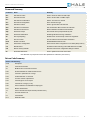
Command Summary
Command
Name
Summary
Gcv
Get Channel Value
Used to return the state of a UMC input
Scv
Set Channel Value
Used to set the state of a UMC Output
Gcc
Get Channel Configuration
Get the I/O Type for a channel
Scc
Set Channel Configuration
Set a channels I/O Type
Gdv
Get Device Values
Used to get the state of all channels
Gdc
Get Device Configuration
Get configuration data for device (All channels)
Gdf
Get Device Firmware rev
Returns firmware information and build date
Sdp
Set Device Prompt
Sets custom device prompt defined by user
Sdn
Set Device Notifications
Enables global device change notification
Slr
Set Loop Reporting
Enables return of internal loop counter for diagnostics
Slc
Set Line Control
Use for setting the line termination character(s)
Echo
Enable Local Echo
Enables/Disabled terminal echo
!fdc
Flash Device Configuration
Saves current device configuraton to non-volitile (flash) memory
!rst
Restart Device
Emulates the disconnecting of the USB cable from the UMC
!rfd
Restore Factory Defaults
Restores entire device configuration settings to default
!bl
Enter Booloader Mode
Used to update the firmware of the UMC
* The UMC32-S only responds to lower case alphanumeric characters ('0-9' and 'a-z')
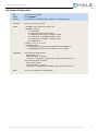
Return Code Summary
Return Code Summary
Code
Description
S:0
Command successful
S:1
Multiline return command successful
E:50
No data available for undefined channel type
E:51
Channel or parameter out of range
E:52
Invalid parameter or command
E:53
Incorrect number of parameters
E:54
Channel type is not an output!
E:55
Channel out of range (1 to 32)
E:56
Event notification not available for output types
E:57
Missing Parameter(s)
T:x
where x denotes the output channel (multi line return)
A:
Firmware revision info
C:x
Channel data
N:x x
Notification data
Firmware v1.0.0, Hardware v1.1, Datasheet: 09/12/2011 6:25 PM / © 2008-20011 Hale Microsystems LLC, http://www.halemicro.com
5
UMC32+S USB-Serial User Manual
App Example #1 (Reading data from a switch)
Apart from just typing commands and getting the firmware version of the device, the most common real world application involves
reading the state of a switch. In this example we will use the polling method to determine the state of a Tactile SPST switc h. Before
proceeding, please close your terminal application and disconnect the UMC from your PC as it will prevent any accidental shorting
while working with the hardware. Next, connect one pin of the SPST switch to the UMC‟s Ground and the other pin of the switch to
Channel #1 pin of the UMC (see UMC32+S I/O Pin Diagram for more info). Now we can reconnect the UMC, restart the terminal
application and open the COM port associated with the UMC32. You are now ready to configure the UMC and issue some commands.
First initialize the UMC to factory defaults:
Type: !rfd
Enable character echo so that we can see what we are typing:
Type: ste 1
Then we setup linefeeds for use with Screen (slc= set line control):
Type: slc 1
Setup UMC I/O channel for Digital Input w/Pullup (10) with notification on change disabled (0):
Type: scc 1 10 0
Save this configuration so that it is preserved when powered off:
Type: !fdc
Now you can issue the „Get Channel Value‟ command to read the state of the switch:
Type: gcv 1
Actuate the switch and see the result change as an example:
UMC32+S>gcv 1
C:1 1 <---- Switch Open
S:0
UMC32+S>gcv 1
C:1 0 <---- Switch Closed
S:0
App Example #2 (Reading data from a sensor)
For this example we use a Maxbotix MB1040 Ultrasonic sensor connected to input 1 on the UMC. The Maxbotix has a 0-5V analog
output that works well with the UMC‟s inputs. First we want to configure the UMC so that it can read an analog input and rep ort the
data as it comes in. In the previous example we used the polling method to check the state of the input. In this example we will
demonstrate the Notification method.
First initialize the UMC to factory defaults:
Type: !rfd
Enable character echo so that we can see what we are typing:
Type: ste 1
Then we setup linefeeds for use with Screen (slc= set line control):
Type: slc 1
Setup UMC I/O channel for analog input (filtered) with notification on change enabled:
Type: scc 1 50 1
Now turn on the global enable for notifications.
Type: sdn 1
You should now see a stream of random data in the form of „N:1 xxxx‟ which is normal.
Save this configuration so that it is preserved when powered off:
Type: !fdc
Now we want connect the sensor to the UMC. First we want to disconnect TeraTerm from the COM port (File> Disconnect),
Then unplug the USB cable from the UMC. Now connect the Ground and +5V from the UMC to the MB1040, then connect the AN line
of the MB1040 and connect it to the UMC‟s I/O #1 (see UMC32+S I/O Pin Diagram for more info). Now reconnect the USB cable to the
UMC. In Tera Term re-open the port (File>New Connection). Upon connection you see a stream of data from the MC1040 that
represents the distance from the object.
Firmware v1.0.0, Hardware v1.1, Datasheet: 09/12/2011 6:25 PM / © 2008-20011 Hale Microsystems LLC, http://www.halemicro.com
6
UMC32+S USB-Serial User Manual
App Example #3 (driving an LED)
Let say that we want to drive an LED that is connected to channel 1 of the UMC. First we want to ensure that we have the LED
connected correctly to the I/O Pin and that we have a series resistor in line with the LED. See the UMC32+S I/O Pin Diagram to find
pin 1 and ground on the UMC32. You‟ll want to connect the Anode of the LED to the I/O of the UMC, connect the Cathode of the LED
to your resistor (see http://led.linear1.org/1led.wiz for choosing your resistor) and connect the remaining resistor connection to Ground
(Labeled „G‟ in the pinout). Now that you have the hardware setup you can configure and prepare to turn the LED on and off.
First configure the I/O pin as a digital output with the scc command:
Type: scc 1 100 0
To turn the LED on:
Type: scc 1 1
To turn the LED off:
Type: scc 1 0
The digital output mode is also useful for turning on or off a high power Solid State Relay such as a Crydom D1D20.
I/O Types
Below are the currently available I/O types with this Firmware revision:
0……….I/O Disabled
10……...Digital input, Active Low with Pullup
11……...Digital Input, Active High / no Pullup (TTL Level)
50………Analog Input, 11 bits (filtered) Range 0 - 2047
51………Analog Input, 12 bits (raw)
Range 0 - 4095
100…...…Digital Output
Firmware v1.0.0, Hardware v1.1, Datasheet: 09/12/2011 6:25 PM / © 2008-20011 Hale Microsystems LLC, http://www.halemicro.com
7
UMC32+S USB-Serial User Manual
The following sections provide details for each UMC command.
Get Channel Value
Gcv
Usage:
Returns:
Get Channel Value
gcv <CHANNEL>
'C:<CHANNEL> <CHANNEL_VALUE>'
Description:
Used to return the state of a UMC input
Where:
<CHANNEL> is the UMC‟s I/O channel (1-32).
<CHANNEL_VALUE>
For digital types, the return is a „0‟ for off/low, or a „1‟ for on/high.
For analog types, the return is an integer
Example(s):
Read channel 1 input and return data
Send to UMC: „gcd 1‟
Return from UMC: „C:1 4082‟, where channel 1 reports a value of 4082 (decimal)
Read channel 12 input and return data
Send to UMC: 'gcd 12'
Return from UMC: 'C:12 104‟, where channel 12 reports a value of 104 (decimal)
Notes:
Channels configured as digital inputs shall respond with a 1 (on) or 0 (off).
Analog inputs shall respond with an unsigned integer.
Digital outputs will respond with their current output state.
Set Channel Value
scv
Usage:
Returns:
Set Channel Value (Digital Output type only)
scv <CHANNEL> <CHANNEL_VALUE>
'C:<CHANNEL> <CHANNEL_VALUE>'
Description:
Used to set the state of a UMC Output
Where:
<CHANNEL> is the UMC‟s I/O channel (1-32).
<CHANNEL_VALUE>
A „0‟ for off / low / 0 Volts, or a „1‟ for on / high / 5 Volts
Example(s):
Set channel 1 high
Send to UMC: „scv 1 1‟
Return from UMC: „S:0'
Set channel 23 low
Send to UMC: „scv 23 0‟
Return from UMC: „S:0'
Notes:
This command does not apply to channels configured as inputs.
Channel must be configured as an output with the SCC command prior to use.
Firmware v1.0.0, Hardware v1.1, Datasheet: 09/12/2011 6:25 PM / © 2008-20011 Hale Microsystems LLC, http://www.halemicro.com
8
UMC32+S USB-Serial User Manual
Get Channel Configuration
gcc
Usage:
Returns:
Get Channel Configuration
gcc <CHANNEL>
C:<CHANNEL> <CHANNEL_TYPE> <NOTIFY> <CHANNEL_DATA>'
Description:
Get the I/O Type for a channel
Where:
<CHANNEL> is the UMC‟s I/O channel (1-32).
<CHANNEL_TYPE> is:
0 - I/O Disabled
10 - Digital input, Active Low with Pullup
11 - Digital Input, Active High / no Pullup (TTL Level)
50 - Analog Input, 11 bits (filtered) Range 0 - 2047
51 - Analog Input, 12 bits (raw)
Range 0 - 4095
100 - Digital Output
<NOTIFY> is „on‟ / „1‟ or „off‟ / „0‟
<CHANNEL_DATA>
For analog types, the return is an integer between 0 and 4095 (raw)
For digital types, the return is a „0‟ for off/low, or a „1‟ for on/high
Example(s):
Get channel info about channel 1
Send to UMC: „gcc 1‟
Return from UMC: „T:1 100 0 0'
(Channel 1 is configured as a Digital output, notify is off, current value is 0)
Get channel info about channel 20
Send to UMC: „gcc 20‟
Return from UMC: „T:20 0 0 0'
(Channel 20 is configured as I/O Disabled, notify is off, current value is 0)
Notes:
See 'scc' for explanation of notify parameter.
Firmware v1.0.0, Hardware v1.1, Datasheet: 09/12/2011 6:25 PM / © 2008-20011 Hale Microsystems LLC, http://www.halemicro.com
9
UMC32+S USB-Serial User Manual
Set Channel Configuration
scc
Usage:
Returns:
Set Channel Configuration
scc <CHANNEL>
C:<CHANNEL> <CHANNEL_TYPE> <NOTIFY>'
Description:
Set a channels I/O Type
Where:
<CHANNEL> is the UMC‟s I/O channel (1-32).
<CHANNEL_TYPE> is:
0 - I/O Disabled
10 - Digital input, Active Low with Pullup
11 - Digital Input, Active High / no Pullup (TTL Level)
50 - Analog Input, 11 bits (filtered) Range 0 - 2047 (12 to 2038 *)
51 - Analog Input, 12 bits (raw)
Range 0 - 4095 (25 to 4077 *)
100 - Digital Output
<NOTIFY> is „on‟ / „1‟ or „off‟ / „0‟
<CHANNEL_DATA>
For analog types, the return is an integer between 0 and 4095 (raw)
For digital types, the return is a „0‟ for off/low, or a „1‟ for on/high
Example(s):
Set channel 1 configuration to Digital input w/Pullup, notify on
Send to UMC: „scc 1 10 1‟
Return from UMC: „N:1 1'
(Channel 1 is configured as a Digital input, notify is off, current value is 1)
Set channel 30 configuration to Digital input w/Pullup, notify on
Send to UMC: „scc 30 50 0‟
Return from UMC: „N:1 1'
(Channel 1 is configured as a Digital input, notify is off, current value is 1)
Notes:
When NOTIFY is enabled for a specific channel, the UMC will transmit the state of the channel‟s
input if it changed since last reported. *Due to variances in MCU internal voltage reference
the effective input range will vary slightly depending on internal MCU temperature.
Global device notification (sdn) must be enabled for Notify to report voltage changes on pin.
Get Device Value
Gdv
Usage:
Returns:
Get Device Value (All channels)
gdv'
'C:<CHANNEL> <CHANNEL_VALUE>'
Description:
Used to get the state of all channels
Where:
<CHANNEL> is the UMC‟s I/O channel (1-32).
<CHANNEL_VALUE>
A „0‟ for off / low / 0 Volts, or a „1‟ for on / high / 5 Volts
Example(s):
Set channel 1 high
Send to UMC: „gdv‟
Return from UMC: „C:1 38'
„C:2 55'
„C:3 1'
„S:1'
Notes:
Above example has channels 1 & 2 configured as analog inputs, and 3 as digital input.
Firmware v1.0.0, Hardware v1.1, Datasheet: 09/12/2011 6:25 PM / © 2008-20011 Hale Microsystems LLC, http://www.halemicro.com
10
UMC32+S USB-Serial User Manual
Set Channel Configuration
Gdc
Usage:
Returns:
Get Device Configuration
gdc
C:<CHANNEL> <CHANNEL_TYPE> <NOTIFY> <CHANNEL_DATA>'
Description:
Get configuration data for device (All channels)
Where:
<CHANNEL> is the UMC‟s I/O channel (1-32).
<CHANNEL_TYPE> is:
0 - I/O Disabled
10 - Digital input, Active Low with Pullup
11 - Digital Input, Active High / no Pullup (TTL Level)
50 - Analog Input, 11 bits (filtered) Range 0 - 2047
51 - Analog Input, 12 bits (raw)
Range 0 - 4095
100 - Digital Output
<NOTIFY> is „on‟ / „1‟ or „off‟ / „0‟
<CHANNEL_DATA>
For analog types, the return is an integer between 0 and 4095 (raw)
For digital types, the return is a „0‟ for off/low, or a „1‟ for on/high
Example(s):
Get channel values for device
Send to UMC: „gcv‟
Return from UMC:
T:1 50 0 294
T:2 50 0 351
T:3 10 0 1
T:4 0 0 0
T:5 0 0 0
T:6 0 0 0
……………………….
T:32 0 0 0
S:1
None
Notes:
Get Device Firmware Version
Gdf
Usage:
Returns:
Get Device Firmware
gdf
A:<FIRMWARE_TEXT>'
Description:
Returns firmware information and build date
Where:
<FIRMWARE_TEXT>
Firmware and build date information
Example(s):
To check the firmware version installed in UMC
Send to UMC: „gdf‟
Return from UMC: 'A:UMC32+ Serial v1.0.0 08/28/11 (C)2011 Hale Microsystems LLC'
Notes:
None
Firmware v1.0.0, Hardware v1.1, Datasheet: 09/12/2011 6:25 PM / © 2008-20011 Hale Microsystems LLC, http://www.halemicro.com
11
UMC32+S USB-Serial User Manual
Set Device Prompt
Sdp
Usage:
Returns:
Set Device Prompt
sdp <DEV_PROMPT>
S:0
Description:
Sets custom device prompt defined by user
Where:
<DEV_PROMPT>
Prompt cannot exceed 10 Alphanumeric characters. No spaces.
Example(s):
To set the Device prompt to SATURN
Send to UMC: „sdp SATURN‟
Return from UMC: 'S:0
SATURN>
Notes:
Prompt can be restored to default with !rfd command.
Set Device Notification
Sdn
Usage:
Returns:
Set Device Notification
sdn <STATE>
S:0
Description:
Enables global device change notification
Where:
<STATE> is „on‟ / „1‟ or „off‟ / „0‟
Example(s):
Enable notifications for entire device
Send to UMC: „sdn 1‟
Return from UMC: S:0 (Indicates success)
Notes:
This is the global enabler for all I/O notifications.
Set Loop Reporting
Slr
Usage:
Returns:
Set Loop Reporting
slr <STATE>
S:0
Description:
Enables return of internal loop counter for diagnostics
Where:
<STATE> is „on‟ / „1‟ or „off‟ / „0‟
Example(s):
Enable loop reporting for
Send to UMC: „slr 1‟
Return from UMC: S:0 (Indicates success)
Notes:
This turns on reporting of the UMCs internal scan loop counter. Each time the UMC
performs a scan of all enabled channels (1-32) this counter is incremented. The 32 bit
is reset to zero when „slr on‟ is received. This can be usedful for debugging and or
optimizing the performance of your application. The loop counter is appended to the
end of all return messages with values (IE gcv or gdv).
Firmware v1.0.0, Hardware v1.1, Datasheet: 09/12/2011 6:25 PM / © 2008-20011 Hale Microsystems LLC, http://www.halemicro.com
12
UMC32+S USB-Serial User Manual
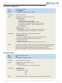
Set Line Control
slc
Usage:
Returns:
Set line control
slc <VALUE>
S:0
Description:
Use for setting the line termination character(s)
Where:
<VALUE> is 0, Line Feed (LF) character only (Default), ASCII 0x10
<VALUE> is 1, Carriage Return (CR) and Line Feed (LF) characters, ASCII 0x13, 0x10
<VALUE> is 2, Carriage Return (CR) character only (Default), ASCII 0x13
<VALUE> is 3, Line Feed (LF) and Carriage Return (CR), ASCII 0x10, 0x13
Example(s):
Set line control so that the UMC responds with a CRLF at the end of each line
Send to UMC: „slc 1‟
Return from UMC: S:0 (Indicates success)
Notes:
This allows the user a convenient way to configure the UMCs output such
that it is more readable. Linux or OS X terminal applications like SCREEN for example.
Set Terminal Echo
echo
Usage:
Returns:
Enables/Disabled terminal echo
ste <STATE>
S:0
Description:
Enables/Disabled terminal echo
Where:
<STATE> is '1' for on or '0' for off.
Example(s):
Enable UMC echo
Send to UMC: „ste 1‟
Return from UMC: S:0 (Indicates success)
Notes:
If you are seeing double characters you may want to disable echo as your terminal
application may already include local echo.
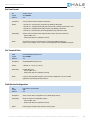
Flash Device Configuration
!fdc
Usage:
Returns:
Flash Device Configuration
!fdc
S:0
Description:
Saves current device configuraton to non-volitile (flash) memory
Example(s):
Write current device configuration to flash
Send to UMC: „!fdc‟
Return from UMC: S:0 (Indicates success)
Notes:
Executing this command also stores the device prompt.
Firmware v1.0.0, Hardware v1.1, Datasheet: 09/12/2011 6:25 PM / © 2008-20011 Hale Microsystems LLC, http://www.halemicro.com
13
UMC32+S USB-Serial User Manual
Restart UMC32+S
!rst
Usage:
Returns:
Restart device
!rst
S:0
Description:
Emulates the disconnecting of the USB cable from the UMC
Example(s):
Force UMC to restart
Send to UMC: „!rst‟
Return from UMC: S:0 (Indicates success)
Notes:
Upon execution of this command the UMC will wait approximately 10 seconds, then restart,
and re-enumerate with your computer. This should allow the user enough time to close
the open COM port and restart their application if necessary.
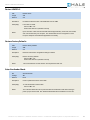
Restore Factory Defaults
!rfd
Usage:
Returns:
Restore factory defaults
!rfd
S:0
Description:
Restores entire device configuration settings to default
Example(s):
Restore to factory defaults
Send to UMC: „!rst‟
Return from UMC: S:0 (Indicates success)
Notes:
This command does not write to flash. That is performed with „!fdc‟.
Enter Bootloader Mode
!bl
Ussage:
Returns:
Start bootloader
!bl
None
Description:
Used to update the firmware of the UMC
Example(s):
To enter bootloader mode for UMC
Send to UMC: „!bl‟
Notes:
This command allows the user to place the UMC into bootloader mode without having to
place a jumper across CN9. See „Windows Bootloader Driver Installation‟ for more info.
Firmware v1.0.0, Hardware v1.1, Datasheet: 09/12/2011 6:25 PM / © 2008-20011 Hale Microsystems LLC, http://www.halemicro.com
14
UMC32+S USB-Serial User Manual
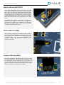
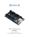
Status Indicator LED (CN11)
The indicator LED (LED1) can be found next to the USB
connector. This LED provides information about the state of the
UMC. When connected, your computer will recognize the UMC
and load the class compliant device driver that is provided by
your operating system. The LED will stay on until you open the
serial port associated with the device. At this point the LED will
flicker when traffic between the host application and the UMC
occurs.
The UMC32+S also provides a 2 pin header + (Anode) and –
(Cathode) for connecting to an external LED. It is important to
remember that in addition to the LED itself, you will need to
provide a current limiting resistor in series with your LED (Less
than 20mA is recommended at 5V dc).
Boot Loader Pin (CN9)
When the UMC is plugged into the USB port it first checks the
state of the shift pin. If it is pulled low (your switch is being held)
then the UMC will enter bootloader mode and prepare to accept
a firmware update. See the Windows Bootloader Driver
Installation section of this manual for instructions on how
upgrade your firmware.
Setup for USB Power(CN10)
The factory default has CN10 fitted with a jumper to provide
power via the USB bus. This also provides a convenient means
for measuring the current consumption of your final build. The
only other cases where this jumper should be removed is when a
UMC is connected to a linker board and is being used as a slave,
or when external power is being used as a Master.
Firmware v1.0.0, Hardware v1.1, Datasheet: 09/12/2011 6:25 PM / © 2008-20011 Hale Microsystems LLC, http://www.halemicro.com
15
UMC32+S USB-Serial User Manual
Aux Connector
The Aux connector is not implemented in this version of the
firmware. The intent of the I/O block is to allow for future
expansion.
General Precautions
The UMC is designed to protect against short circuits, over current conditions, transient voltages and electrostatic discharge. However,
we ask that you observe some simple guidelines when working with the UMC. Failure to do so may cause damage to your equipmen t
and/or void your product warranty.
o
Treat the UMC32 as you would any modern computer RAM and observe best practices for Electrostatic Discharge.
See: http://www.phys.cwru.edu/courses/p203/resources/ESDprocedure.pdf or
http://www.esda.org/esd_fundamentals.html for more info about ESD precautions.
o
Do not place a jumper or otherwise short circuit the ExtLED pins or the Ext 5V Power pins.
o
Do not solder any wires or attempt to make any modifications to the UMC directly.
o
Do not connect the “+V” (+5 Volts DC) terminal to G (Ground). When this occurs, it is commonly referred to as a
“short circuit”.
o
Always unplug the USB cable from the device before modifying connections on the UMC.
o
As with all electronic devices, observe proper ESD handling practices. Always handle the printed c ircuit board (PCB)
by the edges. Never touch the top or bottom. Failure to make sure you are ground
o
Never allow the UMC to touch a wet or conductive surface.
o
Do not use any external voltage source to power devices that are connected to the UMC.
o
The maximum recommended current per channel is 8mA.
o
You may use the +5V and Ground pins off each bank to power other devices such as LED‟s. However the maximum
recommended is 80mA.
o
As an additional precaution, we strongly recommend using a powered USB hub when experimenting with the device.
Once you have finalized your project, and are sure you do not have any short circuits , then you may connect the
UMC directly to your computer‟s USB input. This is especially important when interfacing with a laptop, as damage to
your laptop could be substantial.
o
This product is offered to the end user in a non-enclosed OEM form. It is the responsibility of the end user of this
product to ensure that they comply with local regulations pertaining to unintentional radio frequency emissions. In the
United States, this pertains to FCC rules and regulations, Part 15, Section B.
Firmware v1.0.0, Hardware v1.1, Datasheet: 09/12/2011 6:25 PM / © 2008-20011 Hale Microsystems LLC, http://www.halemicro.com
16
UMC32+S USB-Serial User Manual
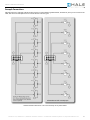
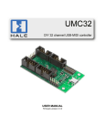
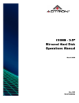
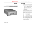
Example Connections
Although there are a seemingly infinite number of types of control elements (potentiometers, switches etc.) that you can connect to the
UMC, here are a few examples of how to connect the most common types.
* Please note that connection to +5V is not necessary for any SPST switch.
Firmware v1.0.0, Hardware v1.1, Datasheet: 09/12/2011 6:25 PM / © 2008-20011 Hale Microsystems LLC, http://www.halemicro.com
17
UMC32+S USB-Serial User Manual
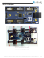
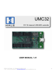
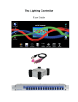
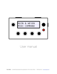
UMC32+S I/O Pin Diagram
UMC32+S with attached ribbon cable
Ribbon cable kit sold separately (Part # RIB50)
Firmware v1.0.0, Hardware v1.1, Datasheet: 09/12/2011 6:25 PM / © 2008-20011 Hale Microsystems LLC, http://www.halemicro.com
18
UMC32+S USB-Serial User Manual
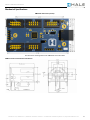
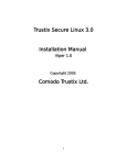
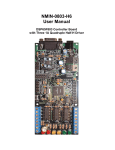
Mechanical Specifications
UMC32+S dimensions (inches):
The three 0.22” mounting holes for the UMC32+S are for #4 screws
USB Connector measurments (millimeters):
Firmware v1.0.0, Hardware v1.1, Datasheet: 09/12/2011 6:25 PM / © 2008-20011 Hale Microsystems LLC, http://www.halemicro.com
19
UMC32+S USB-Serial User Manual
Electrical Specifications
Exceeding the absolute maximum ratings below may cause permanent damage to the device.
Storage temperature:
-20ºC to + 70ºC
Operating temperature:
0ºC to + 50ºC
Operating voltage (power supplied via USB bus):
5.1 Volts DC max
Max recommended current per I/O channel
8mA
Maximum device current:
*500mA USB Bus Powered
Limited Warranty
Hale Microsystems LLC warrants this product to be free of manufacturing defects for a period of 90 days (USA only). If you
feel that there is a defect with your device, please email technical support with a detailed description of the problem:
[email protected]. In most cases we will simply issue a replacement. It is the responsibility of the customer to cover
the cost of shipping to and from Hale Micro. Devices shall only be accepted in original factory packaging. We will not accept
the return of any product that has been modified beyond factory condition. Any attempt to modify your unit shall void this
warranty.
Disclaimer
Neither the whole nor any part of the information contained herein or the product described in this datasheet may be adapted
or reproduced in any material or electronic form without the prior written consent of Hale Microsystems. This product and its
documentation are supplied on an as-is basis, and no warranty as to their suitability for any particular purpose is either made
or implied. Hale Microsystems LLC will not accept any claim for damages whatsoever arising as a result of use or failure of
this product. Your statutory rights are not affected. This product is not intended for use in any medical appliance, device or
system in which the failure of the product might reasonably be expected to result in personal injury. This document provides
preliminary information that may be subject to change without notice.
Windows is a registered trademark of Microsoft Corporation in the United States and other countries.
Firmware v1.0.0, Hardware v1.1, Datasheet: 09/12/2011 6:25 PM / © 2008-20011 Hale Microsystems LLC, http://www.halemicro.com
20