1
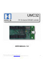
USER MANUAL 1.41
PCB rev 1 & 2, Firmware v1.41, Datasheet: 01/31/2009 10:10 AM
© 2007 - 2009 Hale Microsystems LLC, http://www.halemicro.com, email: [email protected]
1
Table of Contents
Product Description ............................................................................................................................... 3
Hardware Setup..................................................................................................................................... 4
Standard Mode (DIP Switch #10 = Off) ................................................................................................... 5
Extended mode (DIP Switch #10 = ON) ................................................................................................... 6
MIDI Channel / Device Driver Identification ........................................................................................... 7
Indicator LED ......................................................................................................................................... 7
Shift Pin / Firmware Update................................................................................................................... 7
Precautions ........................................................................................................................................... 8
Example Connections............................................................................................................................. 9
Pin Diagram ..........................................................................................................................................10
Mechanical Specifications .....................................................................................................................10
Electrical Specifications.........................................................................................................................11
Troubleshooting ...................................................................................................................................11
Limited Warranty..................................................................................................................................12
Disclaimer.............................................................................................................................................12
PCB rev 1 & 2, Firmware v1.41, Datasheet: 01/31/2009 10:10 AM
© 2007 - 2009 Hale Microsystems LLC, http://www.halemicro.com, email: [email protected]
2
Product Description
The UMC32 is an OEM/DIY product that allows Electronic Musicians, Multimedia Artists and Experimenters the ability
to create custom user interfaces to control any software application that supports the MIDI protocol. The UMC32
provides the essential core (microcontroller, power supply, USB functionality) to allow the user to easily implement
their choice of control elements (example: switches, pots and or faders). In short, the UMC32 will allow you to build
your own USB-MIDI controller.
Features
•
•
•
•
•
•
•
•
•
Easy to implement with minimal effort and little or no electronics experience.
32 analog and/or digital inputs provide MIDI note or continuous controller data to your host
application.
Small printed circuit board (1.6” x 2.7”) allows creating portable end devices
No programming is necessary. Onboard DIP switches allow simple configuration of MIDI note or
controller data.
USB bus powered. A single USB cable handles power and data.
Upgradeable firmware via Windows XP / Vista bootloader utility.
True plug-and-play (USB-MIDI class compliant drivers are provided by the operating system)
Compatible with Mac OS X 10.5.x(Leopard), Mac OS X 10.4.x(Tiger), Windows Vista / XP / 2000.
90 day limited warranty, 30 day money back guarantee (USA Only).
PCB rev 1 & 2, Firmware v1.41, Datasheet: 01/31/2009 10:10 AM
© 2007 - 2009 Hale Microsystems LLC, http://www.halemicro.com, email: [email protected]
3
Hardware Setup
Before proceeding it is strongly recommended that you read and understand the precautions section of this
manual. Failure to observe the recommendations may void your warranty. The UMC32 offers two operating
modes, analog and digital. By setting the onboard DIP switch appropriately, various control layouts can be
achieved. The UMC32 ships with the all DIP switches in the on position (all inputs digital). In order to change
from the default setting, please remove the protective tape (if present). It is important to note that all unused
channels be set to digital mode (factory default) in order to suppress spurious controller data be sent to your
host application.
Analog Mode:
Channels that are configured as analog inputs are sampled and converted into MIDI continuous controller
(CC#) messages and sent to your host application. Analog mode is usually the choice when connecting a
potentiometer or fader. For the sake of simplicity, each input channel maps directly to its corresponding
continuous controller (CC) number on MIDI channel 1. For example assume that input channel 1 on the UMC
has a fader connected to it and is configured for analog input. When the fader is changed it will output
controller messages on CC#01, MIDI channel 1.
Digital Mode:
Digital mode is usually selected to determine the state of a switch for triggering MIDI notes.
Channels that are configured for digital mode will output MIDI note data on channel 1. For example
when a button is pressed then a note on message will be sent, when the button is released a note off
message will be sent.
PCB rev 1 & 2, Firmware v1.41, Datasheet: 01/31/2009 10:10 AM
© 2007 - 2009 Hale Microsystems LLC, http://www.halemicro.com, email: [email protected]
4
Standard Mode (DIP Switch #10 = Off)
PCB rev 1 & 2, Firmware v1.41, Datasheet: 01/31/2009 10:10 AM
© 2007 - 2009 Hale Microsystems LLC, http://www.halemicro.com, email: [email protected]
5
Extended mode (DIP Switch #10 = ON)
Past UMC users should take note that the previous UMC32 datasheet did not specify the state at which DIP
10 should be set. For users who are updating an existing device please ensure that DIP10 is in the OFF
position prior to installing the 1.41 firmware. This will guarantee continued operation of the new firmware
with your existing setup. For new projects DIP 10 offers a pathway to new features in the device, to access
these features simply place the DIP in the ON position. Setting the DIP switched to combinations not listed
below will cause the device to simply blink on and off.
Diagnostic Mode
1
ON
2
ON
3
ON
DIP Switch
4
5
6
7
ON ON
ON ON
32 Channel Output Only Mode
OFF
ON
OFF
ON
OFF
ON
OFF
ON
OFF
ON
Even ch Digital w/ Odd ch LEDs
OFF
ON
OFF
ON
ON
ON
ON
ON
ON
ON
8
ON
9
ON
10
ON
Diagnostic Mode:
This is the test we use at the factory to make sure that the UMC’s hardware is to specification. To run this
test you’ll need to devise a way to connect channels 01-08 together, 09-16 together, 17-24 together, and 2532 together. DO NOT connect anything to the +5V or Ground lines as they are not used here. Now plug in
the USB cable to the UMC to provide power. The firmware will cycle thru and check each line to make
sure that there isn’t a defect with the PCB. If there is a problem with your hardware the LED will flash on
and off at fast. If the test was OK, it will flash slower at around ½ second.
32 Channel Output Only Mode:
In this mode all MIDI Note On/Off data that is received by the UMC32 is converted into logic level signal
on the UMC’s outputs. This is useful for connecting LED’s, transistors and relays. For normal/safe
operation it is recommended that the per channel load current (sourcing or sinking) per be less than 10mA.
C2(Note #36) = UMC Channel 01
C#2(Note #37) = UMC Channel 02
Etc…
* Please note that in this mode the Shift Pin has no effect in this mode.
Even ch Digital w/ Odd ch LEDs:
In this mode all Odd UMC channels are configured as digital inputs, while all even UMC channels are
configured as digital outputs. The even channels are for driving LED to help the user track the state of the
corresponding digital input. For instance, press the switch that is connected to input 1, the note on message
will be sent and the LED connected to channel 2 will turn on. Release the switch (to send the note off), the
LED will remain on. Press the same switch again, note on sent, LED turns off. Release the switch, note off
sent, LED stays off. The LED's will also update their on or off state according to the current shift mode.
Thus making the tracking of 64 on/off states is possible. To connect an LED to a UMC channel that is
configured as an output you MUST have a resistor in series with the LED and the channel output. It does
not matter if the resistor is connected to the anode or cathode of the LED. To find the correct resistance use
the online calculator provided by Linear Electronics at http://led.linear1.org/1led.wiz. The source voltage
parameter will be +5V (the UMC’s working voltage), the diode forward current should be 8mA, the diode
forward voltage will depend on your LED. Most red LED’s are 1.8 - 2.2 volts. See the datasheet of your
LED to obtain forward voltage parameters.
PCB rev 1 & 2, Firmware v1.41, Datasheet: 01/31/2009 10:10 AM
© 2007 - 2009 Hale Microsystems LLC, http://www.halemicro.com, email: [email protected]
6
MIDI Channel / Device Driver Identification
All UMC32’s ship with a default of MIDI channel 1. Changing the MIDI channel is possible by running the
firmware update utility and selecting the appropriate firmware. For example you purchased 2 UMCs and
want to connect them to the same PC/Mac. You decide that the first UMC is to be left at channel 1, while
the second you want configured to output on channel 2. To do this, you would first download the latest
firmware from the Hale website. The zip file will contain multiple firmware revisions with “.DLD”
extensions. Next download and install the UMC32’s firmware update utility, follow the directions provided
by the utility and select the appropriate firmware. In this case you would select “umc32_v141_Dev02.dld”,
This is the correct file for Device 2 / Midi channel 02. Apart from changing the MIDI channel, the firmware
also contains a unique USB Product ID (PID) as well as a unique Driver Name. As there are many
implementations by host applications and operating system driver this is a full-proof way of uniquely
identifying each UMC that is connected to your system.
Indicator LED
The indicator LED (LED1) can be found next to the USB connector. This LED provides information about the state of
the UMC. When connected, your computer will recognize the UMC and load the class compliant USB-MIDI class
device driver that is provided by your operating system. The LED will stay on until communication with your host
application begins. At this point the LED will flicker when MIDI traffic between the host application and the UMC
occurs.
Shift Pin / Firmware Update
When the Shift pin (P1[3] pictured below) is pulled to ground all MIDI note on/off messages will be
transposed by 32 notes. Simply place a single pole single throw normally open (SPST/NO) switch
between P1[3] and ground. The shift pin does not affect MIDI continuous controller (CC) data.
When the UMC is plugged into the USB port it first checks the state of the shift pin, if it is pulled
low (your switch is being held) then the UMC will enter bootloader mode and prepare to accept a
firmware update. Information regarding firmware updates will be made available on our website at
http://www.halemicro.com
PCB rev 1 & 2, Firmware v1.41, Datasheet: 01/31/2009 10:10 AM
© 2007 - 2009 Hale Microsystems LLC, http://www.halemicro.com, email: [email protected]
7
Precautions
The UMC is designed to protect against short circuits, over current conditions, transient voltages and
electrostatic discharge. However, we ask that you observe some simple guidelines when working with
the UMC. Failure to do so may cause damage to your equipment and/or void your product warranty.
o
Do not solder any wires or attempt to make any modifications to the UMC directly.
o
Do not connect the “+V” (+5 Volts DC) terminal to G (Ground). When this occurs, it is commonly
referred to as a “short circuit”.
o
Always unplug the USB cable from the device before modifying connections on the UMC.
o
As with all electronic devices, observe proper ESD handling practices. Always handle the printed
circuit board (PCB) by the edges, never touch the top or bottom.
o
Never allow the UMC to touch a wet or conductive surface.
o
Do not use any external voltage source to power devices that are connected to the UMC.
o
You may use the +5V and Ground to power other devices such as LED’s however the maximum
recommended load current per pin is 50mA.
o
As an additional precaution, we strongly recommend using a powered USB hub when experimenting
with the device. Once you have finalized your project, and are sure you do not have any short circuits
then you may connect the UMC directly to your computer’s USB input. This is especially important
when interfacing with a laptop, as damage to your laptop could be substantial.
o
This product is offered to the end user in a non-enclosed OEM form, it is the responsibility of the end
user of this product to ensure that they comply with local regulations pertaining to unintentional radio
frequency emissions. In the United States, this pertains to FCC rules and regulations, Part 15,
Section B.
PCB rev 1 & 2, Firmware v1.41, Datasheet: 01/31/2009 10:10 AM
© 2007 - 2009 Hale Microsystems LLC, http://www.halemicro.com, email: [email protected]
8
Example Connections
Although there are a seemingly infinite number of types of control elements (potentiometers, switches etc.)
that you can connect to the UMC, here are a few examples of how to connect the most common types.
PCB rev 1 & 2, Firmware v1.41, Datasheet: 01/31/2009 10:10 AM
© 2007 - 2009 Hale Microsystems LLC, http://www.halemicro.com, email: [email protected]
9
Pin Diagram
Mechanical Specifications
Please note that an alternative method to mounting the UMC to your enclosure via screws and standoffs is to
simply use double backed 3M VHB tape. Be sure that everything is working correctly before affixing to
chassis as any attempt to remove UMC affixed via from the chassis will place stress on the circuit board.
Regardless of the mounting method you choose, please take care that the exposed solder joints on the
bottom of the UMC do not make contact with your enclosure.
PCB rev 1 & 2, Firmware v1.41, Datasheet: 01/31/2009 10:10 AM
© 2007 - 2009 Hale Microsystems LLC, http://www.halemicro.com, email: [email protected]
10
Electrical Specifications
Exceeding the absolute maximum ratings below may cause permanent damage to the device.
• Storage temperature:
-20ºC to + 70ºC
• Operating temperature:
0ºC to + 50ºC
• Operating voltage (power supplied via USB bus):
5.4 Volts DC max
• Max recommended current per channel
8mA
• Maximum device current:
*200mA (R1 & R2 PCB’s with a “C” PTC)
• Maximum device current:
*250mA (R1 & R2 PCB’s with a “D” PTC)
• Maximum device current:
*500mA (R2 PCB’s with a “F” marked PTC)
*Check the component marking for PTC1
Troubleshooting
Here is a list of common questions we anticipate you may run into. We will periodically add to this as new
questions arise.
Q1:
A few pots are generating data even though I’m not moving them.
Verify that the pots are clean (CAIG Labs DeoxIT D5 works very well). If you have long wires
consider making them shorter. Generally speaking you should try to keep wire lengths as short as
possible. You might also try placing a 0.1uF capacitor across the power and ground inputs of your
potentiometer or fader. (Example: Digikey.com # BC1084CT-ND).
Q2:
Adjacent channels appear to affect one another.
Check the resistance with your multi-meter between the signal inputs of each channel. It should read
at least 1 Mega ohm. Also verify that your DIP switch pack is set correctly. Channels with switches
attached to them should be set for digital. Channels with fader or rotary potentiometers should be set
for analog mode. All unconnected channels should be set for digital mode.
Q3:
My MIDI application is seeing a lot of spurious controller data from the UMC, I do not have any
control elements connected to those channels.
Each time the USB is plugged into the UMC, it checks the state of the DIP pack to set each channel
to analog or digital mode. Channels that are left “floating” or in an undetermined state will generate
noise unless that are pulled high or low with an external resistor. Any channel that is set for analog
mode must be connected to a source (potentiometer) or it must be connected to a 10K resistor that is
connected to ground or +5 volts. Double check the DIP switches to confirm that they are set correctly
then restart the UMC.
Q3:
I plug the UMC into my USB port but it appears to be dead.
Disconnect the UMC from the USB bus immediately and check for any short circuits. Reboot your
computer and/or power cycle your USB hub. Make sure that the Shift pin (P1[3]) is not connected
when connecting the USB cable as this will cause the unit to startup in the bootloader mode.
Q4:
What to do when you receive an OS error about a surge of a USB device.
This generally happens when the user short circuits the +5V and power lines. See Q3 for remedy.
Q5:
When I turn a pot one way (clockwise), my application turns it another (counter clockwise).
Swap the V+ and G lines on your potentiometer, or perform a controller invert in your host software.
Q6:
If I disconnect the UMC while my host application is running, then re-connect again the host
does not see the UMC.
In our testing, Mac OS X had no problems with this. Depending on the application under Windows
XP you may need to re-launch your host application.
Q7:
How do I change the default MIDI output mapping ?
Since the UMC will always be connected to a computer and since most modern MIDI host
applications have a “Learn” function we felt that this option was unnecessary. If customer feedback
on this issue is strong we can provide a firmware update and or a utility.
PCB rev 1 & 2, Firmware v1.41, Datasheet: 01/31/2009 10:10 AM
© 2007 - 2009 Hale Microsystems LLC, http://www.halemicro.com, email: [email protected]
11
Limited Warranty
Hale Microsystems LLC warrants this product to be free of manufacturing defects for a period of 90 days
(USA only). If you feel that there is a defect with your device, please email technical support with a detailed
description of the problem: [email protected]. In most cases we will issue a replacement. Please note
that the unit must be shipped back in its original packaging and be in original saleable condition. We will not
accept the return of any product that has been modified beyond factory condition.
Disclaimer
Neither the whole nor any part of the information contained herein or the product described in this datasheet
may be adapted or reproduced in any material or electronic form without the prior written consent of the
copyright holder. This product and its documentation are supplied on an as-is basis, and no warranty as to
their suitability for any particular purpose is either made or implied. Hale Microsystems LLC will not accept
any claim for damages whatsoever arising as a result of use or failure of this product. Your statutory rights
are not affected. This product is not intended for use in any medical appliance, device or system in which the
failure of the product might reasonable be expected to result in personal injury. This document provides
preliminary information that may be subject to change without notice.
PCB rev 1 & 2, Firmware v1.41, Datasheet: 01/31/2009 10:10 AM
© 2007 - 2009 Hale Microsystems LLC, http://www.halemicro.com, email: [email protected]
12