1
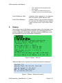
Web Transmitter Instruction Manual Revision 1.3 July 29th, 2011 Rudy Boonstra WebTransmitter User Manual 1. Introduction The WebTransmitter has been developed to copy numerical data from the Internet seamlessly into a control system as a 4-20mA signal. Once in the control system, such as a Programmable Logic Controller (PLC), Distributed Control System (DCS), or Basic Process Control System (BPCS), the data may be utilized and displayed on the Human Machine Interface (HMI) to provide “near real-time” information to operations. The process of coping data from the Internet is often referred to as scraping. Typically, data published on the Internet is copyrighted, and, therefore, it is the users responsibility to contact the owner of the data being copied to obtain permission. 2. Contact Information Additional information as well as firmware updates can be obtained from the following: 3. Internet: http:/www.webtransmitter.com Mail: Rudy Boonstra 95 Cougar Ridge Heights SW Calgary, Alberta T3H 4X5 Email: [email protected] System Requirements To properly implement the WebTransmitter, the following minimum requirements are required: Power: 15-30Vdc Network: The RJ45 will need to be connected to a network that provides the device with an IP address via DHCP and has direct access to the Internet. Firewalls and Proxy Servers that either modify the header or require authentication may prevent the WebTransmitter from functioning properly. Control System: A minimum of one 4-20mA analog input is required in the control system. This input must either be active such that it internally supplies the loop with approximate 24Vdc or passive complete with an external 24Vdc power supply. The maximum loop voltage is 36Vdc and the minimum loop voltage is 7.5Vdc, but 24Vdc is recommended and should be specified. Additionally, the following optional features may be utilized: WebTransmitter_UsersManual_v1_3.docx Page 2 of 7 WebTransmitter User Manual Control System: A second 4-20mA analog input, the same as above, may be used. A set of dry contacts, normally open, are included on the WebTransmittter. The default function for these dry contacts, which are rated for 5A at 30Vdc, are to provide a discrete input into the control system so that it can monitor the health of the WebTransmitter. Each time the WebTransmitter queries the Internet, the contacts close. Note that optional functionality can be made available for these dry contacts. The control system can utilize a relay to reset the board. In the unlikely event that the WebTtransmitter is not responding properly, as detected by the dry contacts above, the WebTransmitter can be remotely reset. Display: An optional LCD Display is available to provide status information of the WebTransmitter. Note that the display may be plugged in or removed while the WebTransmitter is power up and functioning. External Switches: External switches are available that mimic the functionality of on board switches SW3 and SW4. 4. Consumable Parts The WebTransmitter has the following consumable parts. They can either be sourced directly by the user or through R Engineering Inc. Battery: CR2032 3Vdc Lithium Ion Coin Cell Battery When this battery drops below ~2.9Vdc, and the board is without power via the terminal strip, the internal memory settings may be reset to default. Versions 0.x may need to be reprogrammed as via the internal WEB server. Versions 1.x and newer have a configuration file that is stored on the WEB as an .XML file; system memory is only used when this file is not available. Fuses: Main Board Power 4-20mA Inputs (2x) WebTransmitter_UsersManual_v1_3.docx – LittelFuse 154 Series 2A – LittelFuse 154 Series 100mA Page 3 of 7 WebTransmitter User Manual 5. External Connections The external connections are made via the ten (10) terminal Phoenix Contact connection header J2, as shown in Figure 1 below: Figure 1: Wiring Diagram For Loop B, if you have the optional external switch installed in SW4, the light will go on when there is loop power available. For Loop A, if you have the optional external switch installed in SW3, the light will go on when there is loop power available. For both Loop A and Loop B, if the control system does not see a signal, the external switch LED, if installed, may be used to indicate that there is loop power. If the switch is not installed, and it is believed that all the connections have been made properly, one can verify that the corresponding 100mA fuse (Loop A = F2 and Loop B = F1) has not blown open. If SW2 is on with 15-30Vdc power applied to terminals 0 and 1 (+ and – for PWR), the green LED labeled D4 should illuminate. If it does not light up, then the 2A fuse F3 may have blown open or the polarity may be reversed. 6. Network Connection When you have a proper network connection and the WebTransmitter is properly powered up, you should see activity on the small green LEDs on located adjacent to the RJ45 connector. As soon as the WebTransmitter is powered up, it will try to obtain an IP address from the network DHCP server. After an IP address has been assigned, the WebTransmitter will WebTransmitter_UsersManual_v1_3.docx Page 4 of 7 WebTransmitter User Manual download the configuration file. If the system clock is not properly set, the system clock is adjusted based on the time specified in the returned http header with the config file. At this point, the WebTransmitter is ready and will start the perpetual loop of obtaining WEB data every X minutes, where X is defined in the system configuration (typically every five minutes or 300,000 msec). 7. User Buttons There are five user buttons on the WebTransmitter, as follows: Label Function SW1 On board reset SW2 Turn power on Optional SW3 SW4 SW5 Initiate WEB query Display system info Register MAC address and IP address Optional Optional No system External Switch No Notes This feature is also available by connecting J2 terminals 2 and 3 together. Shorting block required if there is no optional switch Require optional display In cases where the WebTransmitter is mounted with optional switches and the on-board switches are not accessible, the functions of SW5 can be obtained by pressing SW3 and SW4 simultaneously. Note that if you press the SW5 switch twice before a poll is initiated, the unit will do a soft reset. This is useful to force the unit to re-load the configuration .XML file should it be changed. The display is instrumental in allowing the user to watch the configuration parameters, and shows both the system values as well as the new values loaded from the configuration file. 8. System Configuration Mode The configuration .xml file can only be altered by Rudy Boonstra as they are stored on the http://www.webtransmitter.com web site. The following parameters are available for adjusting: Loop Time - duration between polls; default value of five minutes or 300,000 msec Loop A Type - determines what data is to be obtained from the Internet, as listed below • WebTransmitter_UsersManual_v1_3.docx SMP - AESO System Marginal Electricity Price (C$/MWhr) Page 5 of 7 WebTransmitter User Manual 9. • NGX - Natural Gas Exchange AECO Gas Price (C$/GJ) • E+3 - AESO Forecasted Electricity Price (C$/MWhr) Three (3) Hours Ahead Forecast Loop A Maximum Value - maximum value expected to be obtained from the Internet; default value is 1000 Loop A Error Maximum - number of times in a row a bad value may be read from the WEB before the 4-20mA output is driven to the “Loop A Error Value” state. Display Upon startup, the unit will display a message similar to the following on the on the display, first obtaining an IP address, then downloading the most current configuration (if possible), and lastly initiating a WEB query to poll the information as per the downloaded configuration: 15:10:36 Activate network connection... 15:10:41 Obtain configuration info... Checksum 0000 > 771d Loop Time 300000 > 300000 A 1 1000 20 400 > 1 1000 20 400 B 2 1000 20 400 > 1 1000 20 400 NGX Access ******** > ********* Timezone -7 > -7 15:10:42 Initialized; get SMP & NGX data 15:10:44 SMP=$ 50.00 NGX=$ 5.00 000 000 Figure 2: Display – Start Up When the SW4 button is pressed, the system information is displayed: Version 1.D System Clock 2011/07/29 15:10:52 System Uptime 13 02:34:21 MAC is 00:00:00:00:00:00 IP is 000.000.000.000 Figure 3: Display – System Information WebTransmitter_UsersManual_v1_3.docx Page 6 of 7 WebTransmitter User Manual When the SW5 button is pressed once, the IP address is registered on the WebTransmitter.com database. This option is provided to provide additional troubleshooting information and allow confirmation that the WebTransmitter is able to and alow the data is updated in the http://www.webtransmitter.com database and is displayed. R Engineering Inc – S/N 7 at F/W 1.D Installed 2011-06-22 22:52:36 DB Updated 2011-07-29 15:11:44 Figure 4: Display – Network Information Figure 5: Database Matches Board Data 10. Document Version Information Version Comments 1.3 Rewritten for 1.x firmware 1.2 Updated for calibration mode and updating IP data to the database 1.1 Updated for 4-20mA diagnostic mode 1.0 Original Version WebTransmitter_UsersManual_v1_3.docx Firmware 1.D 0.1.P Author RJB RJB Date 2011.07.29 2009.05.21 0.1.M RJB 2009.04.26 0.1.K RJB 2009.03.14 Page 7 of 7