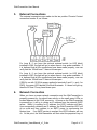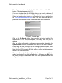
1
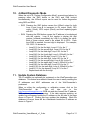
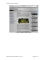
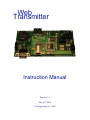
Web Transmitter Instruction Manual Revision 1.2 May 21st, 2009 R Engineering Inc., 2009 WebTransmitter User Manual 1. Introduction The WebTransmitter has been developed by R Engineering Inc. to copy data from the WEB seamlessly into a control system as a 4-20mA signal. Once in the control system, the data can be either merely displayed on the Human Machine Interface (HMI) or used in logic as a Process Variable (PV). The process of coping data from the Internet or WEB is often referred to as scraping. Typically, data published on the WEB is copyrighted, and, therefore, it is the users responsibility to contact the owner of the data being copied to obtain permission. 2. Contact Information Additional information as well as firmware updateds can be obtained from the following: 3. Internet: http:/www.webtransmitter.com Mail: R Engineering Inc. Attn: Rudy Boonstra 95 Cougar Ridge Heights SW Calgary, Alberta T3H 4X5 Email: [email protected] System Requirements To properly implement the WebTransmitter, the following minimum requirements are required: Power: 15-30Vdc Network: The RJ45 will need to be connected to a network that provides the device with an IP address via DHCP and has direct access to the Internet. Firewalls and Proxy Servers that either modify the header or require authentication may prevent the WebTransmitter from functioning properly. Control System: A minimum of one 4-20mA analog input is required in the control system. This input must either be active such that it internally supplies the loop with approximate 24Vdc or passive complete with an external 24Vdc power supply. The maximum loop voltage is 36Vdc and the minimum loop voltage is 7.5Vdc, but 24Vdc is recommended and should be specified. WebTransmitter_UsersManual_v1_2.doc Page 2 of 11 WebTransmitter User Manual Additionally, the following optional features may be utilized: Control System: A second 4-20mA analog input, the same as above, may be used. A set of dry contacts, normally open, are included on the WebTransmittter. The default function for these dry contacts, which are rated for 5A at 30Vdc, are to provide a discrete input into the control system so that it can monitor the health of the WebTransmitter. Each time the WebTransmitter queries the Internet, the contacts close. Note that optional functionality can be made available for these dry contacts. The control system can utlize a relay to reset the board. In the unlikely event that the WebTtransmitter is not responding properly, as detected by the dry contacts above, the WebTransmitter can be remotely reset. Display: An optional LCD Display is available to inform on the status of the device. External Switches: External switches are available that mimic the functionality of on board switches SW3 and SW4. 4. Consumable Parts The WebTransmitter has the following consumable parts. They can either be sourced directly by the user or through R Engineering Inc. Battery: CR2032 3Vdc Lithium Ion Coin Cell Battery When this battery drops below ~2.9Vdc, and the board is without power via the terminal strip, the internal memory settings may be reset to default and need to be reprogrammed. Fuses: Main Board Power 4-20mA Inputs (2x) WebTransmitter_UsersManual_v1_2.doc – LittelFuse 154 Series 2A – LittelFuse 154 Series 100mA Page 3 of 11 WebTransmitter User Manual 5. External Connections The external connections are made via the ten position Phoenix Contact connection header J2, as follows: For Loop B, if you have the optional external switch (or LED block) installed in SW4, the light will go on when there is loop power available. If it is believed that all the connections have been made properly, one can verify that the 100mA fuse F1 has not blown open. For Loop A, if you have the optional external switch (or LED block) installed in SW3, the light will go on when there is loop power available. If it is believed that all the connections have been made properly, one can verify that the 100mA fuse F2 has not blown open. If SW2 is on with 15-30Vdc power applied to terminals 0 and 1 (+ and – for PWR), the green LED labeled D4 should illuminate. If it does not light up, then the 2A fuse F3 may have blown open. 6. Network Connection When you have a proper network connection and the WebTransmitter is properly powered up, you should see activity on the small green LEDs on located adjacent to the RJ45 connector. As soon as the WebTransmitter is powered up, it will try to obtain an IP address from the network DHCP server. While it is waiting for IP address, the LED1 indicator will flash. Upon successfully obtaining an IP address, the WebTransmitter LED1 will go on solid and then connect to an SMTP server to synchronize the system time. If an SMTP servier is reached, the LED2 indicator will turn on. At this point, the WebTransmitter will then start the perpetual loop of WebTransmitter_UsersManual_v1_2.doc Page 4 of 11 WebTransmitter User Manual obtaining WEB data every X minutes, where X is defined in the system configuration (typically every five minutes or 300,000msec). 7. User Buttons There are five user buttons on the WebTransmitter, as follows: Label Function SW1 On board reset SW2 Turn power on Optional SW3 SW4 SW5 Initiate Web query Display system info Configuration Mode Optional Optional No system External Switch No Notes This feature is also available by connecting J2 terminals 2 and 3 together. Shorting block required if there is no optional switch Require optional display In cases where the WebTransmitter is mounted with optional switches and the on-board switches are not accessible, configuration mode can be obtained by pressing SW3 and SW4 simultaneously. 8. System Configuration Mode A Web Browser can be used to modify the configuration of the WebTransmitter. First, the WebTransmiter needs to be put into “System Configuration Mode”. Either pressing SW5 or pressing both SW3 and SW4 simultaneously will stop the perpetual query cycle and place the WebTransmitter in “System Configuration Mode”. If the optional display is installed, the IP address will be shown. While in “System Configuration Mode”, the LED1 indicator will flash. Use an internet browser on the same network as the WebTransmitter and type the IP address into the address bar. Note that the WebTransmitter times out after a period of time, and resets so that it can not be inadvertently left in config mode. If the correct address is entered, the WebTransmitter HTTP server will respond with a page similar to Figure 1. WebTransmitter_UsersManual_v1_2.doc Page 5 of 11 WebTransmitter User Manual Figure 1: Configuration Page Note that this is for firmware version 0.1.P and that future firmware versions may look slightly different and / or have additional configuration settings. There WebTransmitter can download data from either one or two of the following three sites: o SMP – AESO System Marginal Price (C$/MWhr) o NGX – Natural Gas Exchange AECO Gas Price (C$/GJ) o E+3 – AESO Forecasted Electricity Price (C$/MWhr) Three (3) Hours Ahead Forecast WebTransmitter_UsersManual_v1_2.doc Page 6 of 11 WebTransmitter User Manual Enter the password to enable the Update Values button and the Encode button. The default password is 1111. If you are using data from the NGX Web site, you will need to obtain an ID / password combination from the NGX, which then must be encoded. Utilize the Encode button to bring up a “Encode Tool” pop up window from the http://www.webtransmitter.com Web site and enter the an ID / password combination as follows in the Raw Value field: id:password Figure 2: Encode Page Click on the Re-Encode button, then copy this text string into the Gas Access field on the configuration page, and finally close the pop up window. After all of the configuration modifications are complete, then click the Update Values button to write these new values to the WebTransmitter. A new page will load confirming that the changes were successful, which will then forward to the configuration page with the new values shown. Note that the LED2 indicator will flash once to confirm that data has been written to the WebTransmitter. One can either make further adjustments if required, enter calibration mode (see Section 9), or click the Exit button. Clicking on the Exit button will cause the WebTransmitter to reset and then operate with the new configuration settings. WebTransmitter_UsersManual_v1_2.doc Page 7 of 11 WebTransmitter User Manual 9. 4-20mA Calibration Mode The Web Browser can also be used to calibrate the 4-20mA outputs. The default values for the 12 bit DAC are: o -2mA – 400 (Denotes an error signal to the control system) o 4-mA – 800 (0%) o 20mA– 4000 (100%) The screen capture in Figure 3 shows the + and – buttons that can be used to update each of these values. Additionally, when you update the calibration, you can drive the output to a preset value to assist in the calibration. These values can be verified by using the 4-20mA Diagnostic Mode, as detailed in Section 10. Figure 3: Calibration Page WebTransmitter_UsersManual_v1_2.doc Page 8 of 11 WebTransmitter User Manual 10. 4-20mA Diagnostic Mode When the unit is in “System Configuration Mode” as mentioned above, by pressing either the SW5 button or the SW3 and SW4 buttons simultaneously, the 4-20mA ouputs can be used for further diagnostics using SW3 and SW4. o SW3 Pressing the SW3 button causes the 4-20mA output for both Loop A and Loop B to increment to 0% output (4mA), 50% output (12mA), 100% output (20mA), and then repeating again with 0%. o SW4 Pressing the SW4 button causes the IP address to be displayed with the outputs. Loop B first toggles to display the digit number, followed immediately by Loop A to display the value. Both of these outputs need to be scaled 0% to 100%. Each time SW4 is pressed, the next digit is displayed. For example, 192.168.0.1 is shown as: o o o o o o o o o o o o Loop B 1% for the first digit, Loop A 1% for the ‘1’ Loop B 2% for the second digit, Loop A 9% for the ‘9’ Loop B 3% for the third digit, Loop A 2% for the ‘2’ Loop B 4% for the fourth digit, Loop A -250mA% for the ‘.’ Loop B 5% for the fifth digit, Loop A 1% for the ‘1’ Loop B 6% for the sixth digit, Loop A 6% for the ‘6’ Loop B 7% for the seventh digit, Loop A 8% for the ‘8’ Loop B 8% for the eighth digit, Loop A -250mA% for the ‘.’ Loop B 9% for the ninth digit, Loop A 0% for the ‘0’ Loop B 10% for the tenth digit, Loop A -250mA% for the ‘.’ Loop B 11% for the eleventh, Loop A 1% for the ‘1’ Repeat back with the first digit 11. Update System Database The IP address can optionally be registered on the WebTransmitter.com database. This feature was added to assist the user in easily recalling the IP addresses and MAC addresses are of the WebTransmitter’s purchased. When on either the configuration or calibration screen, click on the “WebTransmitter” tab. This will take you to the http://www.webtransmitter.com WEB site and also forward the IP address, MAC address, and firmware version. If the data requires updating, an update logo will appear beside the IP address on the left side of the page shown in Figure 4. Clicking this logo updates the database. When the database is current, there will be a checkmark beside the IP address as shown in Figure 5. WebTransmitter_UsersManual_v1_2.doc Page 9 of 11 WebTransmitter User Manual Figure 4: Database Update Required WebTransmitter_UsersManual_v1_2.doc Page 10 of 11 WebTransmitter User Manual Figure 5: Database Matches Board Data 12. Document Version Information Version Comments 1.2 Updated for calibration mode and updating IP data to the database 1.1 Updated for 4-20mA diagnostic mode 1.0 Original Version WebTransmitter_UsersManual_v1_2.doc Firmware 0.1.P Author RJB Date 2009.05.21 0.1.M RJB 2009.04.26 0.1.K RJB 2009.03.14 Page 11 of 11