1
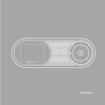
WINNER Single Channel Fixed Cellular GSM Gateway User Manual Version 4.8 CONTENTS 1. OVERVIEW .......................................................................................................................... 3 .1.1 Packing List ................................................................................................................ 3 1.2. Safety Guidelines ....................................................................................................... 4 2. QUICK START GUIDE ............................................................................................................ 5 2.1. General User Information ......................................................................................... 5 3. INSTALLATION STAGES AND PROCEDURES ........................................................................... 7 3.1. Stage 1 - Identifying Potential Sources of Interference ............................................ 7 3.2. Stage 2 - Assessing the Subscriber Site ..................................................................... 7 3.3. Stage 3 - installing the System................................................................................... 8 3.4. Stage 4 - Programming .............................................................................................. 8 4. GENERAL TECHNICAL INFORMATION ................................................................................. 15 4.1. Telephone Line Characteristics ............................................................................... 15 4.2. Enviromental characteristics ................................................................................... 16 4.3. Labels ....................................................................................................................... 16 Winner Single Channel Fixed Cellular GSM Gateway User Manual www.eurotech-communication.com 2 1. OVERVIEW This user’s manual will help you install your WINNER GSM gateway unit in the best possible manner, and provide you with the basic guidelines for handling any problems that might arise. In general, the WINNER GSM single gateway provide a flexible and cost efficient connection between your telephone system and the GSM mobile networks. In essence the device acts as a router that is programmed to choose the Least Cost Route when you make a call from your PSTN line to a cellular phone. The GSM gateway connects to a trunk line and bypasses the telephone company thus significantly reducing overhead costs of telephone calls. Connect to your PBX or landline phone or even to a specific phone extension (special order), and you will save money on all calls by bypassing the telephone network and obtaining direct access to the GSM networks. The embedded Wavecom Module and SIM card act as 'Smart' user Id cards that encrypt voice and data transmissions and store data about the specific user and personal phone settings. Together they make the GSM gateway a cell phone in itself. The WINNER gateways are therefore an essential tool for cutting overhead costs of telephone bills, as they allow direct access to the GSM networks and cuts costs of airtime and interconnections. The WINNER GSM gateways are intended for middle to large enterprises but can be installed on regular phone lines in your home or home office. There are certain features that may be relevant to the product you have selected and some that are not. At any rate all are discussed in the following manual. The WINNER GSM unit, when used with the appropriate telephone equipment (antenna, adapter, SIM cards, telephone PSTN line or PBX) will function as an ordinary landline and support the following features: Cost-saving routing of incoming calls 'Follow Me' call forwarder to your personal mobile GSM and PSTN interconnection via internal LCR Caller ID – Optional. Fax, Data FXS interface Polarity Reverse Outstanding voice performance and echo cancellation 1.1. PACKING LIST When you receive your WINNER device please inspect the package to verify that all the following items have been included: 1) One WINNER GSM single channel gateway unit. 2) 12V Power Supply Adapter. 3) Antenna. 4) Mounting bracket, screws and wall plugs. Winner Single Channel Fixed Cellular GSM Gateway User Manual www.eurotech-communication.com 3 1.2. SAFETY GUIDELINES For the safe and efficient operation of your WINNER gateway unit, please observe the following guidelines: Please read the installation instructions and safety guidelines in this user's manual carefully before installing the unit. Do not handle the equipment before disconnecting it from the electrical outlet Do not use any cleaning agents or detergents on the exterior or interior surfaces. If you intend to clean the device, disconnect it first from the electrical outlet and use a damp cloth only. Do not position the unit in a damp place; do not expose it to water. Do not expose to extreme temperatures: optimal operating temperatures are -5° C to + 50°C. Position equipment in a stable environment; any sudden fall or sharp movement may damage the device. Do not cover or stick any foreign objects over device openings or ventilation holes. Do not operate your WINNER device when any person is within 0.02m of the antenna. A person or object within 0.02 m of the antenna could impair call quality and may cause the phone to operate at a higher power level than necessary. Warning: Potentially Explosive Atmospheres. Do not operate the WINNER near blasting caps, or in a blasting area. Avoid the possibility of triggering an explosion Do not operate a WINNER transmitter in a hazardous atmosphere: an explosion or fire may result. The telephone interface is not designed for outdoor application: The RJ-11 cable must not be run to an outdoor telephone; this minimizes equipment exposure to coupling or direct lightning surges. Winner Single Channel Fixed Cellular GSM Gateway User Manual www.eurotech-communication.com 4 2. QUICK START GUIDE ALWAYS POWER-DOWN THE WINNER UNIT BEFORE INSERTING SIM CARDS 1) Check package contents. 2) Insert Sim card. 3) Connect the antenna. 4) Connect the unit to an analog telephone. 5) Connect the power supply and wait 30 secs. 6) LCD displays: [Voice: Provider name…….Antenna reception bargraph]. 7) Check antenna reception. If reception is poor, disconnect the power and change the antenna location. Repower the system and wait 30 secs. 8) Program the device according to your needs by setting the parameters in the programming menu. 9) Place an outgoing call – dialled number is displayed. 10) Place an incoming call to the unit – incoming number is displayed. 11) Disconnect the analog telephone and reconnect the unit to your PBX line. 2.1. GENERAL USER INFORMATION 2.1.1. PLACEMENT OF THE DEVICE The WINNER GSM gateway unit is designed for installation on a vertical surface but may be mounted on a wall. If you wish to mount the device on a wall follow these steps: 1) Remove the metallic strip used for hanging the unit on the wall by sliding it out from the back of the WINNER unit 2) Hold the metallic strip on the wall and mark the location of the screws with a pencil. 3) Drill holes through the markings, screw down the strip 4) Place the unit onto the wall by sliding the metallic strip back into the groove. 2.1.2. INTERFERENCE TO MEDICAL AND PERSONAL ELECTRONIC DEVICES Most electronic equipment is shielded from RF energy. Nevertheless, RF energy from the WINNER transmitter may affect inadequately shielded electronic equipment. We therefore advise you to consult the manufacturer(s) of your medical and personal electronic device(s), (for example a pacemaker or hearing aid) to determine if they are adequately shielded from external RF energy. Do not install a WINNER gateway unit in a health care facility, if regulations posted in the area restrict the use of cellular phones. Hospitals and health care facilities may be using equipment that is sensitive to external RF energy. Winner Single Channel Fixed Cellular GSM Gateway User Manual www.eurotech-communication.com 5 2.1.3. ANTENNA CONSIDERATIONS Use only the supplied or approved antenna. An unauthorized antenna, modifications or attachments could affect call quality. Winner Single Channel Fixed Cellular GSM Gateway User Manual www.eurotech-communication.com 6 3. INSTALLATION STAGES AND PROCEDURES The installation procedure consists of the following steps: STAGE 1: Identifying potential sources of interference STAGE 2: Assessing the subscriber site STAGE 3: Installing the system STAGE 4: Programming STAGE 5: Testing In/Out calls 3.1. STAGE 1 - IDENTIFYING POTENTIAL SOURCES OF INTERFERENCE The electronic circuitry of some telephones may be insufficiently shielded to operate properly with the WINNER gateway units. When making or receiving a phone call, if your hear a “humming” sound or noise in the earpiece of the telephone connected to the WINNER, or if any other party hears the hum or noise, move the telephone away from the WINNER. If moving it farther away has no effect, try using a different telephone. The WINNER is a two-way radio and as such, some occasional interference is unavoidable. For best results, choose an electrical outlet away from obstructions. Do not place the WINNER near items which may increase static, such as: Electrical appliances Lamps Microwaves TVs Refrigerator Vacuum cleaner Fax Machines 4 Feet (1.2 meters) Light dimmers Motors 3.2. STAGE 2 - ASSESSING THE SUBSCRIBER SITE The WINNER GSM gateway must be installed indoors: Basement installation is not recommended, in some cases it can be accomplished by installing an external antenna. Install in an environment where the temperatures may not exceed the specified operating range (see safety guidelines above). Make sure there is sufficient air circulation. Installation in higher locations is preferred i.e. near windows or outer walls. Winner Single Channel Fixed Cellular GSM Gateway User Manual www.eurotech-communication.com 7 3.3. STAGE 3 - INSTALLING THE SYSTEM ALWAYS POWER-DOWN The WINNER UNIT BEFORE INSERTING SIM CARDS! 1) Inspect the package, you should see: a unit gateway, an antenna, an adapter mounting screws and an RJ11 cable. Note: The WINNER unit comes without the SIM card(s)! 2) Connect the antenna at a distance greater than 1 meter from the unit. Location of the antenna is important in order to obtain best performance, thus once you turn the power on, make sure you have good reception and clear conversation with the unit *. 3) Insert the SIM card in the designated slot (on the right side panel) adjacent to the antenna connection you will see a thin metallic black colored drawer. Use a small pointed object such as the point of a ballpoint pen into the little hole on the right side of that drawer/slot to open the drawer, then insert the SIM face-up into the drawer and close it firmly. 4) Connect an ordinary analog telephone line with the RJ-11 to the socket on left side panel of the gateway unit. 5) On the left side panel you will find the POWER socket. Connect the adapter (provided with unit) to the mains outlet and then to the socket on the unit. Note: The power input is 90 –260 VAC and the output is 12 VDC 1.2 Amp 6) Wait 30 seconds for the unit to startup. Testing When you see the operator/ provider name on the LCD try to make an outgoing call, you should see the number dialed. Make a call to the unit from a remote telephone, cellular or landline, the caller ID should appear on the LCD. Notes 1. Antenna reception: After Sim insertion, antenna connection and power-up, the LCD will display antenna reception power in the form of a small BarGraph. 2. Make sure you have as much reception power as possible, by moving the antenna to different locations. 3.4. STAGE 4 - PROGRAMMING 1) To enter programming mode, pick up the handset of the landline phone and press the star key 3 times "* * *". 2) LCD will indicate "Programming Mode" ( it is now in programming mode). 3) (After 1 second the LCD will display the first parameter: "1. AnsSuperVision "). 4) In order to scroll through the "Programming Options" 'parameter menu' press "#". 5) To enter any sub menu press "*". Winner Single Channel Fixed Cellular GSM Gateway User Manual www.eurotech-communication.com 8 3.4.1. PARAMETER MENU 1. Answer Supervision (AnsSuperVision) - Off Hook Signal type This parameter allows the user to specify the type of signal sent to the PBX when the phone handset is lifted off the cradle. This signal is PBX specific so check your PBX documentation and pay attention to the notes at the bottom. 1) Press "*" to reach the sub menu options. The LCD will display "# - Choose / * - Save". 2) After 1 second the LCD will display "Battery Reversal" (first item in the Sub Menu), To scroll between options in the sub menu press "#", to choose an option press "*". 3) Available signal types (Sub Menu Items): Battery Reversal. (Polarity reverse)* Disable Double Line Reverse Break Line * Polarity reverse timing (Pulse Duration can be programmed using menu parameter 2) “Answer Supervision Timer”. Notes: 1. The “Off Hook Signal” is determined by your type of PBX. 2. If you are using a CDR (Call Detail Record) unit, use “Double Line Reverse” as your preferred option. 2. Answer Supervision Timer Modify “Off Hook Signal” Pulse Duration: This parameter is in multiplications of 100ms (milliseconds). 1) (See your PBX documentation for the correct value). 2) Press "*" to reach the sub menu. The LCD will display "# - Change / * - Exit". 3) After 1 second the LCD will display: "100msX" (100ms times 1). 4) User can change the multiplication value by pressing "#". 5) LCD will display (for about 1sec): "0-9 –Edit / * - Exit". 6) Choose a new multiplication factor by pressing 00 – 09 (2 digit number). 7) Press "*" to accept new value and exit. Winner Single Channel Fixed Cellular GSM Gateway User Manual www.eurotech-communication.com 9 3. Minimum Digits Minimum number of digits to be dialed This parameter allows the user to specify the minimum number of digits to be dialed for any valid outgoing call. 1) Press "*" to reach the sub menu. The LCD will indicate "# - Change / * - Exit". 2) After about a second the LCD display will change to: "Min: 07". 3) Press "#" in order to modify this value. 4) The LCD show "0- 9 Edit / * - Exit" (for 1 sec) and then "Min: (02-10) ". 5) Choose a number between 02 to 10 (2 digit number) or press "*" to exit. Note: When you have finished dialing, the call will go out after the “Inter Digit Timer” delay (menu parameter No. 5) but only if the number of digits dialed is between “Minimum Digits” and “Maximum Digits”. If “Minimum Digits” is less than 02, no call will go out. 4. Maximum Digits Maximum number of digits to be dialed This parameter allows the user to specify the maximum number of digits to be dialed for any valid outgoing call. 1) Press "*" to reach the sub menu. The LCD will indicate "# - Change / * - Exit". 2) After about a second the LCD display will change to: "Max: 10 ". 3) Press "#" in order to modify this value. 4) The LCD show "0- 9 Edit / * - Exit" (for 1 sec) and then "Max: (08-20)". 5) Enter a number between 08 to 20 (2 digit number) or press "*" to exit. Note: When the “Maximum Digits” number is reached during dialing, the call will go out immediately, regardless of any superfluous dialing. 5. Inter Digit Timer The interval between the end of your dialing sequence and the moment the call goes out. This parameter is in multiplications of 50ms (milliseconds). 1) Press "*" to reach the sub menu. The LCD will indicate: "# - Change / * - Exit”. 2) After about a second the LCD display will change to: "50msX200". Winner Single Channel Fixed Cellular GSM Gateway User Manual www.eurotech-communication.com 10 3) Press "#" in order to modify this value. 4) The LCD show "0- 9 Edit / * - Exit" (for 1 sec) and then "50msX (001-200)". 5) Enter a number between 001 to 200 (3 digit number) or press "*" to exit. Note: When you have finished dialing, the call will go out after the “Inter Digit timer” delay (menu parameter No. 5) but only if the number of digits dialed is between “Minimum Digits” and “Maximum Digits”. * If “Minimum Digits” is less than 02, no call will go out. * If “Maximum Digits” is reached during the dialing sequence the call will go out immediately, regardless of any superfluous dialing. 6. Ignore First Digit This parameter allows you to ignore the first dialing digit: 1) Press "*" to reach the sub menu, the LCD will indicate "# - Change / * - Exit". 2) After 1 second the LCD will display: "Digit: Disable". 3) Pressing "#" until LCD shows the digit that you need to ignore. 4) press "*" to choose and exit. 5) Available options 1. Disable: Don’t ignore any digits. 2. 0 to 9: Set the specific digit to be ignored (at the start of the dialed number). 3. Any: Any first dialed digit will be ignored. 7. Software Version Indicates the firmware version. 8. Data Mode: Data mode on / Data mode off This parameter allows the user to transmit digital data over the GSM. An 8pin serial data cable are needed for this means. This mode is optional and is included only in units that have been specifically ordered for this purpose. Must be off when being used for 'Voice' only! Winner Single Channel Fixed Cellular GSM Gateway User Manual www.eurotech-communication.com 11 9. Pre Digit Dialing Allows you to transmit a prefix using an ordinary phone: This parameter allows you to attach a series of digits (i.e. 050) to every number dialed. - i.e. your Cellphone prefix number. Every time you dial a number this prefix will be added automatically. * This attribute can save valuable dialing time. 1) Press "*" to reach the sub menu, the LCD will indicate "# - Change / * - Exit". 2) After a short delay the LCD displays: "String: ". 3) Press "#" and write your prefix – i.e. “050” then press "*" until the 4) LCD display returns to "9. Pre_Dialing". 10. CID: (Setup Caller ID) Caller I.D option This parameter is Optional, and can be obtained by special order only. If this option is active (ON) and your PBX Supports this service, the caller ID will be sent to the target extension, (Caller I.D. will always appear on your LCD. -- With or without this option). 11. PIN Number 1) Allows the gateway to automatically insert PIN number when there is a SIM with a PIN code demand. 2) Press "*" to reach the sub menu, the LCD will indicate "# - Change / * - Exit". 3) After a short delay the LCD displays: "PIN: 1111". Press "*" to accept and exist. 4) Press '#' to change the current PIN Number. 5) The LCD shows "0- 9 Edit / * - Exit" (for 1 sec) and then "NEW PIN:" . 6) Key in the new PIN number (max 8 digits) using the telephone keypad. 7) Press '*' to accept the new PIN number and exit to the parameter menu. 12. CLIR Mode: (CLIR – Clear Caller ID) This parameter allows you to send the call with or without ID display. 1) Press "*" to reach the sub menu, the LCD will indicate "# - Change / * - Exit". 2) Scroll through the Sub Menu options using "#". 3) Press "*" to accept the option in the display and exit to the parameter menu. Available options: 1. By Network: - According to cellular network 2. Invocation: – Inactives ID display 3. Suppression: - ID will be displayed Winner Single Channel Fixed Cellular GSM Gateway User Manual www.eurotech-communication.com 12 13. Voice Gain: Volume of Caller or Receiver Voice * 1) Press " " to reach the sub menu, the LCD will indicate "# - Change / * - Exit". After a second you see LongPress * to edit. # 2) Scroll through the Sub Menu options using " ". * 3) Press " " for 3 secs to change, the LCD shows "0- 9 Edit / * - Exit" (for 1 sec) and then "RX: (000255)". 4) Enter a number between 001 to 255 (3 digit number) or press "*" to exit. 5) Options: Rx gain – Incoming voice Volume Control Tx gain - Outgoing voice Volume Control 14. Dial Tone Gain: Volume of Dial Tone 1) Press "*" to reach the sub menu, the LCD will indicate LongPress * to edit. 2) Press "*" for 3 secs to change, the LCD shows "0- 9 Edit / * - Exit" (for 1 sec) and then "DT: (1200)". 3) Enter a number between 00 to 12 (2 digit number) or press "*" to exit. 15. Lock: SIM specific lock-code See your dealer for details. Use this option carefully. 16. CID Mode: PBX Caller ID compatibility with the gateway Define as determined in the user manual of your PBX or phone. 17. Caller restrict To Block Incoming or outgoing Calls 1) Press "*" to for the sub menu options. The LCD will display: "# - Choose / * - Save". 2) After 1 second the LCD will display "Disable" (first item in the Sub Menu), To scroll between options in the sub menu press "#", 3) To choose the displayed option press "*". Available options Disable: - No restrictions. Incall restrict: Don't allow incoming calls Outcall restrict: - Don't allow outgoing calls. 18. Start Ring: Start up Ring Options: Disable / Enable. When “Enabled” The unit sends a ring tone to your PBX on power up. The ring tone signals to the PBX that the unit is back on-line (after power failure or power up). Winner Single Channel Fixed Cellular GSM Gateway User Manual www.eurotech-communication.com 13 19. Boot Loader: Optional remote programming through comport Enables the user to reprogram (upgrade software) the unit, using a local PC. Boot Loader Mode is only available with units that include “Data mode”. This parameter is Optional, and can be obtained by special order only. For trained personal only! Contact your dealer for details. Winner Single Channel Fixed Cellular GSM Gateway User Manual www.eurotech-communication.com 14 4. GENERAL TECHNICAL INFORMATION Electrical Power supply: 12 VDC +/- 5% 1,2 A 720 mA average in GSM 900 at Tx power max 2W 920 mA average in GSM/GRPS 900 at Tx power max 2W 100 mA in idle mode Physical Absolute maximum dimension: 165 x 127 x 30 mm Weight: 600 g Casing: Complete shielding-stainless steel Mounting: 4 screw holes Operating temperature range: -5°C to + 55°C Optimal storage temperature: -35°C to +85°C Analog Telephone/Analog PBX interface Tip/Ring Voltage: –48V Line current: 25ma Ringing Voltage: 140 Vpp Load: 3REN Crest Factor: 1.25 Frequency: 20 Hz Cadency: 2s/4s Answer supervision - Reverse polarity DTMF compliancy Dial Tone: 400 Hz Busy Tone: 400 Hz, cadency 500ms/500ms GSM Circuit Data Features Data circuit asynchronous, transparent and non transparent up to 14,400 b/s Automatic fax group 3 (Class 1 & 2) Alternate speech and fax MNP2, V.42bis 4.1. TELEPHONE LINE CHARACTERISTICS 4.1.1. DC CHARACTERISTICS Ringing Voltage: -70 V DC typical On hook voltage: -58 V DC typical Off hook Voltage: -24 V DC typical Off hook Loop current: 27mA @ 600 Ohm programming resistive Winner Single Channel Fixed Cellular GSM Gateway User Manual www.eurotech-communication.com 15 Input Impedance: 480 Ohms to 720 Ohms, 600 ohm typical 4.1.2. DTMF DIALING Detection level: -25dBm to +3dBm On time: 50msec. Off time: 12 characters Ringing Signal Feeding type: Balanced signal Distortion: Less than 5% Ring drive capability 3 type A Minimum ring Voltage: 40 Vrms – crest factor 1.2 Frequency: 20 Hz 4.1.3. NORMAL DIALING TONE Frequency: 400Hz Level: 2dB Cadence: continuous 4.1.4. CONGESTION / BUSY TONE Frequency: 400Hz Level: 2dB Cadence: 500ms 20% signal 500ms 20% pause 4.2. ENVIROMENTAL CHARACTERISTICS The WINNER complies to the following requirements: Temperature - we claim -5° to 70° (Israeli Standard Institute Approval is in process). Humidity - 5% to 95% Safety - Testing at Israeli Standard Institute Approval is in process Transportation - Transport conditions are according to EuroTech Standards. Storage Condition - Storage conditions are according to class 1.1, ETS 300 019 –1-1 (-20°C +80°C), 25°C to +65°C 4.3. LABELS Each WINNER is labeled as follows: Product ID: located on the side of the box. The label contains product model number, Serial number, Date and code (identified as WWYY), hardware and software version. Winner Single Channel Fixed Cellular GSM Gateway User Manual www.eurotech-communication.com 16 WWYY: (1’st two digits identify the chronological week in the year, 2nd two digits identify the year). For Example: Logo, Model No, Serial No, Rev. Hardware X / Software Y: 0X/0Y, Date: Month/Year Winner Single Channel Fixed Cellular GSM Gateway User Manual www.eurotech-communication.com 17