1
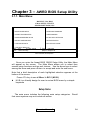
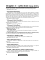
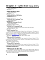
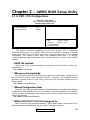
Chapter 3 – AWRD BIOS Setup Utility 3.1. Introduction This manual discusses Award's Setup program built into the ROM BIOS. The Setup program allows users to modify the basic system configuration. This special information is then stored in battery back-up RAM so that it retains the Setup information when the power is turned off. The Award Basic Input / Output System (BIOS) support for detailed fine-tuning of the chipset controlling the entire system. The rest of this manual is intended to guide you through the process of configuring your system using Setup. Starting Setup The Award BIOS is immediately activated when you first power on the computer. The BIOS reads the system information contained in the CMOS and begins the process of checking out the system and configuring it. When it finishes, the BIOS will seek an operating system on one of the disks and then launch and turn control over to the operating system. While the BIOS is in control, the Setup program can be activated by one of two ways: 1. By pressing <Del> immediately after switching the system on, or 2. By pressing the <Del> key when the following message appears briefly at the bottom of the screen during the POST (Power On Self Test). Press <DEL> to enter SETUP. If the message disappears before you respond and you still wish to enter Setup, restart the system to try again by turning it OFF then ON or pressing the "RESET" button on the system case. You may also restart by simultaneously pressing <Ctrl>, <Alt>, and <Delete> keys. If you do not press the keys at the correct time and the system does not boot, an error message will be displayed and you will again be asked to... PRESS <F1> TO CONTINUE, <DEL> TO ENTER SETUP 15 User’s Manual Chapter 3 – AWRD BIOS Setup Utility 3.1.1. Main Menu ROM PCI / ISA BIOS CMOS SETUP UTILITY AWARD SOFTWARE, INC. STANDARD CMOS SETUP INTEGRATED PERIPHERALS BIOS FEATURES SETUP SUPERVISOR PASSWORD CHIPSET FEATURES SETUP USER PASSWORD POWER MANAGEMENT SETUP IDE HDD AUTO DETECTION PNP//PCI CONFIGURATION SAVE & EXIT SETUP LOAD BIOS DEFAULTS EXIT WITHOUT SAVING LOAD SETUP DEFAULTS Esc : Quit F5 : Menu In BIOS F10 : Save & Exit setup áâàß : Select Item (Shift)F2 : Change Color Virus Protection, Boot Sequence…. Once you enter the Award BIOS CMOS Setup Utility, the Main Menu will appear on the screen. The Main Menu allows you to select from several setup functions and two exit choices. Use the arrow keys to select among the items and press <Enter> to accept and enter the sub-menu. Note that a brief description of each highlighted selection appears at the bottom of the screen. Press <F5> key to see all Menu In BIOS (M.I.B.) l M.I.B. is a friendly design for user to review BIOS menu by a simple keystroke Setup Items The main menu includes the following main setup categories. Recall that some systems may not include all entries. User’s Manual 16 Chapter 3 – AWRD BIOS Setup Utility 3.1.2. Standard CMOS Setup ROM PCI / ISA BIOS STANDARD CMOS SETUP AWARD SOFTWARE, INC. Date (mm: dd: yy) Time (hh: mm: ss) : : Wed, May, 03, 1999 9 : 25 : 5 HARD DISK Primary Master Primary Slave Secondary Master Secondary Slave TYPE : Auto : Auto : Auto : Auto Drive A Drive B : 1.44M, 3.5in. : None Video Halt On : EGA/VGA : All Errors Ecs F1 SIZE 0 0 0 0 : Quit : Help CYLS 0 0 0 0 HEAD 0 0 0 0 áâàß : Select Item (Shift)F2 : Change Color PRECOMP 0 0 0 0 LANDZ 0 0 0 0 SECTOR 0 0 0 0 MODE Auto Auto Auto Auto Base Memory : 640K Extended Memory : 261120K Other Memory : 384K ___________________________ Total Memory : 262144K PU/PD/+/- : Modify The items in Standard CMOS Setup Menu are divided into 10 categories. Each category includes no, one or more than one setup items. Use the arrow keys to highlight the item and then use the <PgUp> or <PgDn> keys to select the value you want in each item. ¡¯DAT E The date format is <day>, <month>, <date>, <year>. Press <F3> to show the calendar. day date month year The day, from Sun to Sat, determined by the BIOS and is display-only The date, from 1 to 31 (or the maximum allowed in the month) The month, Jan through Dec. The year, from 1994 through 2079 ¡¯T IME The time format is <hour> <minute> <second>. The time is calculated based on the 24-hour military-time clock. For example, 1 p.m. is 13:00:00. ¡¯DAYLIGHT SAVING The category adds one hour to the clock when daylight-saving time begins. also subtracts one hour when standard time returns. Enabled Disabled 17 Enable daylight-saving Disable daylight-saving User’s Manual It Chapter 3 – AWRD BIOS Setup Utility ¡¯Primary Master/ Primary Slave/ Secondary Master/ Secondary Slave The categories identify the types of 2 channels that have been installed in the computer. There are 45 predefined types and 4 user definable types are for Enhanced IDE BIOS. Type 1 to Type 45 are predefined. Type user is user-definable. Press PgUp or PgDn to select a numbered hard disk type or type the number and press <Enter>. Note that the specifications of your drive must match with the drive table. The hard disk will not work properly if you enter improper information for this category. If your hard disk drive type is not matched or listed, you can use Type ”User” to define your own drive type manually. If you select Type ”User”, you will need to know the information listed below. Enter the information directly from the keyboard and press <Enter>. This information should be included in the documentation from your hard disk vendor or the system manufacturer. If the controller of HDD interface is ESDI, the selection shall be ”Type 1”. If the controller of HDD interface is SCSI, the selection shall be ”None”. If you select Type ”Auto”, BIOS will Auto -Detect the HDD & CD-ROM Drive at the POST stage and showing the IDE for HDD & CD-ROM Drive. T YPE CYLS. HEADS PRECOMP LANDZONE SECT ORS MODE drive type number of cylinders number of heads write precom landing zone number of sectors mode type If a hard disk has not been installed select NONE and press <Enter>. ¡¯Drive A T ype/ Drive B T ype The category identifies the types of floppy disk drive A or drive B that have been installed in the computer. The choice : None, 360K (5.25in) , 1.2M (5.25in) , 720K (3.5in), 1.44M (3.5in), 2.88M (3.5in) . ¡¯VIDEO The category selects the type of video adapter used for the primary system monitor. Although secondary monitors are supported, you do not have to select the type in Setup. The choice: EGA/VGA, CGA 40, CGA 80, MONO. ¡¯HALT ON The category determines whether the computer will stop if an error is detected during power up. The choice: No errors, All errors; All, But Keyboard; All, But Diskette; All, But Disk/Key . ¡¯MEMORY The category is display-only which is determined by POST (Power On Self Test) of the BIOS. User’s Manual 18 Chapter 3 – AWRD BIOS Setup Utility Base Memory The POST will determine the amount of base (or conventional) memory installed in the system. The value of the base memory is typically 512K for systems with 512K memory installed on the motherboard, or 640K for systems with 640K or more memory installed on the motherboard. Extended Memory The BIOS determines how much extended memory is present during the POST. This is the amount of memory located above 1MB in the CPU's memory address map. Other Memory This refers to the memory located in the 640K to 1024K address space. This is memory that can be used for different applications. DOS uses this area to load device drivers in an effort to keep as much base memory free for application programs. The BIOS is the most frequent user of this RAM area since this is where it shadows RAM 3.1.3. BIOS Features Setup ROM PCI / ISA BIOS BIOS FEATURES SETUP AWARD SOFTWARE, INC. ChipAwayVirus on Guard CPU Internal Cache External cache Quick Power On Self Test Boot Sequence Swap Floppy Drive Boot Up Floppy Seek Boot Up Numlock Status Boot Up System Speed Gete A20 Option Typematic Rate Setting Typematic Rate (Chars/Sec) Typematic Delay (Msec) Security Option IDE Second Channel Control PS/2 mouse function control PCI/VGA Palette Snoop OS Select For DRAM > 64MB Report No FDD For WIN 95 19 : Enabled : Enabled : Enabled : Enabled : A, C, SCSI : Disabled : Enabled : On : High : Normal : Disabled :6 : 256 : Setup : Disabled : Disabled : Disabled : Non-OS2 : No Video BIOS C8000-CBFFF CC000-CFFFF D0000-D3FFF D4000-D7FFF D8000-DBFFF DC000-DFFFF Shadow Shadow Shadow Shadow Shadow Shadow Shadow : Enabled : Disabled : Disabled : Disabled : Disabled : Disabled : Disabled Esc : Quit áâàß : Select Item F1 : Help PU/PD/+/- : Modify F5 : Old Values (Shift)F2 : Color F6 : Load BIOS Defaults F7 : Load Setup Defaults User’s Manual Chapter 3 – AWRD BIOS Setup Utility This section allows you to configure your system for basic operation. You have the opportunity to select the system default speed, boot-up sequence, keyboard operation, shadowing and security. ¡¯ChipAwayVirus on Guard When this item is Trend ChipAwayVirus (TCAV) on Guard. Boot Viruses pose the most severe threat because they can move from a floppy diskette to your hard drive in less then a second. And it all happens during the loading of the boot sector. Provides a virus-free boot and operating system, experience peace of mind though hardware-base virus protection, detects known and unknown boot viruses with rule-based technology, receive immediate protection! Already installed on this board!. The Choice: Enabled, Disabled . ¡¯CPU Internal Cache/ External Cache These two categories speeds up memory access. However, it depends on CPU /Chipset design. The default value is enable. The Choice: Enabled, Disabled . ¡¯Quick Power On Self Test This category speeds up Power On Self Test (POST) after you power up the computer. If it is set to Enable, BIOS will shorten or skip some check items during POST. The Choice: Enabled, Disabled . ¡¯ Boot Sequence This category determines which driver to search first for the disk operating system (i.e.,DOS). Default value is A,C. The Choice: A,C,SCSI ; C,A,SCSI ; C,CDROM,A ; CDROM,C,A ; D,A,SCSI ; SCSI,A,C ; SCSI,C,A ; C only ; LS/ZIP,C . ¡¯Swap Floppy Driver This item allows you to determine whether enable the swap floppy driver or not. The Choice: Enabled, Disabled . ¡¯Boot Up Floppy Seek During POST , BIOS will determine if the floppy disk driver installed is 40 or 80 tracks. 360K type is 40 tracks while 720K, 1.2M and 1.44M are all 80 tracks. The Choice: Enabled, Disabled . ¡¯Boot Up Numlock Status This allows you to determine the default status of the numeric keypad. By default, the system boots up with NumLock on . The Choice: On , Off . ¡¯Gate A20 Option This entry allows you to select how the gate A20 is handled. The gate A20 is a device used to address memory above 1 Mbytes. Initially, the gate A20 was handled User’s Manual 20 Chapter 3 – AWRD BIOS Setup Utility via a pin on the keyboard. Today, while keyboards still provide this support, it is more common, and much faster, for the system chipset to provide support for gate A20. The Choice: Normal, Fast. ¡¯T ypematic Rate Setting This determines if the typematic rate is to be used. When disabled, con-tinually holding down a key on your keyboard will generate only one instance. In other words, the BIOS will only report that the key is down. When the typematic rate is enabled, the BIOS will report as before, but it will then wait a moment, and, if the key is still down, it will begin the report that the key has been depressed repeatedly. For example, you would use such a feature to accelerate cursor movements with the arrow keys. The Choice: Enabled, Disabled . ¡¯T ypematic Rate (Chars/Sec) When the typematic rate is enabled, this selection allows you select the rate at which the keys are accelerated. The Choice: 6, 8, 10, 12, 15, 20, 24, 30 . ¡¯T ypematic Delay (Msec) When the typematic rate is enabled, this selection allows you to select the delay between when the key was depressed and when the acceleration begins . The Choice: 250, 500, 750, 1000 . ¡¯Security Option This category allows you to limit access to the system and setup, or just to setup . The Choice: System, Setup . Note: To disable security, select PASSWORD SETTING at Main Menu and then you will be asked to enter password. Do not type anything and just press <Enter>, it will disable security. Once the security is disabled, the system will boot and you can enter setup freely . ¡¯OS Select for DRAM > 64 MB This item allows you to access the memory that over 64MB in OS/2 . The Choice: Non-OS2 , OS2 . ¡¯PCI / VGA Palette Snoop It determines whether the MPEG ISA / VESA VGA Cards can work with PCI / VGA or not . The Choice: Enabled, Disabled . ¡¯Video BIOS Shadow Determines whether video BIOS will be copied to RAM. However, it is optional depending on chipset design. Video Shadow will increase the video speed . The Choice: Enabled, Disabled . ¡¯C8000 – CBFFF Shadow / DC000 – DFFFF Shadow These categories determine whether option ROMs will be copied to RAM. An example of such option ROM would be support of on-board SCSI. The Choice: Enabled, Disabled . 21 User’s Manual Chapter 3 – AWRD BIOS Setup Utility 3.1.4. Chipset Features Setup ROM PCI / ISA BIOS CHIPSET FEATURES SETUP AWARD SOFTWARE, INC. Auto Configuration EDO DRAM Speed Selection EDO CASx# MA Wait State EDO RASx# Wait State SDRAM RAS-to-CAS Delay SDRAM RAS Precharge Time SDRAM CAS lantecy Time SDRAM Precharge Control DRAM Data Integrity Mode System BIOS Cacheable Video BIOS Chacheable Video RAM Chaceable 8 Bit I/O Recovery Time 16 Bit I/O Recovery Time Memory Hole At 15M-16M Passive Release Delayed Transaction AGP Aperture size (MB) : Enabled : 60 ns :2 :2 :3 :3 :3 : Disabled : Non-ECC : Enabled : Enabled : Disabled :1 :1 : Disabled : Enabled : Disabled : 64 Spread Spectrum CPU Host Clock CPU Warning Temperature Current System Temp. Current CPU1 Temperature Current CPUFAN1 Speed. Current CPUFAN2 Speed Current CPUFAN3 Speed IN0(V) +3.3V +12V -5V : 2.78V : 3.37V : 12.46V : 5.04V IN1(V) +5V -12V : Disabled : Disabled : Disabled : 23¢ J73¢ K : 30¢ J86¢ K : 5627 RPM : 5753 RPM : 0 RPM : 2.49V : 4.99V : -12.54V Esc : Quit áâàß : Select Item F1 : Help PU/PD/+/- : Modify F5 : Old Values (Shift)F2 : Color F6 : Load BIOS Defaults F7 : Load Setup Defaults This section allows you to configure the system based on the specific features of the installed chipset. This chipset manages bus speeds and access to system memory resources, such as DRAM and the external cache. It also coordinates communications between the conventional ISA bus and the PCI bus. It must be stated that these items should never need to be altered. The default settings have been chosen because they provide the best operating conditions for your system. The only time you might consider making any changes would be if you discovered that data was being lost while using your system. DRAM SETTING The first chipset settings deal with CPU access to dynamic random access memory (DRAM). The default timings have been carefully chosen and should only be altered if data is being lost. Such a scenario might well occur if your system had mixed speed DRAM chips installed. So that greater delays may be required to preserve the integrity of the data held in the slower memory chips. ¡¯Auto Configuration This item allows you selects pre-determined optimal values for DRAM, cache, timing according to CPU type & system clock. The Choice: Enabled, Disabled. ¡¯EDO DRAM Speed Selection This value in this speed to fit your DRAM‘ s timming. The Choice: 50ns, 60ns. User’s Manual 22 Chapter 3 – AWRD BIOS Setup Utility ¡¯EDO CASx# MA Wait State Use the default setting. The Choice: 1 , 2. ¡¯EDO RASx# Wait State Use the default setting. The Choice: 1 , 2 . ¡¯SDRAM RAS-to-CAS Delay Use the default setting. The Choice: 2 , 3 . ¡¯SDRAM CAS Precharge Time Use the default setting. The Choice: 2 , 3. ¡¯SDRAM Precharge Control Use the default setting. The Choice: Enabled, Disabled . ¡¯DRAM DATA Integrity Mode Memory parity check function in your memory module with parity check. The Choice: Non-ECC , ECC. ¡¯AGP Aperture Size Select the size of the Accelerated Graphics Port (AGP) aperture. The aperture is a portion of the PCI memory address range dedicated for graphics memory address space. Host cycles that hit the aperture range are forwarded to the AGP without any translation. See www.agpforum.org for AGP information. The Choice: 4MB, 8MB, 16MB, 32MB, 64MB, 128MB, 256MB. ¡¯System BIOS Cacheable Selecting Enabled allows caching of the system BIOS ROM at F0000h-FFFFFh, resulting in better system performance. However, if any program writes to this memory area, a system error may result. The Choice: Enabled, Disabled. ¡¯Video BIOS Cacheable Selecting Enabled allows caching of the system BIOS ROM at C0000h-F7FFFh, resulting in better system performance. However, if any program writes to this memory area, a system error may result. The Choice: Enabled, Disabled. ¡¯Memory Hole at 15M – 16M You can reserve this area of system memory for ISA adapter ROM. When this area is reserved, it cannot be cached. The user information of peripherals that need to use this area of system memory usually discusses their memory requirements. The Choice: Enabled, Disabled. 23 User’s Manual Chapter 3 – AWRD BIOS Setup Utility ¡¯CPU Host Clock 66MHz The Choice: Disable, 66, 75, 83MHz. 100MHz The Choice: Disabled, 100 ~ 150MHz. 133MHZ The Choice: 133 ~ 150MHz. Jumper setting 133MHz, must be setup 133 ~ 150MHz ¡¯CPU Warning Current CPU /Sys Temp. FAN Speed Set the desire temperature that you want to get the warning beep when CPU temperature are higher than it. (option function) All these information are showing the current situation of the CPU (option function). 3.1.5. Power Management Setup ROM PCI / ISA BIOS POWER MANAGEMENT SETUP AWARD SOFTWARE, INC. Power Management PM Control by APM Video Off Method Video Off After MODEM Use IRQ Doze Mode Standby Mode Suspend Mode HDD Power Down Suspend Mode Option Throttle Duty Cycle VGA Active Monitor Soft-Off by PWR-BTTN CPUFAN Off In Suspend Resume by Ring Resume by Alarm : User Define : Yes : DPMS : Suspend :3 : Disabled : Disabled : 8 Min : Disabled : Power On Suspend : 62.5% : Disabled : Instant-Off : Enabled : Enabled : Disabled IRQ 8 Break Suspend : Disabled ** Reload Global Timer Eve IRQ [3-7, 9-15], NMI Primary IDE 0 Primary IDE 1 Secondary IDE 0 Secondary IDE 1 Floppy Disk Serial Port Parallel Port nts ** : Disabled : Disabled : Disabled : Disabled : Disabled : Disabled : Enabled : Disabled Esc : Quit áâàß : Select Item F1 : Help PU/PD/+/- : Modify F5 : Old Values (Shift)F2 : Color F6 : Load BIOS Defaults F7 : Load Setup Defaults User’s Manual 24 Chapter 3 – AWRD BIOS Setup Utility The Power Management Setup allows you to configure you system to most effectively save energy while operating in a manner consistent with your own style of computer use. ¡¯Power Management Its category allows you to select the type (or degree) of power saving and is directly related to the following modes : 1. Doze Mode 2. Suspend Mode 3. HDD Power Down There are for Power Management, three of which have fixed mode settings. Disable Min. Power Saving Max. Power Saving User Defined No power management. Disables all four modes Minimum power management. Do ze Mode = 1 hr. Stand b y Mod e = 1 hr., Suspend Mode = 1 hr., and HDD Power Down = 15 min. Ma ximum power management -- ONLY AVAIL ABL E FOR SL CPU’ S. Doze Mod e = 1 min., Standb y Mode = 1 min., Suspend Mode = 1 min., and HDD Power Down = 1 min. Allows you t o set each mode indi vidually. W hen not disabled, each of the ran ges are from 1 min. to 1 hr. e xce pt for HDD Power Dow n which ranges from 1 min. to 15 min. and disable. ¡¯PM Control APM When enabled, an Advanced Power Management device will be activated to enhance the Max. Power Saving mode and stop the CPU internal clock. If Advance Power Management (APM) is installed on your system, selecting Yes gives better power savings. If the Max. Power Saving is not enabled, this will be preset to No. ¡¯Video Off After When enabled, this feature allows the VGA adapter to operate in a power saving mode. Always On Suspend --> Off Susp,Stby --> Off All Modes --> Off Monitor will remain on during power saving modes. Monitor blanked when the systems enters the Suspend mode. Monitor blanked when the system enters either Suspend or Standby modes. Monitor blanked when the system enters any power saving mode. ¡¯Video Off Method This determines the manner in which the monitor is blanked. V/H SYNC+Blank Blank Screen 25 T his selection will cause the system to turn off the vertical and horizontal s ynchronization ports and write blanks to the video buffer. T his option only writes blanks to the video buffer. User’s Manual Chapter 3 – AWRD BIOS Setup Utility DPMS Select this option if your monitor supports the Display Power Ma nagement Sign aling (DPMS) standard of the Video Electronics Standards to select video power management values. ¡¯MODEM Use IRQ Name the interrupt request (IRQ) line assigned to the modem (if any) on your system. Activity of the selected IRQ always awakens the system. The choice: 3, 4, 5, 7, 9, 10, 11, NA. ¡¯Soft-Off by PWR-BTTN This item allows you to set the off function of power button by software control. The choice: Delay 4 Sec, Instant Off. PM Timers The following four modes are Green PC power saving functions which are only user configurable when User Defined Power Management has been selected. See above for available selections. ¡¯Standby Mode W hen enabled and after the s et time of s ystem inactivity, the fixed disk drive and the video would be shut off while all other devices still operate at full speed. ¡¯Doze Mode When enabled and after the set time of system inactivity, the CPU clock will run at slower speed while all other devices still operate at full speed. ¡¯Suspend Mode When enabled and after the set time of system inactivity, all devices except the CPU will be shut off. PM Events You may disable activity monitoring of some common I/O events and interrupt requests so they do not wake up the system. The default wake-up event is keyboard activity. ¡¯HDD Ports Activity When set to On (default), any event occurring at a HDD (serial) port will awaken a system which has been powered down. ¡¯COM Ports Activity When set to On (default) , any event occurring at hard or floppy drive port will awaken a system which has been powered down. User’s Manual 26 Chapter 3 – AWRD BIOS Setup Utility ¡¯Power ON by Ring W hen you select Enabled, a signal from ring returns the system to Full On state. The choice: Enabled, Disabled. ¡¯Resume by Alarm When you select Enabled, the following fields appear. They let you set the alarm that returns the system to Full On state. The choice: Enabled, Disabled. ¡¯LPT Ports Activity When set to On (default), any event occurring at a LPT (printer) port will awaken a system which has been powered down. The following is a list of IRQ’ s, Interrupt Re Quests, which can be exempted much as the COM ports and LPT ports above can. When an I/O device wants to gain the attention of the operating system, it signals this by causing an IRQ to occur. When the operating system is ready to respond to the request, it interrupts itself and performs the service. As above, the choices are On and Off. Off is the default. When set On, activity will neither prevent the system from going into a power management mode nor awaken it. IRQ3 (COM2) IRQ4 (COM1) IRQ5 (LPT2) IRQ6 (Floppy Disk) IRQ7 (LPT1) IRQ8 (RTC Alarm) IRQ9 IRQ2 Redir) 27 IRQ10 (Reserved) IRQ11 (Reserved) IRQ12 (PS/2 Mouse) IRQ13 (Coprocessor) IRQ14 (Reserved) IRQ15 (Reserved) User’s Manual Chapter 3 – AWRD BIOS Setup Utility 3.1.6. PNP / PCI Configuration ROM PCI / ISA BIOS PNP / PCI CONFIGURATION AWARD SOFTWARE, INC. PNP OS Installed Resources Controlled by Reset Configuration Data : No : Auto : Disabled Esc : Quit áâàß : Select Item F1 : Help PU/PD/+/- : Modify F5 : Old Values (Shift)F2 : Color F6 : Load BIOS Defaults F7 : Load Setup Defaults This section describes configuring the PCI bus system. PCI, or Personal Computer Interconnect, is a system which allows I/O devices to operate at speeds nearing the speed the CPU itself uses when communicating with its own special components. This section covers some very technical items and it is strongly recommended that only experienced users should make any changes to the default settings. ¡¯PNP OS Installed Select Yes if the system operating environment is Plug-and-Play aware (e.g. Windows 95) The choice: Yes and No. ¡¯Resource Controlled By The Award Plug and Play BIOS has the capacity to automatically configure all of the boot and Plug and Play compatible devices. However, this capability means absolutely nothing unless you are using a Plug and Play operating system such as Windows95. The choice: Auto and Manual. ¡¯Reset Configuration Data Normally, you leave this field Disabled. Select Enabled to reset Extended System Configuration Data (ESCD) when you exit Setup if you have installed a new add-on and the system reconfiguration has caused such a serious conflict that the operating system can not boot. The choice: Enabled and Disabled . ¡¯IRQ 3/4/5/7/9/10/11/12/14/15 Assigned To When resources are controlled manually, assign each system interrupt as one of the following types, depending on the type of device using the interrupt: User’s Manual 28 Chapter 3 – AWRD BIOS Setup Utility Legacy ISA Devices compliant with the original PC AT bus specification, requiring a specific interrupt (such as IRQ4 for serial port 1). PCI/ISA PnP Devices compliant with the Plug and Play standard, whether designed for PCI or ISA bus architecture. The choice: Legacy ISA and PCI/ISA PnP. ¡¯DMA 0/1/3/5/6/7 Assigned To When resources are controlled manually, assign each system DMA channel as one of the following types, depending on the type of device using the interrupt: Legacy ISA Devices compliant with the original PC AT bus specification, requiring a specific interrupt ( such as IRQ4 for serial port 1). PCI/ISA PnP Devices compliant with the Plug and Play standard, whether designed for PCI or ISA bus architecture. The choice: Legacy ISA and PCI/ISA PnP. ¡¯PCI IRQ Activated By This sets the method by which the PCI bus recognizes that an IRQ service is being requested by a device. Under all circumstances, you should retain the default configuration unless advised otherwise by your system manufacturer. The choice: Level (default) and Edge. ¡¯PCI IDE IRQ Map To This allows you to configure your system to the type of IDE disk controller in use. By default, Setup assumes that your controller is an ISA (Industry Standard Architecture) device rather than a PCI controller. The more apparent difference is the type of slot being used. If you have equipped your system with a PCI controller, changing this allows you to specify which slot has the controller and which PCI interrupt (A, B,C or D) is associated with the connected hard drives. Remember that this setting refers to the hard disk drive itself, rather than individual partitions. Since each IDE controller supports two separate hard drives, you can select the INT# for each. Again, you will note that the primary has a lower interrupt than the secondary as described in ”S lot x Using INT#” above. Selecting ”P CI Auto” allo ws the system to automatically determine how your IDE disk system is configured. 29 User’s Manual Chapter 3 – AWRD BIOS Setup Utility 3.1.7. Load BIOS Setup ROM PCI / ISA BIOS POWER MANAGEMENT SETUP AWARD SOFTWARE, INC. POWER MANAGEMENT SETUP IDE HDD AUTO DETECTION PNP/PCI CONFIGURATION SAVE & EXIT SETUP LOAD BIOS DEFA SAVING LOAD BIOS SETUP (Y/N)?Y LOAD SETUP DEF Esc : Quit F10 : Save & Exit setup áâàß : Select Item (Shift)F2 : Change Color This Load BIOS Defaults option allows you to load the troubleshooting default values permanently stored in the BIOS ROM . These default setting are non-optimal and disable all high performance features. To load these default setting, highlight Load BIOS Defaults on the main screen and then press the <Enter> key. The system displays a confirmation massage on the screen. Press the <Y> key and then the <Enter> key to confirm. Press the <N> key and then the <Enter> key to abort. This feature does not affect the fields on the Standard CMOS Setup screen. 3.1.8. Load BIOS Defaults ROM PCI / ISA BIOS POWER MANAGEMENT SETUP AWARD SOFTWARE, INC. POWER MANAGEMENT SETUP IDE HDD AUTO DETECTION PNP/PCI CONFIGURATION SAVE & EXIT SETUP LOAD BIOS DEFA LOAD SETUP DEF Esc : Quit F10 : Save & Exit setup LOAD SETUP DEFAULTS (Y/N)?Y SAVING áâàß : Select Item (Shift)F2 : Change Color This Load Setup Defaults option allows you to load the default values to the system configuration fields. These default values are the optimized configuration settings for the system. To load these default values, highlight Load Setup Defaults on the main screen and then press the <Enter> key. The system displays a confirmation message on the screen. Press the <Y> key and then the <Enter> key to confirm. Press the <N> key and then the <Enter> key to abort. This feature does not affect the fields on the Standard CMOS Setup screen. User’s Manual 30 Chapter 3 – AWRD BIOS Setup Utility 3.1.9. Integrated Peripherals ROM PCI / ISA BIOS INTEGRATED PERIPHERALS AWARD SOFTWARE, INC. IDE HDD Block Mode IDE Primary Master PIO IDE Primary Slave PIO IDE Secondary Master PIO IDE Secondary Slave PIO IDE Primary Master UDMA IDE Primary Slave UMA IDE Secondary Master UDMA IDE Secondary Slave UDMA On-Chip Primary PCI IDE On-Chip Secondary PCI IDE USB Keyboard Support Init Display First POWER ON Function : Enabled : Auto : Auto : Auto : Auto : Auto : Auto : Auto : Auto : Enabled : Enabled : Disabled : PCI Slot : BUTTON ONLY Onboard FDC Controller Onboard Serial Port 1 Onboard Serial Port 2 UART Mode Select Onboard Parallel Port Parallel Port Mode : Enabled : 3F8/IRQ4 : 2F8/IRQ3 : Normal : 378/IRQ7 : SPP Esc : Quit áâàß : Select Item F1 : Help PU/PD/+/- : Modify F5 : Old Values (Shift)F2 : Color F6 : Load BIOS Defaults F7 : Load Setup Defaults ¡¯On-Chip First Channel This chipset contains a internal PCI IDE interface with support for two IDE channels. Select Enabled to activate the first and/or second IDE interface. Select Disabled to deactivate this interface, if you install a first and/or second add-in IDE interface IDE interface. The choice: Enabled, Disabled. ¡¯IDE Prefetch Mode Enable prefetching for IDE drive interfaces that support its faster drive accesses. If you are getting disk drive errors, change the setting to omit the drive interface where the errors occur. Depending on the configuration of your IDE subsystem, this field may not appear, and it does not appear when the Internal PCI/IDE field, above, is Disabled. The choice: Enabled, Disabled. ¡¯ IDE HDD Block Mode This item allows your hard disk controller to use the fast block mode to transfer data to and from your hard disk drive (HDD). Select Enabled only if your hard drives support block mode. The choice: Enabled, Disabled. ¡¯ IDE Primary/Secondary Master/Slave PIO The four IDE PIO (Programmed Input/ Output) fields let you set a PIO mode (0-4) for each of the four IDE devices that the onboard IDE interface supports. Modes 31 User’s Manual Chapter 3 – AWRD BIOS Setup Utility 0 through 4 provide successively increased performance. In Auto mode, the system automatically determines the best mode for each device. ¡¯ IDE Primary/Secondary Master/Slave UDMA Ultra DMA/33 implementation is possible only if your IDE hard drive supports it and the operating environment includes a DMA driver (Windows 95 OSR2 or a third-party IDE bus master driver). If your hard drive and your system software both support Ultra DMA/33, select Auto to enable BIOS support. The Choice: Auto, Disabled. ¡¯ Onboard FDC Controller This should be enabled if your system has a floppy disk drive (FDC) installed on the system board and you wish to use it. Even when so equipped, if you add a higher performance controller, you will need to disable this feature. The Choice: Enabled, Disabled ¡¯ Onboard Serial Port 1/ Port 2 This item allows you to determine access onboard serial port 1/port 2 controller with I/O address. The choice: 3F8/IRQ4, 2E8/IRQ3, 3E8/IRQ4, 2F8/IRQ3, Disabled. ¡¯ UART 2 Mode This item allows you to determine whic h Infr a R ed ( IR) function of onboard I/O chip. The choice: Standard, ASKIR, HPSIR. ¡¯ IR Function Duplex This item allows you to s elect the IR function when you s elect the UART 2 Mode is ASKIR The Choice: Half, Full. ¡¯ RxD, TxD Active This item allows you to determine the active of RxD, TxD. The Choice: ”Hi, Hi”, ”Lo, Lo”, ”Lo, Hi”, ”Hi, Lo”. ¡¯Onboard Parallel Port This item allows you to determine access onboard parallel port controller with which I/O address. The choice: 378/IRQ7, 278/IRQ5, 3BC/IRQ7, Disabled. ¡¯Onboard Parallel Mode Select an operating mode for the onboard parallel (printer) port. Normal EPP (Extended Parallel Port) ECP (Extended Capabilities Port) ECP+EPP PC AT parallel port Bi-directional port Fast, buffered port Fast, buffered, bi-directional port. Select Normal unless you are certain your hardware and software both support EPP or ECP mode. The choice: SPP, ECP/EPP, ECP, EPP/SPP. User’s Manual 32 Chapter 3 – AWRD BIOS Setup Utility ¡¯USB Keyboard Support Select Enabled if your s ys tem c ontains a U nivers al Serial Bus (USB) c ontr oller and you have a USB keyboard. The choice: Enabled, Disabled. ¡¯Power ON Function This item allows you to s elect which way to power on your c omputer. Pass wor d keyboard wake-up your system, press your password key and <Enter> key. The choice: Button O nly, H ot Key, Pass wor d, Keyboard 98, Mous e Move, Mous e Click. Password Hot Key Setup your Password, and enter it (five words at most). Then confirm your Password Select : <Ctrl> + <F1> … <F12> NOTE : If you forget the password you set before , you can read page- 10 Clear CMOS Password Data (JB1) to reset your CMOS Data. 33 User’s Manual Chapter 3 – AWRD BIOS Setup Utility 3.1.10. Supervisor / User Password Setting You can set either supervisor or user password, or both of then. The differences between are: user password to : just can only enter but do not have the right change the options of the setup menus. When you select this function, the following message will appear at the center of the screen to assist you in creating a password. ENTER PASSWORD: Type the password, up to eight characters in length, and press <Enter>. The password typed now will clear any previously entered password from CMOS memory. You will be asked to confirm the password. Type the password again and press <Enter>. You may also press <Esc> to abort the selection and not enter a password. To disable a password, just press <Enter> when you are prompted to enter the password. A message will confirm the password will be disabled. Once the password is disabled, the system will boot and you can enter Setup freely. PASSWORD DISABLED. When a password has been enabled, you will be prompted to enter it every time you try to enter Setup. This prevents an unauthorized person from changing any part of your system configuration. Additionally, when a password is enabled, you can also require the BIOS to request a password every time your system is rebooted. This would prevent unauthorized use of your computer. You determine when the password is required within the BIOS Features Setup Menu and its Security option . If the Security option is set to ”System”, the password will be required both at boot and at entry to Setup. If set to “Setup”, prompting only occurs when trying to enter Setup. User’s Manual 34 Chapter 3 – AWRD BIOS Setup Utility 3.1.11. IDE HDD Auto Detection ROM PCI / ISA BIOS CMOS SETUP UTILITY AWARD SOFTWARE, INC. HARD DISKS Primary Master : TYPE SIZE CYLS HEAD RECOMP LANDZ SECTOR MODE Select Primary Master Option (N=Skip) :N OPTION SIZE CYLS HEAD RECOMP LANDZ SECTOR MODE 2(Y) 853 827 32 0 1653 63 LBA 1 853 1654 16 65535 1653 63 Normal 3 853 827 32 65535 1653 63 Large Note: Some OS (Like SCO-UNIX) must be “NORMAL” for installation ESC: Skip The Setting on the screen are for reference only. Your version may not be identical to this one. Us e this option to detect the par ameters for the hard dis k drives installed in your system. Thes e par ameters will then be automatic ally enter ed into the “ Standar d CMOS Setup” . The IDE HD D Auto D etection scr een displays the f ollowing c ategories of information: Size, Cylinders, Heard, Precomp, LandZone, Sectors, and Mode 3.1.12. Save and Exit Setup ROM PCI / ISA BIOS POWER MANAGEMENT SETUP AWARD SOFTWARE, INC. STANDARD CMOS SETUP INTEGRATED PERIPHERALS BIOS FEATURES SETUP SUPERVISOR PASSWORD CHIPSET FEATURES SETUP USER PASSWORD POWER MANAGEMENT SETUP IDE HDD AUTO DETECTION PNP/PCI CONFIGURATION SAVE & EXIT SETUP LOAD BIOS DEFA LOAD SETUP DEF Esc : Quit F10 : Save & Exit setup SAVE to CMOS and EXIT (Y/N)?Y SAVING áâàß : Select Item (Shift)F2 : Change Color Select this option to save into the CMOS memory all modifications you specify during the current session. To save the configuration changes, highlight the Save & Exit Setup option on the main screen and then press the <Enter> key. 35 User’s Manual Chapter 3 – AWRD BIOS Setup Utility 3.2. Upgrade BIOS Utility The upgrade process requires two files , the new BIOS file (XXXX. bin) and the upgrade utility (awdflash. exe). Both files can be downloaded from your vendor’s Web site. RUNNING THE UPGRADE PROGRAM: 1. Boot system from the bootable floppy diskette you created. Booting from the diskette bypasses loading drivers from the CONFIG.SYS and AUTOEXE. BAT files on the hard drive, eliminating the possibility of loading a program (a.g., a memory manager) that conflicts with the AWARD flash utility. NOTE : The Award flash utility cannot run when EMM386 or QEMM are loaded. If you try, an error message appears. 2. At the DOS command line, type AWDFLASH and press <Enter>. 3. The cursor should be opposite “FILE NAME to PROGRAM” 4. Type the name of the new BIOS file (for example, newbios. bin), and press <Enter>. 5. At the bottom of the menu, this prompt appears: Do you Want to Save BIOS (Y/N)? 6. If you DO NOT wish to save the old BIOS, type <N> and press <Enter>. Then move to step 8. If you DO wish to save the old BIOS, respond <Y>, and press <Enter>. 7. In the “File Name to Save” field, type a file name for the old BIOS (for example, oldbios. bin), and press <Enter>. Your old BIOS is saved in a file as named, in the default drive and directory (in this example, on the A drive). 8. Then the program prompts you Do You Want to Update? (Y/N) 9. If you DO NOT wish to update the BIOS, type <N> and press <Enter>. The program exits to the command line. Skip the remainder of this section and go directly to the next section. If you DO wish to update the BIOS, respond <Y> and press <Enter>. When the updating is finished, the following message appears: Programming Flash Memory – 3FF00(for 2MB) OK Please Power off or Reset System 10. Restart you system. You BIOS should be successfully update. User’s Manual 36