1
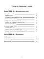
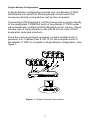
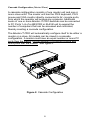
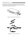
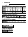
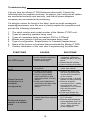
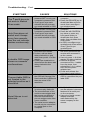
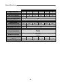
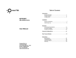
Limited Warranty IN NO EVENT SHALL THE DIRECT VENDOR'S LIABILITY FOR DIRECT OR INDIRECT, SPECIAL, INCIDENTAL OR CONSEQUENTIAL DAMAGES, LOSS OF PROFIT, LOSS OF BUSINESS, OR FINANCIAL LOSS WHICH MAY BE CAUSED BY THE USE OF THE PRODUCT EXCEED THE PRICE PAID FOR THE PRODUCT. The direct vendor makes no warranty or representation, expressed or implied with respect to the contents or use of this documentation, and especially disclaims its quality, performance, merchantability, or fitness for any particular purpose. The direct vendor also reserves the right to revise or update the product or documentation without obligation to notify any user of such revisions or updates. For further information, please contact your direct vendor. All brand names and registered trademarks are the property of their respective owners. 1 Table of Contents CHAPTER 1 – INTRODUCTION Overview 1 Features 1 Configurations 2 CHAPTER 2 – INSTALLATION Installation Overview 3 Components 4 Single Master Configuration 5 Cascade Configuration (Master/Slave) 6 Dual Console Configuration 7 External Power Supply 7 Multi-Media Module (optional) 7 Rack-Mount Kit (optional) 8 CHAPTER 3 – O PERATION Front Panel Buttons & LEDs 9 Reset 8 Port Selection 9 Buzzers & Beeps 9 2 Table of Contents – cont. CHAPTER 3 – O PERATION (CONT .) Hot-Key Commands 9 To Select a Port 9 To Initiate or Deactivate Auto-Scan 10 To Initiate Manual Scan 10 To Adjust the Scan Rate Interval 10 To Adjust the Keyboard Typematic Rate 11 To initiate Audio-Stick 11 On-Screen-Display (OSD) 12 To Label a Port (F1) 12 To Select Ports for Auto-Scan (F2) 14 To Lock / Unlock a Port with a Password (F3) 14 CHAPTER 4 – A PPENDIX Part Descriptions 15 Troubleshooting 16~18 Specifications 19 3 1 INTRODUCTION Overview ConnectPRO is proud to announce the Master-IT PRO professional line of KVM switches. With the use of one keyboard, one monitor, and one mouse, multiple computer systems can be accessed and controlled. Designed for both industrial and office use, the Master-IT PRO functions independently of the operating system and does not require any additional interface cards or software. Installation is simply a matter of connecting cables. Front panel buttons, hot-key commands, and OnScreen-Display features provide easy operation and computer selection. The Master-IT PRO is available in 2, 4, 8, & 16 port models, as well as Dual-Console configurations providing connectivity for over 128 systems from a single console. All models support both PS/2 and AT/Serial mice and keyboards and are easily installed in standard 19” server racks with the exception of the PR-12, which is not rack mountable. The On-Screen-Display (OSD) is an optional facility and is available on all models with four or more ports. The OSD includes features for automatic scanning of select systems, secure port authentication, visual port identification, and cascade systems monitoring. Firmware upgrades are standard, and for those special projects, the Master-IT PRO can be configured with specially designed firmware to accommodate the most unique industrial applications. The Master-IT PRO is the best cost-effective and space saving solution for industrial and office applications. Features • • • • • • • • • • • • Manage over 128 systems with one or two consoles. All hot-swappable ports. System selection by front panel buttons, or hotkey commands. Supports 1920 x 1440 video resolution. Supports 200 MHz bandwidth. Auto-Scan facility. 19" rack-mountable (except PR-12). Two-Tier cascadable. Buzzer sound for switching confirmation. Supports PS/2 & AT/Serial mice & keyboards. Individual port buttons and LEDs. Project specific firmware available. 4 Configurations The Master-IT PRO can be set up as a Single Master or cascaded in a Master/Slave configuration. A single master involves only one Master-IT PRO KVM switch, and has the keyboard, monitor and mouse directly connected to its’ console ports. A cascaded configuration involves “daisy-chaining” a slave Master-IT PRO KVM switch to the master unit. The KVM switch which has the keyboard, monitor and mouse directly connected to it is considered the master. All others are considered as slaves. The master must have an equal number or more PC ports than the slave. Do not attempt to configure a slave with more PC ports than the master. In a cascaded configuration, the PC ports of the master are used to “daisy-chain” to the console ports of the slave. Only PC ports 1 through 8 can be used to “daisy-chain” to the console ports of the slave. 5 2 INSTALLATION Installation Overview Installation is simply a matter of connecting cables to their appropriate ports on each Master-IT PRO and each computer. Prior to beginning the installation procedures, verify that all Master-IT PRO KVM switches are powered OFF. Once the configuration is completed, add consoles, cables and computers in the following order: 1. If necessary, install the optional rack-mount kit to each Master-IT PRO KVM switch and mount it in the rack. Then mount the cable support bar to the back of the rack. 2. Connect the 9V DC 500mA power adapter to each Master-IT PRO KVM switch. 3. Connect the keyboard, monitor, and mouse directly to the console ports of the master. 4. Connect one end of each Premium 3-in-1 cable to an available PC port on each Master-IT PRO KVM switch. 5. Connect the other end of each Premium 3-in-1 cable to each computer. Then power ON each computer. Computers that are already powered ON can be connected at any time. Components Bellow is a list of components that make up a complete Master-IT PRO configuration. • • • • • Master-IT PRO KVM switch. ConnectPRO Premium 3-in-1 KVM Cables. A power adapter with a rating of 9V DC 500mA and polarity of positive-on-center. Master-IT PRO Rack-Mount Kit. (optional) Master-IT Multi-Media module. (optional) 6 Single Master Configuration A Single Master configuration involves only one Master-IT PRO KVM switch into which the PS/2 keyboard, monitor and PS/2 mouse are directly connected as well as the computers. Connecting a PS/2 keyboard, a PS/2 mouse and a monitor directly to the designated CONSOLE ports of any Master-IT PRO model will automatically configure that KVM switch as the master. (There are two sets of console ports on the PR-28 for two sets of PS/2 keyboards, mice and monitors). Once the console ports are occupied, connect multiple sets of premium 3-in-1 cables (Part #: PS-1P) to the computer ports of the Master-IT PRO to complete a Single Master configuration. See figure 1. Figure 1. Single Console Connection 7 Cascade Configuration (Master/Slave) A cascade configuration consists of one master unit and one or more slave units. The master unit has the PS/2 keyboard, PS/2 mouse and VGA monitor directly connected to its’ console ports, from which the operator will access any computer. Additional levels of one or more Master-IT PRO switches can be connected to PC Ports 1~8 of a MASTER or SLAVE unit to expand the number of computers that can be accessed and controlled, thereby creating a cascade configuration. The Master-IT PRO will automatically configure itself to be either a master or a slave. All models can be mixed in a cascade configuration. A master must have an equal number or more PC ports than the slaves. Do not attempt to configure a slave with more ports that the master. See figure 2. Figure 2. Cascade Configuration 8 Dual-Console Configuration The advanced Dual-Console Master-IT PRO, has the same functionality and features as the single console version. However, it also enables individual access and control from either of two separate consoles at different locations. Currently available in an 8-port configuration, ConnectPRO can specially manufacture the Dual-Console version in 2, 4 & 16 ports to accommodate your project requirements. The Dual-Console Master-IT PRO is the IT Managers’ solution for Bi-locational command and control. External Power Supply In the event that additional power is required, a 9V DC 500mA power adapter is supplied with a polarity of positive-on-center. In a Single Master configuration, an external power supply may not be required unless power starvation is evident. In a cascade configuration, the power adapter should be connected to the master and each slave to facilitate the On-Screen-Display (OSD) functions. Multi-Media Module (optional) The Master-IT Multi-Media Module, MAV-108, can be connected to any 4 through 8 port Master-IT PRO KVM switch, through it’s Mini-DIN-8 link port. It allows the operator to simultaneously perform audio tasks from either the currently selected computer or from a computer that is on a different port entirely. The MAV-108 is a true multi-tasking facility. (Figure 4.) 9 Rack-Mount Kit (optional) An optional Rack-Mount Kit is available for Master-IT PRO models with 4 through 16 ports. It fits perfectly in standard 19” server racks. The kit includes side mount brackets, and a cable support bar, which mounts on the back of the rack enclosure. (Figure 5.) Mas terIT P R -1 8 PRO Figure 3. Rack-Mount Kit Side Brackets Figure 4. Rear Cable Support Bar. 10 3 OPERATION Front Panel Buttons Each Master-IT PRO model has front panel buttons, which can be used to initiate different functions manually. They can be used to select ports, initiate the Auto-Scan function, and reset keyboard and mouse connectivity. To select a port to access a connected computer, simply press the corresponding front panel button once. Figure 5. Front Panel Button & LED To initiate keyboard and mouse reset, simultaneously press and release the #1 & #2 front panel buttons for 5 seconds. Each model with more than two ports will have its’ own pair of front panel buttons designated for activating Auto-Scan manually. Simultaneously pressing and releasing these two buttons will initiate the auto-scan function. To deactivate auto-scan, press and release the left CTRL keyboard key twice or press the reset button combination. Front Panel LED Indicators The LED indicators above the front panel buttons illuminate green and red to verify that there is a powered on computer occupying that port, and to show that a particular port has been activated. Green indicates that a port is occupied with a powered ON computer. Red indicates that port has been activated. 11 Buzzers and Beeps Whenever a command or event is initiated, either a buzzer or beep will sound to indicate a successful or failed command. A built-in buzzer generates a high-pitch beep for correct hot-key command; otherwise, one low-pitch beep for error Hot-Key Commands TO SELECT A PORT: In a single master configuration, press and release the left CTRL key twice, followed by the keys that represent the number of the port that has the computer. For example, to select a computer that is connected to port 5, press and release the left CTRL key twice, then press the #5 key once. CTRL , CTRL , 5 In a cascade configuration (master/slave), press and release the left CTRL key twice, followed by the number key that represents the port on the master that is being used to daisy-chain, then press the number key that represent the port on the slave that the computer is connected to. For example, to select a computer that is connected to port # 8 of a slave, when port # 1 of the master is used to daisy-chain, press and release the left CTRL key twice, then press and release the #1 key, then press and release the #8 key. CTRL , CTRL , 1 , 8 12 TO INITIATE OR D EACTIVATE AUTO-S CAN: Press and release the left CTRL key twice, followed by the F1 key once. CTRL , CTRL , F1 To deactivate the Auto Scan feature, press and release the left CTRL key twice. When Auto Scan detects any keyboard or mouse activity, it suspends the scanning until activity stops; it then resumes with the next computer in sequence. The length of the Auto Scan interval (Scan Rate) is adjustable. Locked devices will be skipped during the scan. The Auto Scan facility automatically displays either all computers that are powered ON or individually selected computers chosen by the operator, one-by-one at a fixed interval. TO INITIATE MANUAL SCAN: Press and release the left CTRL key twice, followed by the F2 key once. CTRL , CTRL , F2 Manual Scan enables manual back and forth switching between computers that are powered ON. Locked devices cannot be scanned. Press ↑ (up) arrow key or ↓ (down) arrow key to select the previous or the next computer in sequence. To deactivate Manual Scan, press any other key. TO A DJUST THE SCAN RATE I NTERVAL: To adjust the Scan Rate interval, press and release the left CTRL key twice, followed by the F3 key once. CTRL , CTRL , F3 E ntering this key sequence sets the time duration between switching to the next computer. One to four beeps will sound to indicate a scan rate interval of 3, 8, 15 and 30 seconds respectively. 13 TO A DJUST THE K EYBOARD T YPEMATIC RATE: To adjust keyboard typematic rate (characters/sec), press and release the left CTRL key twice, followed by the F4 key once. CTRL , CTRL , F4 Each time this key sequence is entered,1 to 4 beeps will sound corresponding to 10, 15, 20 and 30 characters/sec respectively. This typematic setting will override the typematic settings of the computers’ BIOS and the operating system. TO INITATE AUDIO -S TICK: To initiate or deactivate the Audio-Stick feature, press and release the left CTRL key twice, followed by the F5 key once. CTRL , CTRL , F5 Each time this hot-key sequence in entered, an ON or OFF state is initiated and 1 or 2 beeps will sound corresponding to ON or OFF respectively. This hot-key sequence facilitates the optional MAV-108 multi-media module which would be LINKed to a designated MASTER unit of a Master-IT PRO configuration. When set to ON, audio selection follows computer selection. When set to OFF, audio selection stops following computer selection. This allows the operator to listen to a particular computer's audio signals while operating other computers. 14 On-Screen-Display (OSD) TO INITIATE OSD: Press and release the left CTRL key twice to view the hot-key menu. Press and release the left CTRL key three times to view the KVM MENU. The Hot-Key Menu shows instructions for the various OSD functions. Use this as a guide to become familiar with its’ functions. The KVM Menu shows a list of the computers with corresponding channel addresses, names and status information. TO EXIT OSD: Press and release the ESC key once. TO LABEL A PORT: To edit a name entry of a computer or a Master-IT PRO slave unit. Use the ↑ (up) and ↓ (down) arrow keys to highlight a channel, then press the F1 key followed by an 8 character name entry. Valid characters are A~Z, and 0~9 and the dash character. Lowercase letters are automatically converted to capitals. Press the BACKSPACE key to make changes. All name entries are retained until changed by the operator, even if the unit is completely powered OFF or in storage. 15 Figure 6. On-Screen-Display TO SELECT A COMPUTER FROM WITHIN THE OSD: Use the ↑ (up), ↓ (down), and → (right) arrow keys on the keyboard, to choose the computer, then press the ENTER key to finalize the selection. TRIANGLE MARK (4): A triangle mark (4) to the right of a name indicates the port is cascaded to a Slave; the number at the left of the triangle mark shows the number of ports the Slave has, i.e. 84for PR-18. Pressing the ENTER key brings you one level down and another screen pops up listing the names of the computers on that Slave. The name of the Slave will be shown at the upper right corner of the OSD menu. It is useful when grouping computers and still be able to see the group name. 16 EYE M ARK (N ): An eye mark (N) to the right of a name indicates this computer is selected to be monitored while in Scan mode. In OSD, this mark can be switched on or off by pressing and releasing the F2 key once. TO LOCK A D EVICE WITH A PASSWORD: 1. Scroll to the desired port where the device is connected, then press and release the F3 key once. Only one device can be locked at a time, either a computer or a Master-IT PRO KVM switch that has been configured as a slave. 2. Type in up to four characters for the password, then press and release the ENTER key once to complete the lock. A lock mark ( Ï) will indicate that port is secure. There are two ways to access a locked device: a. Permanently unlock a device from within OSD by pressing and releasing the F3 key once, then enter the password. b. Temporarily unlock a device for access by selecting a locked port and typing in the password when prompted. The device will then automatically return to the LOCKED status when any other port is selected. NOTE: If the password is forgotten or lost, the only way to regain access is to permanently disable the security function by removing all possible power sources from the Master-IT PRO unit that has been configured as the MASTER unit. All computers and slave units as well as the 9V power adapter must be removed from the master unit. 17 4 APPENDIX Part Descriptions Master-IT PRO Models: Model # PR-12 PR-14 PR-18 PR-116 PR-28 PR-216 1 1 1 1 2 2 2 4 8 16 8 16 Max.# of Computers Controllable 4 16 64 128 128 128 Max. # of Cascade Levels 2 2 2 2 2 2 # of Console Ports # of PC Ports ConnectPRO Premium 3-in-1 Cable Models: Part # Length PS-06P Connectors PS/2 (m/m) DB-9 (m/f) 6 ft. PS-10P PS-15P PS-25P PS-50P PS-100P 10 ft. 15 ft. 25 ft. 50 ft. 100 ft. PS/2 (m/m) DB-9 (m/f) PS/2 (m/m) DB-9 (m/f) PS/2 (m/m) DB-9 (m/f) PS/2 (m/m) DB-9 (m/f) PS/2 (m/m) DB-9 (m/f) m/m = male to male connectors m/f = male to female connectors Master-IT PRO Rack-Mount Kit Models: Master-IT PRO Rack-Mount Kit Part # PR-12 PR-14 PR-18 PR-116 PR-28 PR-216 n/a RX-1 RX-2 RX-3 RX-2 RX-3 n/a = not available Master-IT PRO Power Adapter: Part # Rating Polarity AD-0950 9Volt DC 500mA Positive on Center Master-IT Multi-Media Module: Part # # of Ports Type of Ports MAV-108 8 Microphone & Speaker 18 Troubleshooting If at any time the Master-IT PRO behaves abnormally, Consult the following table for possible solutions. As always, first verify that all cables are connected correctly and securely, and that all power adapters necessary are connected and functioning. If a solution cannot be found in the table, send an email message to: [email protected]. Be sure to clearly explain the symptoms and provide the following information: 1. 2. 3. 4. 5. 6. 7. The serial number and model number of the Master-IT PRO unit. Types of operating systems being used. Types of computers being connected: PS/2 or AT/Serial. Brands and models of mouse and keyboard being used. Type of configuration: Single Master or Cascade (master/slave). Name of the person or business that purchased the Master-IT PRO. Contact information of the user who is experiencing the difficulties. SYMPTOMS No OSD screen. Keyboard error on boot. Cannot access computers in a cascade configuration. Keyboard strokes remain in a shifted state. CAUSES SOLUTIONS • No power. • Loose monitor connection. • Monitor is not a multisynchronous type. • After rebooting the computers, press and release the left CTRL key twice • Reconnect the monitor. • Use a multi-sync monitor. • Reconnect the keyboard cable, then reboot. • Loose keyboard connection. • A slave unit has more ports than the master. • A slave unit has been daisy-chained to a port other than ports1~8 of the master. • Power was installed to a slave before the slave was daisy chained to the master. • The computer was in shifted state when was last switched. 19 • Remove the slave that has more ports than the master and reconnect it as the master. • Use only ports 1~8 of the master for daisy-chaining. • Remove all power sources and 3-in-1 cables from the slave, then reinstall the 3-in-1 cables first, and the power adapter last. • Press and release the front panel reset buttons. • Press both SHIFT keys for 5 seconds. • Remove and reinstall all power adapters and 3-in-1 cables. First reinstall the 3-in-1 cables, then the power adapters. Troubleshooting - Cont. SYMPTOMS The ↑ and ↓ keys do not work in Manual Scan mode. Auto Scan does not switch and it beeps every few seconds, also the red indicator flashes continuously. A double OSD image shows on cascade configurations. The port lable OSD is not located in the selected position as it should be. Serial Mouse is not detected. CAUSES SOLUTIONS • Either all computers are powered OFF or only one computer is powered ON. • Scan type is eye mark selected but no ports are eye mark selected in OSD. • Either all computers are powered OFF or only one computer is powered ON. • Scan type is eye mark selected but no ports are eye mark selected in OSD. • Power ON more than one computer. • Press the ESCAPE key to deactivate Manual Scan mode, then reconfigure eye marked ports. • Power ON more than one computer. • Press the left CONTROL key twice or press any front panel button to deactivate Auto Scan mode, then reinitiate Auto Scan mode. • In OSD, reconfigure eye marked ports, then set the Scan Type for eye marked ports. • Remove the slave that has more ports than the master and reconnect it as the master. • Use only ports 1~8 of the master for daisy-chaining. • Remove all power sources and 3-in-1 cables from the slave, then reinstall the 3-in-1 cables first, and the power adapter last. • Press and release the front panel reset buttons. • Use the the F4 function in OSD to reposition the port label OSD. • A slave unit has more ports than the master. • A slave unit has been daisy-chained to a port other than ports1~8 of the master. • Power was installed to a slave before the slave was daisy chained to the master. • The size and position of the OSD will change if its’ fixed resolution is different than the actual VGA resolution. • The serial mouse adapter is not securely fastened. • The manufactuers of the serial mouse adapter and the mouse are different. Different manufactuers pin-out assignments often cause conflicts. • The serial mouse adapter should only be connected to a serial port on the computer. 20 • Verify that the serial mouse adapter is securely fastened to a serial port on the computer. • Use only a serial mouse adapter that was manufactured by the same company as the mouse. Troubleshooting – Cont. SYMPTOMS Cannot switch to computers located on a slave. The switch occassionally and irregularly experiences various malfunctions. CAUSES SOLUTIONS • The cables are not securely fastened. • There is a another slave cascaded to the first slave. • The slave has more ports than the master. • The slave is cascaded from a port other than 1~8 of the master. • Securely reconnect all cables. • Do not cascade a 3rd level slave to a 2nd level slave. Only one slave per port can be cascaded from the master. • Reconfgure the installation so that the master always has an equal number or more ports than the slave. • Cascade a slave only from ports 1~8 of the master. • Verify that the OSD menu on the master shows a triangle mark next to the port that is cascaded. • Connect a 9V DC 500mA power adapter (Part #: AD-0950) to the switch. • Insufficient power being supplied by the connected computers will result in power starvation to the switch. 21 Specifications PR-12 PR-14 PR-18 1 2 1 4 1 8 1 16 2 8 2 16 Max. # of Computers 4 16 64 128 64 128 On-screen display (OSD) Front panel button control N/a RX-2 RX-3 # of Console Ports # of Computer Ports PR-116 PR-28 PR-216 Yes Yes Hot plug-and-play Yes Hot-key control Rack-mount kit Part # N/a Yes Automatic scan interval N/a Yes Programmable scan interval VGA Resolution N/a Yes 1600x1200 RX-1 RX-2 RX-3 Console Connectors DB-15 (f) PS/2 (f) Computer Connectors DB-15 (m) PS/2 (f) Dimensions (L x W x H) (mm / in) 40x124x70 44x220x130 44x436x180 88x436x220 44x436x180 88x436x220 1.6x4.9x2.7 1.7x8.7x5.1 1.7x17.2x7.0 3.5x17.2x8.7 1.7x17.2x7.0 3.5x17.2x8.7 Power Supply 9V DC 500mA (positive on center) 22