1
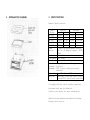
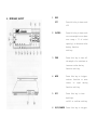
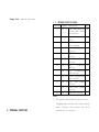
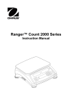
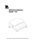
GW SERIES
MULTI-FUNCTION DIGITAL SCALE
OPERATION MANUAL
CONTENTS
1. INSTALLATION INSTRUCTION
2. INSTALLATION DIAGRAM
3. SPECIFICATIONS
PLEASE READ THIS MANUAL VERY CAREFULLY
4. KEYBOARD LAYOUT
BEFORE ATTEMPT TO OPERATE THE SCALE
5. KEYBOARD DESCRIPTION
6. INTERNAL FUNCTIONS
7. OPERATING INSTRUCTION
8. TROUBLE SHOOTING
9. DAILY CARE AND MAINTENANCE
AUGUST 1999 REV 2
10. APPENDIX
Specifications subject to change without prior
notice
1. INSTALLATION INSTRUCTION
1.3.1 This scale is powered by the built-in
rechargeable battery and/ or by a AC
1.1
adapter included.
1.3.2 Chec k and make sure that the voltage of
CHECK AND MAKE SURE THA T THE FOLLOWING
ITEMS ARE INCLUDED.
This operation manual
Scale x 1
Plastic platter x 1
AC adaptor x 1
the AC adaptor supplied matches with the
voltage of the main output. Contact your
dealer if not.
1.3.3 Insert the output plug of AC adaptor
Stainless steel platter cover x 1
(option)
Contact your dealer if any items missed.
1.2
firmly into the DC input jack of scale.
The DC input jack is located at the left
side of scale.
1.3.4 Before first time
PLACING THE PLATTER
use,
charge
the
1.2.1 Place the platter into the scale in
built-in rechargeable battery for at
least 8 hours or until the charging
longitude
or
latitude
direction
preferred. Always place the platter into
indicator turns green.
1.3.5 For safety reasons, do not share the same
the scale gently, no excessive force is
needed. Then place the stainless steel
platter cover (if purchased) onto the
plastic platter.
1.2.2 The stainless steel platter cover can
be fixed permanently to the platter by
putting a double side adhesive tape
between the platter and the stainless
1.3
platter cover.
POWER THE SCALE
mains outlet with other apparatus.
1.4
Retain all packi ng material for future
transportation of scale.
2. INSTALLATION DIAGRAM
3. SPECIFICATIONS
General Specifications
Model
Number
GW-1500
GW-3000
GW-7500
GW-15K
GW-30K
Power
Source
Capacity
Division
Metric Pound* Metric
Pound*
1500g 3.3 1b
0.1g
0.01 oz
3000g 6.6 1b
0.2g
0.02 oz
7500g
16 1b
0.5g
0.05 oz
15000g 33 1b
1g
0.1 oz
30000g 66 1b
2g
0.2 oz
By Built-in Rechargeable Battery
and /or, AC Adaptor output = DC9V/
500mA
Platter
215 x 250mm
Tare Range Full Range
Zero Range Maximum = 2% of Rated Capacity
Auto Piece Weight Enhancement Range:
Minimum = 4 pieces
Maximum = 100% of max. counts previously
achieved
Temp. Range 0 ~ 400C (32 ~ 1040F)
Options:
Backlight, Stainless Steel Platter
Cover,RS232 and Printer Interface
*To comply with the law of certain countries,
the pound unit may be disabled.
Contact your dealer for more information.
Specifications and functions subject to change
without prior notice.
4. KEYBOARD LAYOUT
1
KEYS
OFF
Press this key to turn scale
off.
2
ON/ZERO
Press this key to turn scale
on or set weight to zero (max.
zero range = 2% of rated
capacity) or decrease value
during function
setting.
3
TARE
Press this key to tare off
the weight of a container or
increase value during
function setting.
4
MODE
Press this key to trigger
various function or move
cursor to right
function setting.
5
SET
during
Press this key to turn
backlight
on/off or confirm setting.
6
HI/LO/SAMPLE Press this key to trigger
various function value
setting.
7
stable.
DISPLAY SIGNSZERO STATUS SIGN. When the
à0ß
weigh detected is at true
zero, an arrow will appear
and point at this sign.
8
-
12 HI INDICATOR This sign will on when
weight detected exceeds the
upper weight limit.
13 GO INDICATOR This sign will on when
weight detected falls within
MINUS SIGN. When the weight
detected is below zero, an
the upper and lower limit.
arrow will appear and point
at this sign.
14 LO INDICATOR This sign will on when
weight detected is below the
lower weight limit.
9
TARE STATUS SIGN. When the
tare function is being
employed, an arrow with
15 FUNCTION
INDICATOR
appear and point at this sign
.
10
LOW BATTERY SIGN. When this
sign is on, recharge the
battery or employ the AC
adaptor/AC
immediately.
11
MOTION
INDICATOR
cord
This sign appears when
weight detected is not
The function indicator
displays the function currently being
employed.
16
OTHERS
CHARGE
INDICATOR
RED: Built-in rechargeable
battery is being
recharged.
GREEN: Rechargeable battery
is completely
charged.
17 RS232/PRINTEROutput port for computer or
Output Port
printer interface.
6.1 INTERNAL FUNCTION TABLE
Function Symbol Description
Note
1
Fun - 1 Scale configuration
A
setting and dealer
calibration.
2
Fun – 2 Display
segment
check.
3
Fun – 3 Off set value and span A
value reading.
4
Fun – 4 Auto
power
off
setting.
5
Fun - 5 RS232
baud
rate B
setting.
6
Fun – 6 Auxiliary weight unit A
setting.
10
Fun – 10 RS232
protocol B
setting.
11
Fun – 11 RS232
transmission B
mode setting.
12
Fun – 12 Printer transmission C
mode setting.
20
Fun – 20 RS232 data format B
setting.
21
Fun – 21 Printer data format C
setting.
30
Fun - 30 Beep mode setting.
NOTE:
A
For dealer and authorized person only.
Inappropriate setting will cause system
down. Contact your dealer for more
6. INTERNAL FUNCTIONS
information or service.
B
C
Function when RS232 interface is purchased.
Function when printer interface is
e. Press
TARE
until
the
setting/value appears.
purchased.
f. Press SET to confirm.
h. Repeat step c to step f for other function
6.2 HOW TO ENTER THE REQUIRED FUNCTION MODE
6.2.1 Function 1 to 6
required
setting, or
j. Press HI/LO/SAMPLE to save setting and
a. Turn scale off.
b. Press and hold MODE, then turn scale on.
return to normal operation.
Scale displays Fun-1
c. Press MODE until the required function
6.3 Internal Functions Description
number appears.
d. Press SET
Fun-1 Contact
your
dealer
for
more
information.
e. Press MODE until the required setting/
value appears.
Fun-2 To check all displa y segment works
properly.
f. Press SET to confirm.
h. Repeat step c to f for other function
Fun-3 Contact
setting, or
j. Press HI/LO/SAMPLE to save settings and
return to normal operation.
6.2.2
Function 10 to 30
your
dealer
for
more
information.
Fun-4 To set the Auto Power Off Function.
Two modes are available: (Default =
a. Turn scale on.
4_OFF)
0_OFF = Auto Power Off Function is
b. Press and hold SET until Fun - 10 appears.
c. Utilize MODE, TARE and ON/ZERO to
disabled.
4_OFF = Scale will automatically turned
achieve required function number.
d. Press SET to enter.
off aft er 4 minutes used.
Fun-5 Set RS232 baud
available:
rate:
7
rates
are
300, 600, 1200, 2400, 4800, 9600 and
19200
Fun-6 Contact
your
dealer
for
Under this mode, no data will be
transmitted if weight detected
02 =
is less than 40 d.
Continuos transmission
mode.
Under this mode, data is
continuously
transmitted
more
information.
disregarding weight applied or
detected.
Fun-10Set RS232C protocol. Two modes are
available:
E.7 = even parity, 7 data bit
N.8 = no parity, 8 data bit
Fun-12Set Printer transmission mode. Two
modes are available:
00 =
Fun-11Set RS232C transmission mode. Three
modes are available:
00 =
Key transmission mode. Data is
ON/ZERO is pressed.
Under this mod e, no data will be
transmitted only when
ON/ZERO is pressed.
the
transmitted if weight detected
is less than 2% of rate capacity.
Under this mode, no data will be
transmitted if weight detected
Refer to Appendix A for minimum
weight required.
is less than 2% of rate capacity.
Refer to Appendix 1 for minimum
01 =
Key transmission mode. Data is
transmitted
only
when
the
01 =
Auto transmission mode. Data is
transmitted when detected is
weight required.
Auto transmission mode. Data is
stable.
Under this mode, no data will be
transmitted
when
detected is stable.
transmitted if weight detected
is less than 40 d.
weight
Refer to Appendix A for minimum
weight required.
Beep 1: Alarm when weight detected
falls within the upper and lower
NOTE : Details
of
every
transaction
transmitted will be stored in memory.
limit.
Beep 2: Alarm when weight detected
Press MODE to transmit the total value
accumulated to printer.
exceeds the upper limit or below
the lower limit.
NOTE : The data stored in memory will be erased:
a. when MODE is pressed, or
Beep 3: Alarm when weight detected
exceeds the upper limit.
b. when scale is turned off, or
c. when weight unit is changed.
Beep 4: Alarm when weight detected is
below the low limit.
Fun-20Set RS232 data format. Three formats
are available:
00 = Format 0 (Default)
01 = Format 1
02 = Format 2
Refer to Appendix B for individual
transmission format.
Fun-21Set Printer data format
00 = Format (Default)
01 = Format (Mot available)
Refer to Appendix C for printout format.
Fun-30Set Weight Check Beep Mode
Beep 0: No alarm output, (Default)
7.OPERATING INSTRUCTION
7.1
PLACING THE SCALE
Place this scale on a hard and strong
enough surface where is free from RF
interference, vibration, fire, direct
sunlight and excessive moisture.
When backlight is on, press SET to turn
backlight off.
For best weighing result, always place
this scale on a level surface. This scale
is equipped with a bubble level. If
required, adjust the adjustable feet
underneath the scale to obtain a level
7.4
TARE FUNCTION
7.4.1
To Tare Off the Weight of a Container
Place a container onto platter, then
press TARE to tare off the weight of it.
After the TARE is pressed, the tare sign
POWER ON/OFF THE SCALE
will appear.
To Clear the Weight of a Container from
7.2
condition.
7.2.1To turn scale on, press ON/ZERO.
7.4.2
Memory
7.2.2To turn scale off, press OFF.
Remove the container from the platter
7.3 BACKLIGHT MODE
7.3.1Turn backlight on
then press TARE. The tare sign will go
off indicating no container weight is
a. press SET during normal operation.
b. Backlight is turned on.
resided in memory.
NOTE:
The backlight function is monitored by
a power saving program. Backlight will
ZERO FUNCTION
If Zero Status Sign does not appear when
be automatically turned off after
weight displayed is unchanged for about
scale is unloaded, press ZERO to reset
weight displayed to zero. Refer to
30
seconds.
Backlight
will
automatically be turned on again by
general specification table for maximum
zero range.
pressing any key or when a new weight
is detected.
7.3.2
7.5
Turn backlight off
7.6
PLACING LOAD
Always place a load onto the platter
gently. Sudden shock, excessive force
7.7
or overloading the scale may cause
damage to the weight sensor inside.
obtained. The unit piece weight forms
the foundation of quantity calculation.
It is a good practice to remove all load
from platter when not in used. This would
a. If a container is used, place the
container onto the platter first then
prolong the lifetime of weight sensor.
press TARE to tare off the weight of it.
b. Place a sample size with known quantity
WEIGHING FUNCTION
a. Before weighing, make sure that the Zero
onto the platter. The number of the
sample size must equal to one of the below
Status Sign is on.
b. Press MODE until the required weight
value:
5, 10, 20, 50, 100, 200, 500 or 1000pieces
unit appears.
c. Place subject matter on platter and the
c. Press HI/LO/SAMPLE until 5 PCS
appears.
weight of it is displayed.
For best weighing result, refer to
d. Press TARE until corresponding sample
number appears.
general
specification
table
for
recommended minimum weight to be
e. Press SET to confirm. The unit piece
weight is obtained and scale is now ready
applied.
Hint:
7.8
COUNTING FUNCTION
7.8.1
Turn scale on. Press MODE until the PCS
NOTE:
7.8.2
sign appears. Make sure that the Zero
Status Sign is on.
Sampling
Sampling is the first step of counting
NOTE:
transaction. By means of sampling
process, the unit piece weight is
for counting transaction.
It is usually true that the more the
sample size, the more accurate the
subsequent counting result.
For best counting result, refer to
general
specification
table
for
recommended minimum piece weight.
An error sign will appear if the unit
piece weight is less than the feather
unit weight. Refer to Appendix E for more
7.8.3
information.
place more/remove some subject matter
onto the platter. The new quantity will
Counting Transact ion
be shown on the display.
Put more subject matter or remove part
7.9
of the subject matter, the new piece
value is shown on the display.
7.9.1.2 The Auto Unit Piece Weight Enhancement
Function will update the unit piece
AUTO PIECE WEIGHT ENHANCEMENT FUNCTION
weight if both of the below requirements
are met:
In order to obtain the best counting
result and to avoid sampling error, this
a. The quantity added to platter is more
than 4 pieces of previous maximum counts
scale is equipped wit h Auto Unit Piece
Weight Enhancement function.
This function is resided in memory once
the unit piece is obtained by the
NOTE:
previously attained
transaction.
from
the
same
b. The quantity added to platter is less
than 100% of previous maximum counts
sampling method as described in 7.8.2.
Auto Unit Piece Weight Enhancement
previously attained
transaction.
from
the
same
Function will be terminated if a zero
weight
is
detected
during
the
7.9.1.3 If the above requirements are met, a
new unit piece weight will be displayed
transaction process. It is strongly
piece weight is unknown or individual
on the Unit Weight window and confirmed
by an audio "beep".
piece weight is not standardized.
7.10
7.9.1
How Auto Piece Weight Enhancement
Function Works.
7.9.1.1 After a unit piece weight is obtained
by method as described in 7.8.2 then
WEIGHT CHECK FUNCTION
This scale is equipped with Weight Check
Function. An audio and video signal is
generated to reflect the weight check
result.
turned scale off will not result in the
lost of weight limits set.
7.10.1 Set Audio Alarm Output
If an audio alarm output is required,
enter function 30 and set appropriate
parameter. Refer to INTERNAL FUNCTIONS
for more information.
NOTE:
Weight Check will not function if a
weight unit, other than the weight unit
used to set the limits, is employed.
7.10.3Weight Check Transaction
7.10.2 Setting Upper and lower Weight Limit
Place a subject matter onto the platter.
7.10.2.1Set Upper Weight Limit
a. Press MODE until the desired weight
The Weight Check result is displayed on
the display.
unit appears.
b. Press HI/LO/SAMPLE.
a. The HI indicator will appear when weight
detected exceeds the upper weight limit
c. The HI indicator appears.
d. Utilize MODE , TARE and ON/ZERO to
preset.
b. The GO indicator will appear when weight
achieve required upper weight limit.
e. Press SET to confirm.
7.10.2.2Set Lower Weight Limit
a. Press MODE until the desired weight
unit appears.
b. Press HI/LO/SAMPLE twice.
detected falls within the upper an d
lower weight limit.
c. The LO indicator will appear when
weight detected is below the lower
weight limit preset.
NOTE: The scale will not display or generate
c. The LO indicator appears.
d. Utilize MODE , TARE and ON/ZERO to
and comparison result/alarm if weight
detected is less than 40 d. Refer to
achieve required lower weight limit.
e. Press SET to confirm.
Appendix E for minimum weight required.
NOTE:
Change of function, (e.g. from
weighing mode to counting mode) or
7.11
PERCENTAGE CHECK FUNCTION
7.11.1 Sampling
Sampling is the first step of Percentage
Check function. By means of sampling
subject matter, the new relative
percentage value will appear on the
process, the weight of subject matter
at 100% is determined. Follow the below
display.
For best checking result, refer to
NOTE:
steps for sampling.
a. Press MODE until the % sing appears.
general
specification
table
for
recommended minimum load applied.
b. Make sure that the Zero Status sign is
on.
7.12
c. If a container is used, place the
container onto the platter first then
7.12.1 Set appropriate RS232 transmission
parameters, i.e. function 5, 10, 11 and
press TARE to tare off the weight of it.
Place the subject matter onto the
20 to scale. Refer to INTERNAL FUNCTIONS
for more information.
7.12.2 Creating a Program File in Computer
platter.
d. Place the subject matter onto the
COMPUTER DATA OUTPUT (option) FUNCTION
a. Create BASIC computer program file as
platter.
e. Press HI/LO/SAMPLE until 100.0%
below to enable the data from scale can
be received by computer.
appears.
f. Press SET to confirm.
10 OPEN "COM*:2400**,N,8,2***,CS, DS,
CD" AS#1
g. Scale displays 100.0% and is ready for
Percentage Check transaction.
NOTE:
Remark:*: Input 1 if the input port of computer
is COM 1, or input 2 for COM 2…etc.
An error sign will appear if the unit
piece weight is less than the feather
**: Input the same baud rate as preset
through Function 5.
percentage weight. Refer to Appendix E
for more information.
7.11.2 Percentage Checking Transaction
***: Input N,8,2 if parameter input for
Function 10 is n.8
Add/reduce
something
to/from
the
***: Input E,7,1 if parameter input for
Function 10 is E.7
20 LINE INPUT #1, A$
30 PRINT A&
40 GOTO 20
50 END
b. Save the above program file.
7.12.3 Connecting the Scale with a Computer
Follow the below steps to connect the
scale with a computer.
a. Turn scale off
b. Turn computer off
c. Connect the RS232C output of scale to
computer by a appropriate data cable.
d. Turn scale on
e. Turn computer on
f. Load and run the BASCIA program file
7.12.4 Computer Data Transmission
INTERNAL FUNCTIONS for more
information.
7.13.2Connecting the Scale with a Computer
a. Turn scale off
b. Turn printer off
c. Connect the printer output of scale to
printer by a appropriate data cable
d. Turn scale on
e. Turn printer on
7.13.3Print Data Transmission
a. Set all the parameters required.
b. Conduct transaction as usual.
c. Data will transmitted to printer
according to parameters set.
7.14
RECHARGING THE SCALE
a. Set all the parameters required.
When the LOW BATTERY sign appears,
b. Conduct transaction as usual.
c. Data will be transmitted to computer
recharge the scale immediately. Fail in
doing so will damage the built-in
7.13
according to parameters set.
rechargeable battery.
Scale can be recharged during normal
PRINTER OUTPUT (option) FUNCTION
operation. This charge status is
displayed by the Charge indicator as
7.13.1 Set appropriate printer transmission
parameters
(Function 12 and 20) to scale. Refer to
below:
a. RED: Recharged battery is being
recharged.
b. GREEN: Rechargeable battery is
completely charged.
Check
Action
Check
Action
Check
Action
8.TROUBLE SHOOTING
Check
Action
SCALE CANNOT BE TURNED ON
Is the built-in rechargeable
Check
Action
Is a right AC adaptor employed or
is it inserted properly both to
the wall outlet and into the
scale properly?
Check AC adaptor and secure both
ends of the AC adaptor into the
wall outlet and DC input of scale.
ZERO WEIGHT CANNOT BE ATTAINED
WHEN TURN ON
Is the platter placed correctly?
Check and insert the platter
again.
Is any load applied to the
Platter?
Remove all load from platter.
Turn scale off and turn on
again.
Is the scale affected by air flow
, vibration of RF interference?
Place scale away from all
disturbances and try again.
RATED CAPACITY CANNOT BE ATTAINED
Check
Action
Is anything obstructing the
platte
Remove all obstacles between
platter and scale.
SCALE DISPLAYS
00000
Check
Action
Check
Action
Check
Action
Is the scale overloaded?
Remove all load on platter and
check again.
Is the platter insert correctly
into the scale?
Take out the platter and insert
again.
Is the stainless steel platter
(if purchased) place onto the
platter?
Place the stainless steel
platter onto the plastic
platter.
Action
Check
Action
Check
Action
Check
Action
Check
Action
Check
Action
Check
Action
Check
Action
Check
SCALE DOES NOT WEIGH CORRECTLY
Is the right weight unit
employed?
Select the correct weight unit.
Are the minimum weight applied
to scale?
Refer to Appendix F for
recommended minimum load applied
and try again.
Is the scale placed on a level
surface?
Check the bubble level and
adjust the adjustable feet to
obtain a level condition.
Is the scale affected by air flow
, vibration or RF interference?
Place scale away from all
disturbances.
Is the scale calibrated correctly
?
Check
Action
Check
Action
Check
Action
Check
Action
Contact your dealer.
SCALE DOES NOT COUNT CORRECTLY
Is the right sample size employed
during sampling process?
Repeat the sampling process and
try again.
Is the sample size employed during
sampling process too small?
Incr ease the sample size, repeat
the sampling process and try again.
Is the scale placed on a level
surface?
Check the bubble level and adjust
the adjustable feet to obtain a
level condition.
Is the scale affected by air flow,
vibration or RF interference?
Place scale away from all
disturbances.
Is the scale calibrated correctly?
Contact your dealer.
Is the Auto Unit Piece Weight
Enhancement function being
employed?
Repeat the sampling process.
Conduct counting transaction
according to all procedures as
listed on paragraphs 7.8 and 7.9.
SCALE TURNED OFF AUTOMATICALLY
Is the AUTO POWER OFF function
employed?
Disable the AUTO POWER OFF
function.
Check
Action
Check
Action
Check
Action
Check
Action
Check
Action
Check
Action
Check
Action
Is the LOW BATTERY sign on?
Recharge the battery or employed
the AC adaptor.
DATA TRANSMISSION ERROR
Are all transmission parameters
set correctly?
Set all parameters according to
INTERNAL FUNCTIONS.
Is the minimum required weight
obtained/applied?
Refer to Appendix A for minimum
weight requirements?
If both end of the cable linking
scale and computer/printer
firmly secured?
Secure both end firmly.
Is a right data cable used?
Contact your dealer or hardware
engineer.
(For RS232 output ) Is the BASICA
Program file written correctly?
Refer to the operation instruction
and check program file is
correctly written?
Is the BASICA program file (RS232
output only) loaded and run?
Run and load the BASICA program
file.
9.DAILY CARE AND MAINTENANCE
9.2 Do not lift/move scale by holding the
platter.
9.3 Do not submerge scale into water.
9.4 Take platter away from scale before
transportation.
9.5 Clean the scale with a soft and damp cloth,
if necessary with a mild detergent.
9.6 Do not use any harsh, abrasive material,
violate solvent thinner or alcohol for
cleaning.
9.7 Verify the accuracy of scale periodically.
Re-calibrate the scale when needed.
NOTE:In some countries, calibration is
restricted to be done by qualified or
authorized agent only. Contract your dealer
for more information.
9.9 Store scale in a dry and cool place.
Appendix A
Minimum Weight Requirements of Function 11 and
9.1 Avoid exposing scale to direct sunlight or
excess moisture.
Function 12
Model No.
Minimum Weight Required for
Mode 00
Mode 01
3g
4g
6g
8g
15g
20g
30g
40g
60g
80g
GW-1500
GW-3000
GW-7500
GW-15K
GW-30K
Appendix B
Format 00 (Default)
T
,
1
0
0
.
0
5
g
9
10
CR LF
Position code
1
2
3
4
5
6
7
8
3
= Polarity of value (Plus or Minus)
+ or blank = positive value
-
= Negative value
4
5
6
7
8
9
10
=Value of weight, pieces or percentage
12 13
=Unit
RS232 Data Format of Function 20
S
RS=Not stable
kg = kilogram
g = gram
pc = pieces
11 12 13
% = percentage
Format 01
U
S
,
-
1
0
.
0
5
g
,
G
Position Code
1
2
3
4
5
6
7
8
9
10 11 12 13
14
Format 02
+
1
0
Position Code
3
4
5
6
0
.
7
0
8
5
9
Position Code Definition:
1
2
=Weight Status:
ST=Stable
10
CR
LF
CR LF
14
= Weight check result
H = Weight detected over upper limit.
G = Weight detected falls within upper and
lower limit.
L = Weight detected below lower limit.
Appendix C
Printout Format of Function 21
Format 00 (Default)
S/N
0001.
0002.
0003.
0003/
Unit
10.00
20.00
30.00
60.00
(Note A)
L
G
H
(Note B)
(Note C)
NOTE A: S/N = Sequence Number
Unit = The current function being
employed e.g, k.g, g, lb, pc, or
%.
NOTE B: Weig ht check result:
L = Weight detected below lower limit.
Function
Model No.
Gw-1500
GW-3000
GW-7500
GW-15K
GW-30K
Minimum Weight
Required
4g
8g
20g
40g
80g
Appendix E
Feather Weight of Counting and Percentage Check
Function
G = Weight detected falls within upper
and lower limit.
Model No.
H = Weight detected over upper limit.
The weight check result will only
appear on printout when the weight
check function (Function 30) is
employed. Set parameter of function 30
to 1, 2, 3 or 4 in order to display the
weight check result to printout.
NOTE C:Accumulated result of previously
transactions.
Gw-1500
GW-3000
GW-7500
GW-15K
GW-30K
Feather Unit
Feather 100%
Piece Weight of
Weight of
Counting function Percentage
Check
function
0.075g
30G
0.15g
60g
0.375g
150g
0.75g
300g
1.5g
600g
Appendix F
Recommend Minimum Weight for various
applications
Appendix D
Minimum Weight Required for Weight Check
Model
Recommended Minimum
No.
Piece Weight
Gw-1500
GW-3000
GW-7500
GW-15K
GW-30K
0.1g
0.2g
0.5g
1g
2g
Load Applied 100%
Weight
2g
75G
4g
150g
10g
375g
20g
750g
40G
1500g