1
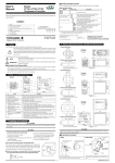
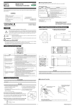
9
<<Contents>> <<Index>>
■ Function Block Diagram for Heating/Cooling Type
PV input
terminals
11 , 12 and 13
Communication
terminals 23 to 27
PV INPUT
RS485
Contact input
DI1
DI2
Input selection
Unit selection
Input range conversion
Input bias
Input filter
SP.NO
Target setpoints 1 to 4
REMOTE
SP.NO=0
LOCAL
SP.NO=1 to 4
Target setpoint
ramp-rate function
Manual operation
Control computation
MAN
A/M
AUTO
AUTO (ON)/MAN (OFF) switching
Heating/cooling
computation
Cooling-side
output limiter
Heating-side
output limiter
Heating-side
preset output
*1
*1
OT
15 V loop
power supply
OT
Heating-side
output
Cooling-side
preset output
Retransmission
output
Cooling-side
output
Alarm function
RET
DO3
OUTPUT1
Current or pulse
terminals
16 and 17
OUTPUT1
OUTPUT2
DO1
OUTPUT2
/LPS
Relay
Relay
Current or pulse
terminals
terminals
1 , 2 and 3
14 and 15
DO2
Alarm 1 Alarm 2
Current
terminals
14 and 15
*1: If the setup parameter DIS (DI function selection) is set to “4”,
when the contact input 2 is ON (run state), that controller outputs the preset output value.
Terminal
Parameter
Function
Analog signal
Contact signal
Front panel key
Legend
All Rights Reserved. Copyright © 2000, Yokogawa Electric Corporation
GS 05D01D02-02E
4th Edition Apr. 02, 2007-00