1
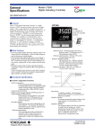
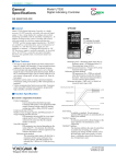
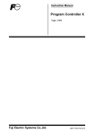
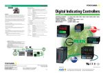
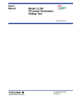
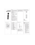
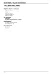
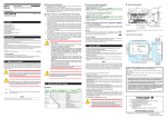
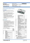
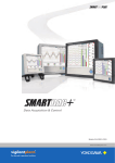
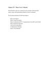
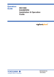
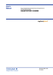
<<Contents>> <<Index>>
General
Specifications
Model UT351
Digital Indicating Controller
with Active Color PV Display
GS 05D01D12-01E
■ General
Model UT351 Digital Indicating Controller is a highly
accurate 1/4 DIN controller, provided with the PV display
color changing function “Active Color PV Display.” It has
a large display for readings, universal input/output and
excellent monitoring operability with Auto/Man switching
key. In addition, auto-tuning, the overshoot suppressing
function “SUPER”, the hunting suppressing function
“SUPER2” and heating/cooling control are available as
control functions, and a retransmission output and 15V DC
loop power supply are also equipped as standard. A
communication function or 24V DC loop power supply is
available optionally. As described above, the UT351 is a
controller provided with higher functions and capability.
UT351
Indication in
green or red
color
UT351E
“E” indicates the
model with expanded
functions.
■ Main Features
• Extra-large digital display allows the indicated values to be
read even from a long distance. LEDs of 20mm height are
used for the PV display.
• The PV display color changing function “Active Color PV
Display” is provided. PV display color is changed from
green to red and vice versa when an alarm occurs or
deviation becomes large. The color also can be fixed in
green or red.
• Universal input and output enable users to set or change
freely the input type PV (thermocouple, RTD, or mV), PV
input range, and type of control output(4 to 20mA current,
voltage pulse, or relay contact) from the front panel.
• Parameters can easily be set using a personal computer.
(“Parameter setting tool (model LL100)” sold separately is
required.)
• Various communication functions are provided. Communication is possible with personal computer, programmable
logic controller, and other controllers.
Reference point method:
The PV input range is divided into a maximum of three zones with up to two reference
points, and PID parameters are selected (No. 1
PID to No. 3 PID) for every zone.
Reference point = PV input range (0%) Reference
point 1 Reference point 2 PV input
range (100%)
Reference point hysteresis = Fixed to 0.5% of the PV
input range span.
Reference deviation method:
PID parameters (No. 4 PID) are selected
when the deviation exceeds the reference
deviation. This process takes precedence
over the reference point method.
Reference deviation = OFF or 0.1 to 100.0% of PV
input range span
PV input range (100%)
■ Functional Specifications
Reference deviation
No.3PID
Reference deviation
● Control Computation Functions
Control computation:
Can be selected from the following types:
Continuous PID control, Time-proportional PID
control, Heating/Cooling control (for heating/
cooling type only) or Relay ON/OFF control.
Control cycle time: 250 ms
Number of sets of target setpoints and PID parameters: 4
Target setpoint and PID selection:
PID parameters are provided for every target
setpoint and the set of PID parameters are
selected at the same time that the setpoint
number is selected.
Zone PID selection:
PID parameters are selected depending on the
value of the PV. For selection, the reference
point (PID parameter selection setpoint) or the
reference deviation is used.
Reference point 2
No.2PID
Reference point 1
No.1PID
PV input range (0%)
Measured value (PV)
Auto-tuning:
Available as standard. If auto-tuning is
operated, PID constants are automatically set
(limit cycle method).
“SUPER” function:
Overshoots generated by abrupt changes in the
target setpoint or by disturbances can be
suppressed.
GS 05D01D12-01E
©Copyright Oct. 2002
5th Edition Mar. 2005
2
<<Contents>> <<Index>>
“SUPER2” function:
The function stabilizes the state of control that
is unstable due to hunting, etc. without
requiring any change in PID constans, when
the load and/or gain varies greatly, or when
there is a difference between the characteristics of temperature zones.
Control Parameters Setting Range
Proportional band = 0.1 to 999.9%
0.0 to 999.9% for heating/cooling control,
0.0% for ON/OFF control
Integral time = 1 to 6000s, or OFF (manual reset)
Derivative time = 1 to 6000s, or OFF
Manual reset value = -5.0 to 105.0% of output range
(functions when integral time is off.)
ON/OFF control hysteresis = 0.0 to 100.0% of PV input
range span (0.1 to 0.5% for heating/cooling
control)
Setpoint rate-of-change setting = OFF, or 0.0 to 100.0%/h
or min of PV input range span.
A PV tracking function operates automatically
when the setpoint is changed, the power is
turned on, or the mode is changed from
manual to automatic.
Direct/reverse action:
The output increase/decrease direction can be
defined corresponding to a positive or
negative deviation.
For heating/cooling control, it is fixed; for the
heating side output, reverse, for the cooling
side output, direct.
Anti-reset windup:
When controller output is limited, normal
integration is superseded by an anti-reset
windup computation to suppress overintegration.
Control output cycle time = 1 to 1000s for Timepropotional PID control (the cooling side
output cycle time is also the same when
heating/cooling control is used).
Preset output value = -5.0 to 105.0% of output range
Output tracking:
Whether the output bump is provided or not
can be selected by changing the PID control
mode.
Output limiter
Upper limit = Lower limit to 105.0% of output
range
Lower limit = -5.0% of output range to upper
limit
Heating/cooling dead band = -100.0 to 50.0% for output
range
● Signal Computation Functions
PV input computation:
Bias addition (-100.0 to 100.0% of PV input
range span), and first-order lag filter (time
constant OFF or 1 to 120s)
Contact input function:
Target setpoint selection, Auto/Man operating
mode switching, key lock parameter show/
hide switching
Target setpoint selection can be done for
either a 2-setpoint or 4-setpoint selection.
• If the 2-setpoint selection is set, Auto/Man
mode switching can be used as well.
All Rights Reserved. Copyright © 2002, Yokogawa Electric Corporation
• If the 4-setpoint selection is set, Auto/Man
switching and key lock parameter show/hide
switching cannot be used together.
If key lock parameter show/hide switching is
used, target setpoint selection and Auto/Man
mode switching cannot be used.
● Alarm Functions
Twenty-four types of alarm functions are provided. The
alarm status is indicated by the alarm lamp on the front
panel. Also, three points among them can be output as relay
contact outputs.
Alarm types:
PV high limit, PV low limit, Deviation high
limit, Deviation low limit, De-energized on
deviation high limit, De-energized on
deviation low limit, Deviation high and low
limits, High and low limits within deviation,
De-energized on PV high limit, De-energized
on PV low limit, SP high limit, SP low limit,
Output high limit, Output low limit, Deviation
high limit for target setpoint, Deviation low
limit for target setpoint, De-energized on
deviation high limit alarm for target setpoint,
De-energized on deviation low limit alarm for
target setpoint, Deviation high and low limits
fot target setpoint, Deviation within high and
low limits for target setpoint, Heater burout
alarm, Sensor grounding alarm, Fault
diagnostic alarm, and FAIL output.
Alarm output:
3 points. Any three points can be output as
contact outputs among the above alarms. For
heating/cooling control, if cooling side output
is output as a relay contact, up to two alarm
outputs can be used.
Setting ranges for PV, deviation, setpoint and output alarms:
PV/setpoint alarm:
-100.0 to 100.0% of PV input range
Deviation alarm:
-100.0 to 100.0% of PV input range span
Output alarm:
-5.0 to 105.0% of output range
Alarm hysteresis:
0.0 to 100.0% of PV input range span
Delay timer:
0.00 to 99.59 (minute, second)
An alarm is output when the delay timer
expires after the alarm setpoint is reached.
Setting for each alarm is possible.
Stand-by action:
Stand-by action can be set to make PV/
deviation alarm OFF during start-up or after
SP change until SP reaches the normal region.
Heater burnout alarm (optional):
Two circuits incorporated.
A heater burnout alarm is output if the heater
current consumption is the burnout detection
value or less. This alarm can be used for
Relay ON/OFF control or time-proportional
PID control.
Heater current setting range: 0.0 to 50.0 A
Setting accuracy: ± 5% of span ± 1 digit
Heater current detecting resolution: 0.5 A
Time required until burnout detection is on:
0.13s minimum
Burnout sensor model: CTL-6-S-H(URD Co. Ltd.)
GS 05D01D12-01E
5th Edition Mar. 01, 2005-00
3
<<Contents>> <<Index>>
Sensor grounding alarm:
An alarm is output after detecting a change in
control output. If the moving average * of
control output is out of the setting range
(between the high and low limits of the on/off
rate) in spite of the deviation being within a
fixed range (on/off rate detection band) and
control being in stable condition, the sensor is
judged to be in a grounding condition.
* Moving average refers to the average value for output
values sampled (five times) in every cycle time.
High- and low-limit setting range of on/off rate:
-5.0 to 105.0% of output range
Detection band of on/off rate:
0.0 to 100.0% of PV input range span.
Fault diagnostic alarm:
Input burnout, A/D conversion error,
thermocouple reference junction compensation error
FAIL output:
Abnormality in software or hardware.
When in FAIL, control output, retransmission
output and alarm output become 0% or OFF.
● Display and Operation Functions
PV display: 4-digit digital display for engineering data
Setpoint display:
Various data, such as the setpoint (SP), are
displayed by selection on the 4-digit digital
display.
Status indicating lamps:
3 alarm indicator lamps: AL1, AL2, AL3
3 setpoint number indicator lamps:
SP2, SP3, SP4 (Go out when SP1 is
selected.)
MAN operation mode lamp:
MAN (Lit in MAN mode.)
PV display color changing function “Active Color PV
Display” :
(Factory-set default : Fixed in red mode)
This function automatically changes PV
display color by the action described below.
Green-to-red or red-to-green changing action
is selectable.
Link to alarm 1 mode :
Alarm OFF : green, Alarm ON : red
Setting of Alarm OFF : red, Alarm ON :
green is possible.
Link to alarms 1 and 2 mode :
Alarm OFF : green, Alarm ON : red
Setting of Alarm OFF : red, Alarm ON :
green is possible.
SP deviation mode :
Within the preset SP deviation : green,
Out of the preset SP deviation : red
Setting of within the preset SP deviation :
red,
Out of the preset SP deviation : green is
possible.
Deviation band is changeable using a
parameter. The setting of either high limit
deviation or low limit deviation is also
possible.
PV limit mode :
Within the preset PV range : green,
Out of the preset PV range : red
Setting of within the preset PV range : red,
Out of the preset PV range : green is
possible.
The range (high limit and low limit) is
changeable using a parameter.
Fixed color mode :
PV display color is fixed in green or red.
Operation keys:
쑶and 쑴 keys:
Increase or decrease setpoints and various
parameters.
SET/ENT key:
Used for data setting or call-up/selection of
various parameters
A/M key: Switching of operation mode (Auto/Man)
SELECT display:
A panel where operating parameters that are
frequently changed during operation can be
selected and registered. For example, by
registering the alarm -1 setpoint in the
SELECT display, the setpoint can easily be
displayed during operation.
Security function:
An operation-inhibiting mode using a
password is provided.
LED display unit (for PV)
Status lamps
Alarm(AL1, 2, 3), Manual(MAN).
Setpoint No. (SP2, 3, 4) in use.
Communication port for light loader
Light receiving and emitting part for communication
with parameter setting tool via PC.
Operational keys
Display PV, and error code when
error is detected.
Active color PV display
Display in green or red color.
LED display unit (for SP)
Display setpoint (SP), output value,
and setting item/value of parameters.
Increase/Decrease the setting data (쑶, 쑴)
Select parameter/Enter the setting data (SET/ENT)
A/M mode switching (A/M)
All Rights Reserved. Copyright © 2002, Yokogawa Electric Corporation
GS 05D01D12-01E
5th Edition Mar. 01, 2005-00
4
<<Contents>> <<Index>>
● Communication Functions(optional)
This controller has a communication function and can be
connected to a personal computer, programmable logic
controller or other GREEN series controllers.
Communication protocol
Computer link communication:
Communication protocol with a personal
computer.
Ladder communication:
Communication protocol with programmable logic controller.
MODBUS communication:
Communication protocol with a personal
computer or PLC.
Coordinated operation:
Communication protocol to coordinated
operation with two or more GREEN series
controllers. The UT351 can be connected as
a master station or a slave station.
Communication interface
Communication protocol:
Computer link, ladder communication,
MODBUS or coordinated operation.
Standards: EIA RS485
Maximum number of connectable controllers:
31 GREEN series controllers
Maximum communication distance: 1,200 m
Communication method:
Two-wire half duplex or four-wire half
duplex, start-stop synchronization, nonprocedural.
Communication rate: 600, 1200, 2400, 4800, or 9600 bps
Examples of Communication System Configuration Diagram
(1) Computer link communication/MODBUS communication
(2) Ladder communication
Personal computer
PLC
UT351/UT321
Digital indicating controller
UT351/UT321
Digital indicating controller
(3) Coordinated operation
UP351 Program controller
or UT351/UT321 Digital indicating controller
UT351/UT321
Digital indicating controller
All Rights Reserved. Copyright © 2002, Yokogawa Electric Corporation
GS 05D01D12-01E
5th Edition Mar. 01, 2005-00
5
<<Contents>> <<Index>>
■ Hardware Specifications
PV Input Signal
Number of input points: 1
Input system:
The type of input and instrument range can be
specified using the table of PV input shown
below by key operation or communication.
Input type, instrument range and measurement accuracy:
Refer to the table below.
Input Type
Input range
code
Instrument range (˚C)
OFF
K
1
-200 to 1370C
-300 to 2500F
2
3
-199.9 to 999.9C
-199.9 to 500.0C
0 to 2300F
-199.9 to 999.9F
J
T
4
5
-199.9 to 999.9C
-199.9 to 400.0C
-300 to 2300F
-300 to 750F
B
6
7
0.0 to 400.0C
0 to 1800C
-199.9 to 750.0F
32 to 3300F
Thermocouple
Measurement accuracy*1
Instrument range (˚F)
Unspecified(when shipped from the factry)
Set the data item PV input Type"IN" to the OFF option to leave the PV input type undefined.
0.1% of instrument range 1 digit for
temperatures equal to or higher than 0 C,
0.2% of instrument range 1 digit for
temperatures below 0 C
0.15% of instrument range 1 digit for
temperatures equal to or higher than 400 C
5% of instrument range 1 digit for
temperatures below 400 C
0.15% of instrument range 1 digit
S
8
0 to 1700C
R
N
9
10
0 to 1700C
32 to 3100F
-200 to 1300C
-300 to 2400F
0.1% of instrument range 1 digit
0.25% of instrument range 1 digit for
temperature below 0 C
0.1% of instrument range 1 digit for
temperatures equal to or higher than 0 C
0.2% of instrument range 1 digit for
32 to 3100F
E
L (DIN)
U (DIN)
11
12
13
-199.9 to 999.9C
-199.9 to 900.0C
-199.9 to 400.0C
-300 to 1800F
-300 to 1300F
-300 to 750F
W (DIN)
14
15
0.0 to 400.0C
0 to 2300C
-199.9 to 750.0F
32 to 4200F
Platinel 2
PR20-40
16
17
0 to 1390C
0 to 1900C
32 to 2500F
32 to 3400F
temperatures below 0 C
0.2% of instrument range 1 digit
0.1% of instrument range 1 digit
0.5% of instrument range 1 digit for
temperatures equal to or higher than 800 C
No guarantee of accuracy for temperatures
RTD
W97Re3-W75Re25
JPt100
Pt100
Standard
signal
DC voltage
0.4 to 2V
1 to 5V
0 to 2V
0 to 10V
-10 to 20mV
0 to 100mV
18
30
0 to 2000C
-199.9 to 500.0C
32 to 3600F
-199.9 to 999.9F
31
35
36
37
40
41
50
51
55
56
-150.0 to 150.0C
-199.9 to 850.0C
-199.9 to 500.0C
-150.0 to 150.0C
-199.9 to 300.0F
-300 to 1560F
-199.9 to 999.9F
-199.9 to 300.0F
0.400 to 2.000
1.000 to 5.000
0.000 to 2.000
0.00 to10.00
-10.00 to 20.00
0.0 to 100.0
Scaling is enable in the following
4 range.
-1999 to 9999
-199.9 to 999.9
-19.99 to 99.99
-1.999 to 9.999
below 800 C
0.2% of instrument range 1 digit
0.1% of instrument range 1 digit (Note 1)
(Note 2)
0.2% of instrument range 1 digit (Note 1)
0.1% of instrument range 1 digit (Note 1)
(Note 2)
0.2% of instrument range 1 digit (Note 1)
0.1% of instrument range 1 digit
The read-out range can be scaled between 1999 and 9999.
Note 1: The accuracy is 0.3C of instrument range 1 digit for a temperature range from 0 to 100C.
Note 2: The accuracy is 0.5C of instrument range 1 digit for a temperature range from -100 to 0C and 100 to 200C.
*1: Performance in the standard operating conditon (at 23C 2C, 5510%RH, and 50/60Hz power frequency)
*2: To receive a 4 to 20 mA DC signal, select a Standard signal of 1 to 5 V DC and connect it to a 250 Ω resistor.
This resistor is optional Model: X010-250-2 (resistor with M3.5 crimp-on-terminal lugs)
Sampling period: 250 ms
Burnout detection:
Functions with a thermocouple (TC), RTD,
standard signal 0.4 to 2 V DC, and 1 to 5 V DC.
Can be specified as upscale, downscale, and off.
For standard signal, judged as burnout at 0.1
V or less.
Input bias current: 0.05 µA (for TC/RTD b-terminal)
Measuring current(RTD): about 0.13mA
Input resistance:
1 MΩ or more for TC/mV input
About 1 MΩ for DC voltage input
All Rights Reserved. Copyright © 2002, Yokogawa Electric Corporation
Allowable signal source resistance:
250 Ω or less; effect of permissible signal
source resistance 0.1 µV/Ω or less for TC/mV
input 2 k Ω or less; effect of permissible
signal source resistance 0.01%/100 Ω or less
for DC voltage input
Allowable leadwire resistance:
Max. of 150 Ω/wire (resistance in each of
three wires must be equal) for RTD input
However, 10 Ω/wire for a maximum range of
-150.0 to 150.0°C.
Effect of permissible leadwire resistance
± 0.1°C/10 Ω or less
GS 05D01D12-01E
5th Edition Mar. 01, 2005-00
6
<<Contents>> <<Index>>
Allowable input voltage:
± 10 V DC for TC/mV/RTD input
± 20 V DC for DC voltage input
Noise rejection ratio:
Normal mode 40 dB (50/60 Hz) or more
Common mode 120 dB (50/60 Hz) or more
Reference-junction compensation error:
± 1.0°C (15 to 35°C),
± 1.5°C (0 to 15°C, 35 to 50°C)
Applicable standards: JIS, IEC, or DIN(ITS-90) for TC
and RTD
24V DC Loop Power Supply for Sensor
The controller supplies power to a two-wire transmitter.
Place a resistor (10 to 250Ω) between the controller and the
transmitter, convert a current signal to a voltage signal, and
read it from the PV input.
21.6 to 28.0 V DC, maximum supply current is about 30mA
(only for models with 24V DC loop power supply).
■24 V DC Power Supply Wiring to Two-wire Sensor
12
External
resistor 250Ω
(Note)
Two-wire transmitter
PV input
1 to 5 V DC signal
13
21
4-20mADC
22
Loop power
supply
21.6 to
28.0 V DC
Note: Connecting a 250 Ω resistor to the termanals is optional.
Model: X010-250-2 (resistor with M3.5 crimp-on terminal lugs)
Retransmission Output
Either PV, target setpoint, or control output is output. Either
the retransmission output or the 15V DC loop power supply
can be used.
Number of output points: 1
Output signal: 4 to 20 mA DC
Load resistance: 600 Ω or less
Output accuracy: ± 0.3% of span
* Performance in the standard operating
conditions (at 23± 2°C, 55± 10% RH, and 50/
60 Hz power frequency)
15V DC loop power supply:
Supply voltage is 14.5 to 18.0 V DC. Maximum supply
current is about 21 mA (with a protection circuit for a field
short-circuit).
Control Outputs
The control output is of a universal scheme and can be
selected from the following types of outputs. In the case of
heating/cooling control, it is also selectable from these
outputs. However, if the cooling side output is a relay
contact output, the alarm-3 cannot be used, and similarly if
the cooling side output is a voltage pulse or current output,
the retransmission output/15 V DC sensor power supply
cannot be used.
Current output
Number of output points: 1 or 2 (2 for heating/cooling type)
switchable to voltage pulse output.
Output signal: 4 to 20 mA
Load resistance: 600 Ω or less
Output accuracy: ±0.3% of span
* Performance in the standard operating
conditions (at 23± 2°C, 55± 10% RH, and
50/60 Hz power frequency)
All Rights Reserved. Copyright © 2002, Yokogawa Electric Corporation
Voltage pulse output
Number of output points: 1 or 2 (2 for heating/cooling type)
switchable to voltage pulse output.
Output signal:
On voltage = 12 V DC or more (load
resistance of 600 Ω or more; current on
short-circuiting about 30 mA)
Off voltage = 0.1 V DC or less
Resolution: 10 ms
Relay contact output
Number of output points: 1 or 2 (2 for heating/cooling type)
Output signal:
Three terminals for NC, NO, and Common
transfer-contact
Contact rating:
250 V AC, 3 A or 30 V DC, 3A (resistive load)
Resolution: 10 ms
Contact Inputs
Usage:
Target setpoint selection, Auto/Man mode
switching, or Key lock parameter show/hide
switching
Number of input points: 2
Input type: Non-voltage contact input or transistor open
collector input
Input contact rating: 12 V DC, 10 mA or more (for nonvoltage contact input)
On/off determination:
For non-voltage contact input,
ON = contact resistance of 1 kΩ or less,
OFF = contact resistance of 20 kΩ or more.
For transistor contact input,
ON = 2 V or less,
OFF = leakage current of 100 µA or less.
Minimum retention time for status detection: about 1 second
Contact Outputs
Usage:
Alarm output, FAIL output, and others
Number of relay contact output points: 3
Relay contact rating: 240 V AC, 1 A or 30 V DC, 1 A
(COM terminal is common for every contact
output.)
● Display Specifications
PV display: 4-digit, 7-segment green or red LED;
character height - 20 mm
Setpoint display:
4-digit, 7-segment red LED; character height 9.3 mm
Status indicating lamps: LEDs
● Conformance to Safety and EMC Standards
Safety: Complies with IEC/EN61010-1 (CE), approved by
C22.2 No.61010-1, approved by UL508.
Installation category : CAT. II Pollution
degree: 2 (IEC/EN61010-1, C22.2 No.61010-1)
Measurement category : I (CAT. I : IEC/
EN61010-1)
Rated measurement input voltage : 10V DC
max.(across terminals), 300V AC max.(across
ground)
Rated transient overvoltage : 1500V (Note)
Note : It is a value on the safety standard
which is assumed by IEC/EN61010-1 in
Measurement category I, and is not the value
which guarantees an apparatus performance.
EMC standards: Complies with EN61326, EN61000-3-2,
EN61000-3-3 and EN55011 (CE).
AS/NZS 2064 compliant (C-Tick).
Class A Group 1.
During test, the controller continues to operate
with the measurement accuracy within ±20%
of the range.
GS 05D01D12-01E
5th Edition Mar. 01, 2005-00
7
<<Contents>> <<Index>>
● Construction, Mounting, and Wiring
Construction: Dust-proof and Drip-proof front panel
conforming to IP55.
For side-by-side close installation, the
controller loses its dust-proof and drip-proof
protection.
Material: ABS resin and polycarbonate
Case color: Black
Weight:
Approx. 1 kg or less
External dimensions:
96 (width) × 96 (height) × 100 (depth) mm
Mounting :
Direct panel mounting; mounting
bracket, one each for upper and lower
mounting
+0.8
Panel cutout dimensions: 92 +0.8
0 (width) × 92 0 (height) mm
Mounting attitude:
Up to 30 degrees above the horizontal. No
downward tilting allowed.
Wiring:
M3.5 (ISO 3.5 mm) screw terminals (signal
wiring and power/ground wiring as well)
● Power Supply Specifications and Isolation
Power supply: Rated at 100 to 240 V AC (±10%), 50/60 Hz
Power consumption: MAX. 20 VA (MAX. 8.0 W)
Internal fuse rating: 250 VAC, 1.6A time-lug fuse
Memory back-up: Non-volatile memory (Service life
approx. 100,000 times of writings)
Withstanding voltage:
1500 V AC for 1 minute between primary and
secondary terminals.
1500 V AC for 1 minute between primary and
ground terminals.
1500 V AC for 1 minute between ground and
secondary terminals.
500VAC for 1minute between two secondary
terminals.
Primary terminals = Power and relay output terminals
Secondary terminals = Analog I/O signal terminals,
voltage pulse output terminals,
contact input terminals
Isolation resistance:
20 MΩ or more when 500 V DC voltage is
applied between the power terminals and
ground terminal.
Grounding:
Class D grounding (Class 3 grounding)
(grounding resistance of 100 Ω or less)
All Rights Reserved. Copyright © 2002, Yokogawa Electric Corporation
● Isolation specifications:
PV input terminal:
Isolated from other I/O terminals. Not
isolated from internal circuits.
15 V DC loop power supply terminals:
Not isolated from 4-20mA analog output
and voltage pulse control output. Isolated
from other I/O terminals and internal circuit.
24 V DC loop power supply terminals:
Isolated from other I/O terminals and
internal circuit.
Control output (current or voltage pulse) and retransmission terminals: Not isolated between control
output terminals and retransmission output
terminals. Isolated from other I/O terminals
and internal circuits.
Relay contact control output terminals:
Isolated from other I/O terminals and
internal circuits.
Contact input terminals:
Not isolated from other contact input
terminals mutually, and communication
terminals. Isolated from other I/O
terminals and internal circuits.
Relay contact alarm output terminals:
Isolated from other I/O terminals and
internal circuits.
RS-485 communication terminals:
Not isolated from contact input terminals.
Isolated from other I/O terminals and
internal circuits.
Power supply terminals:
Isolated from other I/O terminals, ground
terminal, and internal circuits.
Ground terminal:
Isolated from other I/O terminals, power
terminals, and internal circuits.
● Environmental Conditions
Normal operating conditions:
Ambient temperature: 0 to 50°C (40°C or less for
mounting of instruments side-by-side)
Ambient temperature change limit: 10°C /h or less
Ambient humidity: 20 to 90% RH (no condensing)
Magnetic field: 400 A/m or less
Continuous vibration (5 to 14 Hz):
Peak-to-peak amplitude of 1.2 mm or less
Continuous vibration (14 to 150 Hz):
4.9 m/s2 or less
Short-period vibration: 14.7 m/s2, 15s or less
Shock:
147 m/s2 or less, 11 ms
Installation altitude: 2,000 m or less above sea level
Warm-up time
30 minutes or more
Transportation and storage conditions:
Temperature: -25 to 70°C
Temperature change limit: 20°C /h or less
Humidity: 5 to 95% RH
Effects of operating conditions
Effect of ambient temperature:
For voltage or TC inputs:
Whichever is greater, ± 1µV/°C or
±0.01% of F.S./°C
For RTD inputs:
±0.05°C/°C (ambient temperature) or less
for RTD input
For analog output: ±0.05% of F.S./°C or less
Effect of power supply fluctuation (within rated voltage
range):
For analog input:
Equal to or less than whichever is greater,
± 1 µV/10 V or
± 0.01% of F.S./10 V
For analog output: ±0.05% of F.S./10 V or less
GS 05D01D12-01E
5th Edition Mar. 01, 2005-00
8
<<Contents>> <<Index>>
■ Function Block Diagram for Standard Type
PV input
terminals
11 , 12 and 13
Communication
terminals 23 to 27
INPUT
RS485
Contact input
(When parameter DIS=1)
DI1
DI2
Input selection
Unit selection
Input range conversion
Input bias
Input filter
SP.NO
Target setpoints 1 to 4
REMOTE
SP.NO=0
LOCAL
SP.NO=1 to 4
Target setpoint
ramp-rate function
Manual operation
Control computation
MAN
A/M
AUTO
AUTO (ON)/MAN (OFF) switching
Preset output
Output limiter
STOP
RUN
*1
24 V loop
power supply
15 V loop
power supply
OT
Retransmission
output
Control
output
LPS
OUTPUT1
Terminals
21 and 22
Current or pulse
terminals
16 and 17
OUTPUT1
Relay
terminals
1 , 2 and 3
Alarm function
RET
OUTPUT2
/RET
DO1
DO2
DO3
Alarm 1 Alarm 2 Alarm 3
Current
terminals
14 and 15
*1: If the setup parameter DIS (DI function selection) is set to “4”,
when the contact input 2 is ON (STOP state), that controller outputs the preset output value.
Terminal
Parameter
Function
Analog signal
Contact signal
Front panel key
Legend
All Rights Reserved. Copyright © 2002, Yokogawa Electric Corporation
GS 05D01D12-01E
5th Edition Mar. 01, 2005-00
9
<<Contents>> <<Index>>
■ Function Block Diagram for Heating/Cooling Type
PV input
terminals
11 , 12 and 13
Communication
terminals 23 to 27
INPUT
RS485
Contact input
(When parameter DIS=1)
DI1
DI2
Input selection
Unit selection
Input range conversion
Input bias
Input filter
SP.NO
Target setpoints 1 to 4
REMOTE
SP.NO=0
LOCAL
SP.NO=1 to 4
Target setpoint
ramp-rate function
Manual operation
Control computation
MAN
A/M
AUTO
AUTO (ON)/MAN (OFF) switching
Heating/cooling
computation
Cooling-side
output limiter
Heating-side
output limiter
Heating-side
preset output
*1
*1
OT
15 V loop
power supply
OT
Heating-side
output
Cooling-side
preset output
Retransmission
output
Cooling-side
output
Alarm function
RET
DO3
OUTPUT1
Current or pulse
terminals
16 and 17
OUTPUT1
OUTPUT2
DO1
OUTPUT2
/RET
Relay
Relay
Current or pulse
terminals
terminals
1 , 2 and 3
14 and 15
DO2
Alarm 1 Alarm 2
Current
terminals
14 and 15 *2
*1: If the setup parameter DIS (DI function selection) is set to 4 ,
when the contact input 2 is ON (STOP state), that controller outputs the preset output value.
*2: Unavailable when cooling-side control output is current or pulse.
Terminal
Parameter
Function
Analog signal
Contact signal
Front panel key
Legend
All Rights Reserved. Copyright © 2002, Yokogawa Electric Corporation
GS 05D01D12-01E
5th Edition Mar. 01, 2005-00
All Rights Reserved. Copyright © 2002, Yokogawa Electric Corporation
10
9
8
GS 05D01D12-01E
CT
CT
30
28
29
COM
CT2
CT1
Heater current
detection input
30
29
20
19
18
17
16
15
17 -
16 +
4-20 mA DC,
voltage pulse
(12 V)
Control output
Current/voltage
pulse output
21.6-28.0VDC
(30 mA DC max.)
Common
No function
No function
Common
AUTO when DI2=ON
MAN when DI2=OFF
2.SP when DI1=ON
1.SP when DI1=OFF
OT=1
Time proportional control
Voltage pulse output (terminals 16 and 17 )
Time proportional control
Relay output (terminals 1 , 2 and 3 )
OT=2
Current output
(terminals 16 and 17 )
OT=3
Common
DI2 OFF OFF ON ON
DI1 OFF ON OFF ON
On-off control
Relay output (terminals 1 , 2 and 3 )
Common
No function
When DIS=2
When DIS=3
switching target
Hides the LOCK parameter when DI1=ON. When SP
1 to 4:
Shows the LOCK parameter when DI1=OFF.
1.SP2.SP3.SP 4.SP
Correspondence between parameter OT and control output types
OT=0 (factory-shipped setting)
Note:Select this
option from the
OT parameter.
13 -
12 +
TC input
4-20 mA DC
15 -
14 +
14.5-18.0VDC
(21 mA DC max.)
15 V DC loop power supply
15 -
14 +
Retransmission output
13 -
12 +
mV/V input
13 B
12 b
11 A
RTD input
UT
Load resistance: 600 Ω or less
+5V
COM
DI2
DI1
Contact rating: 12 V DC, 10 mA or more
COM 20
DI2 18
+5V
Transistor contact
20
18
19
Note: External Contact Input
If the power is turned on when the external contact input is OFF, the mode
(SP.NO or A/M) existing before the power is turned off will be continued.
(except for RUN/STOP)
Common
STOP when DI2=ON
RUN when DI2=OFF
Contact
* If 15 V DC loop power supply is used,
retransmission output cannot be used.
2.SP when DI1=ON DI1
19
1.SP when DI1=OFF
When DIS=4
250 Ω 4-20mA
Note: Connecting a 250 Ω resistor to the terminals is
optional.
Model: X010-250-2 (resistor with M3.5 crimp-on terminal
lugs)
13 -
12 +
set the PV input type to 1-5 V DC (setpoint “41”).
* When receiving 4-20 mA DC current signals,
䊏 Receiving 4-20 mA DC Current
Signals with the Controller
* PV retransmission is configured at factory
before shipment.
PV input * Not configured at factory before shipment
Correspondence between parameter DIS and external contact input functions
When DIS=OFF When DIS=1 (Factory-shipped setting)
* OT is a setup parameter. You can change the settings of the parameter OT to change the control output type.
* This wiring is only
possible for a controller
with a heater burnout
alarm.
10
9
28
27
7
8
26
6
25
5
14
13
12
11
22 -
21 +
* DIS is a setup parameter.
Changing DIS setpoint allows you to change the function of external contact input.
Before carrying out wiring, turn off the power
to the controller and check that cables to be
connected are not alive with a tester or the
like because there is a possibility of electric
shock.
CAUTION
Allowable range: 100 to 240 V AC (10%)
(free voltage)
50/60 Hz shared
N
L
Power supply
Power supply
23
24
3
COM 7
Common
Relay contact rating: 240 V AC, 1 A
30 V DC, 1 A (resistance load)
Relay
4
22
AL3 4
Alarm-3 output
21
1
2
AL2 5
Alarm-2 output
UT
SG
AL1 6
27
RDA(-)
Alarm-1 output
Alarm output
26
25 RDB(+)
Note: Select this option from
* Wiring can only be carried
the OT parameter.
RS-485 communication * Wiring can only be carried out
out for controllers with
* Time proportional PID
for controllers with
24 V DC loop power supply.
relay contact output is
communication functions.
24 V DC loop
configured at factory
23 SDB(+)
Maximum baud rate: 9600 bps
power supply
before shipment.
24 SDA(-)
Contact rating: 250 V AC, 3 A
30 V DC, 3 A (resistance load)
2
3
NO
1
COM
NC
Relay contact output
Control output
■ Standard Type, Terminal Arrangements
<<Contents>> <<Index>>
10
5th Edition Mar. 01, 2005-00
2
3
NO
COM
* Time proportional PID relay contact output
is configured at factory before shipment.
* Available if 4, 7 or 10 is set in the OT
(Control Output Type) setup parameter.
AL1 6
Relay
UT
All Rights Reserved. Copyright © 2002, Yokogawa Electric Corporation
10
9
8
GS 05D01D12-01E
CT
CT
30
28
29
COM
CT2
CT1
Heater current
detection input
26
22
23
24
25
26
27
28
3
4
5
6
7
8
10
30
29
21
SG
RDA(-)
1
27
2
9
for controllers with communication
functions.
Maximum baud rate: 9600 bps
11
20
19
18
17
16
15
14
13
12
No function
Common
No function
Common
AUTO when DI2=ON
MAN when DI2=OFF
2.SP when DI1=ON
1.SP when DI1=OFF
Heating side: Voltage pulse output
(terminals 16 and 17 )
Cooling side: Relay output
(terminals 4 and 7 )
Heating side: Relay output
(terminals 1 , 2 and 3 )
Cooling side: Relay output
(terminals 4 and 7 )
Heating side: Current output
(terminals 16 and 17 )
Cooling side: Relay output
(terminals 4 and 7 )
OT=6
RTD input
Common
DI2 OFF OFF ON ON
DI1 OFF ON OFF ON
OT=7
Heating side: Relay output
(terminals 1 , 2 and 3 )
Cooling side: Voltage pulse output
(terminals 14 and 15 )
OT=8
Heating side: Voltage pulse output
(terminals 16 and 17 )
Cooling side: Voltage pulse output
(terminals 14 and 15 )
4-20 mA DC
15 -
14 +
4-20 mA DC,
voltage pulse (12 V)
Cooling-side control output
15 -
14 +
Retransmission output
When DIS=4
UT
Common
STOP when DI2=ON
RUN when DI2=OFF
13 -
12 +
250 Ω 4-20mA
set the PV input type to 1-5 V DC (setpoint “41”).
Note: Connecting a 250 Ω resistor to the terminals is
optional.
Model: X010-250-2 (resistor with M3.5 crimp-on terminal
lugs)
Heating side: Current output
(terminals 16 and 17 )
Cooling side: Voltage pulse output
(terminals 14 and 15 )
14.5-18.0VDC
(21 mA DC max.)
Contact
+5V
+5V
COM
DI2
DI1
OT=10
Heating side: Relay output
(terminals 1 , 2 and 3 )
Cooling side: Current output
(terminals 14 and 15 )
OT=11
Heating side: Current output
(terminals 16 and 17 )
Cooling side: Current output
(terminals 14 and 15 )
OT=12
Note: External Contact Input
If the power is turned on
when the external contact
input is OFF, the mode
(SP.NO or A/M) existing before
the power is turned off will
be continued.
(except for RUN/STOP)
Heating side: Voltage pulse output
(terminals 16 and 17 )
Cooling side: Current output
(terminals 14 and 15 )
20
18
19
Transistor contact
* The retransmission output and 15 V DC
loop power supply are not available
if the cooling-side control output is set to
“continuous output” and “voltage pulse output.”
* If 15 V DC loop power supply is used,
retransmission output cannot be used.
15 -
14 +
15 V DC loop power supply
Contact rating: 12 V DC, 10 mA or more
COM 20
DI2 18
2.SP when DI1=ON DI1
19
1.SP when DI1=OFF
OT=9
䊏 Receiving 4-20 mA DC Current
Signals with the Controller
* When receiving 4-20 mA DC current signals,
* PV retransmission is configured at factory before shipment.
13 -
12 +
mV/V input
13 B
12 b
11 A
Correspondence between parameter OT and heating-side/cooling-side output types
Common
No function
When DIS=2
When DIS=3
switching target
Hides the LOCK parameter when DI1=ON. When SP
1 to 4:
Shows the LOCK parameter when DI1=OFF.
1.SP2.SP3.SP 4.SP
The control output types, “relay output” and “voltage pulse output” shown in the table above refer to those of time proportional control.
To change the type to a relay output for on-off control, select “Relay Terminals” and change the setpoint of the proportional band to “0.”
OT=5
OT=4 (factory-shipped setting)
17 -
voltage pulse
(12 V)
Heating-side control output
* Available if 5, 6, 8, 9, 11
Current/voltage
or 12 is set in the OT
pulse output
(Control Output
Type)
setup parameter.
16 + 4-20 mA DC,
13 -
12 +
TC input
PV input * Not configured at factory before shipment
Correspondence between parameter DIS and external contact input functions
When DIS=OFF When DIS=1 (Factory-shipped setting)
* OT is a setup parameter. You can change the settings of the parameter OT to change the control output type.
* This wiring is only possible
for a controller with a heater
burnout alarm.
SDA(-)
25 RDB(+)
24
23 SDB(+)
RS-485 communication * Wiring can only be carried out
* DIS is a setup parameter.
Changing DIS setpoint allows you to change the function of external contact input.
Before carrying out wiring, turn off the power to the
controller and check that cables to be connected are
not alive with a tester or the like because there is
a possibility of electric shock.
CAUTION
Allowable range: 100 to 240 V AC (10%)
(free voltage)
50/60 Hz shared
N
L
Power supply
Power supply
Note: The cooling-side control output is selected if 4, 5 or 6 is
set in the OT (Control Output Type) setup parameter.
The alarm-3 output is not available.
The controller is factory-set to the cooling-side control
output (time proportional PID relay contact output).
Relay contact rating: 240 V AC, 1 A
30 V DC, 1 A (resistance load)
AL2 5
Alarm-3 output
or cooling-side control AL3 4
output (Note)
COM 7
Common
Alarm-2 output
Alarm-1 output
Alarm output/cooling-side control output
Contact rating: 250 V AC, 3 A
30 V DC, 3 A (resistance load)
1
NC
Relay contact output
Heating-side control output
■ Heating/Cooling Type, Terminal Arrangements
<<Contents>> <<Index>>
11
5th Edition Mar. 01, 2005-00
12
<<Contents>> <<Index>>
■ External Dimensions and Panel Cutout Dimensions
Unit: mm
91.8
96
112
Large bracket
100
11
96
Small bracket
1 to 10 mm (Panel thickness)
General installation
Side-by-side close installation
[(N-1)96+92]
+0.8
0
92
+0.8
0
117 min.
(53)
92
145 min.
+0.8
0
92
+0.8
0
"N" stands for the number of controllers to be
installed.
However, the measured value applies if N 5.
(25)
■ Model and Suffix codes
Model
Suffix Code
UT351
Type
Optional functions
Description
Digital indicating controller (provided with retransmission output and 15 V
DC loop power supply as standard)
-0
-2
-3
Standard type
Heating/cooling type
Standard type (with 24 V DC loop power supply)
0
1
2
None
With communication, heater burnout alarm
With heater burnout alarm
Standard Accessories: Brackets (mounting hardware), unit label, User’s Manuals, and User’s Manual (reference) (CD-ROM version)
Terminal cover (optional part) is provided.
■ Items to be Specified when Ordering
Model and suffix codes, necessary/unnecessary of User’s Manual or QIC.
All Rights Reserved. Copyright © 2002, Yokogawa Electric Corporation
GS 05D01D12-01E
5th Edition Mar. 01, 2005-00