1
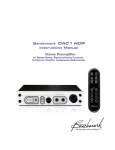
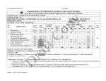
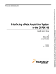
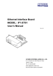
IIA Technical Report Series, No. 10, pp. 1-22, 2012
Report No: IIA-TRS-1012
Development of a Temperature Controller for the Order-sorting
Interference Filters
Ravinder Kumar Banyal∗ and B. Ravindra
Indian Institute of Astrophysics, Bangalore INDIA
(Dated: March 30, 2012)
Abstract
A Fabry-Perot narrow band imager (NBI) is being built for solar studies at IIA [1]. The NBI
has an order sorting pre-filter that selects an optical beam within desired wavelength band. A
constant temperature is required to keep the transmission response of the interference filter stable
during the observations. This technical report describes the design and construction of a digital
temperature sensor and control system for the pre-filter assembly. Temperature measurement and
thermostat operations are performed by DS1621 -a semiconductor IC from Maxim. An I2 C serial
interface (also called 2-wire interface) was developed using computer’s parallel port. The design of
the I2 C interface circuitry and LabVIEW programmes to implement serial communication between
the temperature sensor and the PC are described in details.The device operation is validated and
results of laboratory test are presented.
∗
[email protected]
1
I.
INTRODUCTION
Semiconductor microfabrication techniques are now increasingly used to build on-chip
sensors for a variety of applications in engineering, physics, chemistry and biological sciences
[2]. These sensors contain all the necessary electronics and mechanical hardware on a single
chip. Other attractive features of IC sensors are miniaturized size, reduced cost, multifunctionality and simple digital interface for device control and data transfer. The main focus
of this report however, is to discuss the usage of semiconductor based digital temperature
sensors for thermal control applications. They can represent temperature in digital format
that can be easily read by microprocessor or any other control hardware capable of scanning
the digital lines. Further, the on-chip functionality built to perform logical operations,
analog-to-digital conversion, temperature comparator etc are extremely useful features for
building low-cost dynamic thermal control system. For our application, we have chosen
DS1621 IC test samples supplied by Maxim. Similar temperature ICs from other suppliers
could have also served the purpose equally well.
In general, the need for temperature control in laboratory experiments can manifest
in several ways[3]. There are applications where physical properties of material critically
depend on temperature. In such cases, accurate temperature measurements and control
becomes important to determine, for example, the specific heat of a substances, estimation
of semiconductor band gap, determination of the heat transfer rates, thermal expansion
coefficients of materials and temperature induced wavelength changes in diode lasers. Then
there is another category where temperature control is an essential component in many
experimental apparatuses. Examples include, cooled CCD for astronomical imaging, thermally stabilized cavities for high power lasers, crystal growth ovens, cold traps in vacuum
line and thermal evaporation and coating chambers. The apparatus temperature in these
applications has to be maintained within a few degrees.
This technical report has two broad objectives. The first objective is to introduce an open
source electronic circuit to build an IC based digital temperature measurement and control
(TMC) system. The second objective is to develop a simple I2 C interface (also called 2-wire
interface) programme using National Instruments’ LabVIEW to perform necessary tasks
related to temperature measurements, automatic data collection and thermostat operation.
A 2-wire serial interface for DS1621 IC is created using digital I/O pins of PC’s printer
2
port. We illustrated how to manipulate the printer port pins using LabVIEW’s In Port
and Out Port VIs to implement device read-write operations, which otherwise require a
microcontroller or some dedicated hardware.
Typically, a digital temperature sensor IC requires a microcontroller to support device
communication over the 2-wire bus. An user is expected to have some level of familiarity
with I2 C system protocols and microcontroller hardware to make temperature measurements
with digital ICs. Alternatively, when device synchronization and speed are not absolutely
critical, a software based approach can be used to facilitate the device control and data
flow operations. In general, any programming language which can access (read/write) the
computer ports, can be used to transmitted serial data and control instructions to the I2 C
device. Likewise, the serial data can be read by the software by sampling the digital I/O lines
of the device at periodic intervals. A knowledge of basic electronics and some experience in
high level programming are the only prerequisites to implement this approach.
The report is divided into VII Sections. The principle of semiconductor thermometry
and the functional details of the DS1621 IC temperature sensor are discussed in Section
II. An interface circuit that converts 2-wire device signal to parallel port voltage levels
is presented in the Section III. The necessary features of the I2 protocols for serial data
transfer between PC and I2 device are explained in Section IV. The details of the LabVIEW
software developed to configure DS1621 sensor for TMC operations, are given in Section V.
The temperature regulation of an interference filter build and tested in the laboratory is
discussed in Section VI. Finally, conclusions are presented in Section VII.
II.
PRINCIPLE OF TEMPERATURE MEASUREMENTS
Most commonly used temperature sensors include thermocouple, resistance temperature
detector (RTD), thermistors and silicon-semiconductors. In each case, the analog output
(voltage, current or resistance) of the sensor bears a certain relationship with temperature that forms the basis of measurements [4]. The choice of a particular sensor depends
on the temperature range, linearity, precision and desired accuracy level in the specific
experiment[3]. For instance, thermocouple are capable of making measurements over a wide
temperature range −260◦ C to + 1600◦ C. The RTDs have low drift errors and excellent repeatability over −200◦ C to + 850◦ C. Thermistors are preferred for their high sensitivity to
3
detect minute changes in temperature within −100◦ C to + 150◦ C range.
With the exception of Si-semiconductors, the sensor output is nonlinear and require
lookup table to obtain correct temperature readout. Additionally, analog sensors also need
extra signal conditioning, calibration, A/D convertor, logic comparator and a voltage or a
current amplifier to make their output useful in many practical applications. Basic theory
behind different types of temperature measurements, construction techniques, accuracy and
range can be found in references[3–4]. Henceforth, our discussion will be confined to ICbased digital sensors for simple laboratory requirements where temperature resolution is
limited to about 0.5 − 1◦ C and a large number of experiments can be performed within their
temperature range.
The success of digital thermal sensor can be attributed to two key factors. First being
silicon, which is most commonly used semiconductor material in thermometry and second the
IC fabrication technology that has significantly matured in last few decades. It is now feasible
to build a thermal sensor with all the device functionality integrated on a single Silicon
chip, thus making them extremely compact and cost effective solution for a variety of TMC
applications. These devices operate on the principle of temperature dependent behavior
of voltage-current relationship at semiconductor junctions forming diode or a transistor.
For example, the difference of forward base-emitter voltage (VBE ) between two identical
transistors operating at a constant collector current ratio, is proportional to the absolute
temperature. The temperature is calculated using an in-built bandgap circuit that measures
the difference in bandgap voltage at two different current densities [5, 6]. The bandgap
circuit produces a voltage that varies linearly with temperature. By integrating on-chip
electronic sub-systems, the device functionality of an IC based temperature sensors have been
further enhanced to suit the specific requirements in TMC applications. Temperature ICs are
now commercially available from several reputed companies such as NXP Semiconductors,
Maxim, National Semiconductors, Microchip and Analog Devices. Typical examples include
LM35, LM335 and LM95233-LM95235 series from National Semiconductor and AD590 and
other variants from Analog Devices. As a readily available test samples, we chose DS1621
IC from Maxim for our application. The approach outlined in this paper is amenable to
similar devices from other manufacturers.
4
FIG. 1. Functional diagram of DS1621 temperature sensor.
A.
DS1621 Temperature Sensor
The DS1621 is an 8-pin programmable IC from Maxim with onboard thermal-diode that
is capable of measuring ambient temperature from -55◦ C to +125◦ C. The functional components of the DS1621 hardware are depicted in the block diagram shown in Figure 1. Only a
brief description of relevant features is provided here. Details related to device specifications,
electronic ratings, pin description and operating conditions of the DS1621 can be found in
the product data sheet[7]. Some of the notable features pertaining to on-chip functionality
of the DS1621 are:
• Configuration/Status Register: The DS1621 can be operated either in continuous
temperature conversion mode or one-shot temperature conversions modes. In former
case, DS1621 continuously converts the temperature and stores the results in 2-byte
temperature register. Reading the temperature register does not affect the conversion
process. In one-shot conversion mode, DS1621 performs a single temperature measurement, stores the result in temperature register and then goes to power-shutdown
mode. A read/write 8-bit Configuration/Status register is used for setting the mode
of operation and to read the status of different parameters of the sensor. The least
5
significant bit (LSB, bit-0), for example, is used to set either one-shot (bit-0=1) or
continuous (bit-0=0) temperature conversion mode. The bit-1, determines the output
polarity (“1”= active high, “0” = active low) of the thermostat output pin TOUT .
• Analog-to-Digital Convertor: The in-built analog-to-digital convertor (ADC) is
used for converting the sensor output to binary format. The sequence of binary digits
1 and 0 is passed onto the PC or microcontroller hardware which is then encoded to
decimal equivalent of temperature values. Temperature can be read either as a single
byte (1◦ C resolution) or a two byte (0.5◦ C resolution) data as shown in Figure 2. The
most significant bit (MSB, bit-7) of the 1st byte represents the temperature sign (1
for -ve and 0 for +ve), while the decimal equivalent of the remaining bits (bit-0 to
bit-6) yields the temperature reading in ◦ C. The leading digit (bit-7) of the 2nd byte
determines the 0.5◦ C resolution while all other bits are set to zero. This means 0.5◦ C
should be added to the temperature readout from the 1st byte when the bit-7 of the
2nd byte is high. As an illustration, the 9-bit temperature output, shown in Figure 3
corresponds to -37.5 ◦ C.
• I2 C Bus Interface: The on-chip interface for I2 C bus that allows serial communication via two wires with microcontroller or PC for supporting device read/write
operations.
• Temperature Threshold Registers: Two programmable registers to store, e.g.,
the high (TH ) and low temperature (TL ) limits for thermal control.
• Logic Comparator: A logic comparator for generating digital interrupt signal to
issue alarm, control thermostat operation for temperature regulation or to shut down
an equipment to prevent a catastrophic failure when the measured temperature exceeds
or drops below a preset temperature limits. This feature also relieves the system
controller or PC from continuously reading the temperature. Thermostat control
(TOUT ) with programmable hysteresis is necessary to prevent the fan or heater from
oscillating with the slow changing inputs.
• Device Address Pins: Programmable address lines A0, A1 and A2 to uniquely
identify the device on I2 C bus.
6
• Counter and Slope Register: A counter and slope registers to obtain higher temperature resolution (0.125◦ C). The high resolution is computed using the following
expression:
TEMPERATURE = TEMP READ − 0.25 +
Slope − Count
Slope
(1)
where Temp Read is the 1st byte temperature readout. A Read Slope and a Read
Counter command should be used to obtain these values. The method to obtain high
resolution temperature measurements is explained in reference [8].
FIG. 2. An example of two-byte temperature readout of DS1621.
III.
PRINTER-PORT TO I2 C HARDWARE INTERFACE
The data and command transfer between DS1621 and control hardware take place serially
over a 2-wire bus, commonly known as the I2 C-bus. It was developed by Philips Semiconductor in early 1980s to facilitates simple communication link between digital devices such as
IC-sensors, LCD drivers, general purpose I/O lines, single chip microcontrollers, EEPROM,
A/D and D/A data convertors. The I2 C bus has two lines, namely, a clock line (SCL) and a
serial data line (SDL). Multiple devices can be connected to a single I2 C bus. Each device is
recognized by a software controlled unique address. Communication between the devices is
based on simple master-slave relationship that exits during the data transaction. The data
transfer over 2-wire bus can vary from 100 kbit/s in standard mode, 400 kbit/s in the fast
mode and 3.4 Mbit/s in high-speed mode. Microcontroller or PC is usually the master that
generate clock signals and initiate and terminate the data transfer processes on the bus.
Master is also responsible for ensuring synchronization and arbitration for multi-slave I2 C
bus.
7
Besides microcontroller, virtually any computer port (e.g. serial, parallel or USB) with
digital I/O lines can be utilized to control an I2 C device. Some electronics hardware is,
however, necessary to convert the port specific voltage levels to those used for data communication over the 2-wire bus. The choice of the hardware would depend on the type of
computer port that one selects. For example, an RS-232 to 2-wire interface requires an
adapter to translate from 12 VDC serial port signal to 0-5VDC open drain I2 C standard[9].
Given the steep rise in USB supported peripheral devices in recent years, many variants
of USB to I2 C adapters are commercially available. Apart from added cost, the internal
working and in-system programming of these propitiatory hardware remains unknown to
end users.
One of the simplest ways to control an I2 C device is to use PC’s parallel ports which is
also known as LPT or printer port. Several open source hardware options exits to exploit
the printer port for I2 C communication. Figure 3(a) shows one such interface circuit built
using off-the-shelf electronic components [10, 11]. There are three 8-bit registers associated
with standard 25-pins printer port, namely, Data Register, Control register and Status
register[12]. Data register transfers 8-bits of data to the external devices. Read-only Status
register reports different aspects (e.g. online, out of paper error, busy etc) of the device while
bidirectional Control register is meant to perform tasks of device selection, initialization and
linefeed etc. What is important is that each of these register ports are uniquely mapped
to I/O address space of the PC. For a typical PC, the default Base address of the parallel
port is 0x378 (or it could be 0x278 or 0xBD00). Which means the Data register is mapped
to Base address 0x378. The Status register and Control register would then be at Base +
1 and Base + 2, respectively. The DB-25 pin assignment to the corresponding registers is
shown in Figure 3(b). In next section, we will use Inport and Outport VI of the LabVIEW
to access these ports directly and see how to alter the ON/OFF condition of individual pins
to control the DS1621 temperature IC.
The printer-port pins cannot be connected directly to SCL and SDA pins of the I2 C
device, despite the fact that both can operate on ideally 0-5VDC digital levels. The main
reason being the TTL logic of parallel-port pins that can source and sink current (typically
12 mA) to drive the pin output low or high internally. The SDA and SCL terminals, on the
other hand are open-drain or open collector. Which means I2 C chip can drive its output low,
but it cannot drive it high. The interface circuit, shown in Figure 3(a), uses a 74HC05 hex8
FIG. 3. (a) Hardware circuit to convert printer port voltage signals to I2 C standard and (b)
physical mapping of the printer port pins to the register ports.
inverter to converts TTL signals to I2 C (open-drain) standard. The open drain outputs of
inverters are pulled high using external pull-up resistors (10 kΩ each) connected to the power
supply. Input pins of hex-inverter are also connected through 10 kΩ each pull-up resister so
that inverter remains insensitive to PC-to-PC variations of the printer port voltage levels.
The hex-inverter is also meant to provide some degree of protection to printer port from
external circuitry. An 0.1µF capacitor inserted between supply voltage and ground serves
as noise filter. A summary of the interface circuit is given in the following:
• The serial data (SDA) from computer to DS1621 is transmitted from Pin-2 which is
D0 bit of the Data register. For the correct logic, the Pin-2 signal goes through two
inverting stages (Y1 & Y2) before feeding the SDA line of the DS1621.
• Pin-11 which is S7 bit (note the inverted logic) of the Status register is configured to
read the serial data (SDA) from DS1621 via Y4 inverter. Before reading data from
9
DS1621, the software should release the SDA line by forcing the pin-2 (D0-bit) to high.
• The clock (SCL) signal is generated at pin-14 which is C1 bit (note the inverted logic
again) of the Control register. It is routed through Y3 inverter to generate the clock
(SCL) signal for DS1621.
• Inputs of unused inverter (Y6) is grounded to prevent its output from floating.
• The configured device address, e.g., 000 is obtained by connecting the address select
pins A2, A1 and A0 to the ground. For configuring multiple devices, pins A2, A1 and
A0 should be accordingly connected to ground and +5VDC power supply.
• Tout drives the gate input of the power MOSFET to switch ON/OFF the current
through heating mat.
The choice of using one pin from each register port is not absolutely essential but it has
an added advantage. As we will see in the next section, the digital read or write operations
are performed on the entire register (8-bit) at once. As long the status of the selected bit
of a register is affected in the desired way, we don’t need to keep track of what happens to
other bits in the same register. On the contrary, if we want to configure two-pins of a same
register port for I2 C operation then additional programming steps will be required to ensure
that read/write operation only affect the status of the selected bit and not the other.
IV.
I2 C BUS PROTOCOLS
I2 C protocols specify a common standard for signal timings, bit format, addressing
scheme, clock synchronization and hand-shaking mechanism to foster a reliable data exchange. For a detailed overview and understanding, the reader is directed to the I2 C bus
specification document from Philips[13]. Here, we outline some salient features and general considerations that must be borne in mind while writing the LabVIEW programme to
control the DS1621.
• The master (in this case LabVIEW programme) initiates a transaction on the I2 C bus
by issuing a START condition. The slave (DS1621) is responsible for monitoring the
bus and identify itself if the address matches.
10
• The clock is always generated by the master, but if the slave is busy it can hold SCL
line low to force a wait condition.
• Both master and slave can transmit (Tx) and receive (Rx) data.
• Each byte placed on the SDA line must be 8-bit long. A byte transfer has to be
followed by an Acknowledge bit from the receiver. Data is transferred with the Most
Significant Bit (MSB) first.
• Data is placed on SDA lines when the clock is LOW.
• The data on SDA line is valid for READ/WRITE only during the HIGH period of the
clock pulse.
• The master terminates the communication with slave by sending a STOP condition.
FIG. 4. A set of LabVIEW VIs written to control DS1621.
V.
LABVIEW PROGRAMME
The control software for DS1621 was written using LabVIEW Version 8.2 running on
Windows XP platform. LabVIEW does not have high level functionality to control and
communicate with I2 C devices. However, it has In Port and Out Port VIs that allow the
user to read from and write to hardware registers in the PC’s I/O space. Three registers,
11
associated with the printer port can be directly accessed with In Port and Out Port VIs
to implement I2 C protocols. A collection of I2 C specific LabVIEW programmes, shown in
Figure 4, were written to create a quick and easy graphical interface for DS1621. These SubVIs are used in the Main.vi programme to perform temperature measurements, thermostat
and data logging operations. A detailed description of each VIs is provided in the following:
FIG. 5. Timing diagram for START condition (a) visual depiction and (b) the LabVIEW code.
Start.vi: A START condition occurs when master pulls the SDA line low while SCL
is high. This is illustrated in timing diagram of SDA and SCL line shown in Figure 5(a).
Start.vi uses three frames of a stacked sequence structures of LabVIEW. In the 0th frame,
D0-bit (SDA line) of the Data register (Base address 0x378) is set high by writing a value
1 to the input terminal of the Out Port.vi. In the 1st frame, the SCL line which is C1-bit
of the Control register (Base +2), is set high by writing a value 2 to the input terminal of
the Out Port.vi. In the 2nd frame, shown in Figure 5(b), D0-bit is pulled low to initiate the
START condition.
Address.vi: Following the START condition, master sends a control byte (address byte)
comprising 7-bit device address and a R/W bit. For DS1621, the address has a fixed and a
programmable part as illustrated in the Figure 6(a). The fixed part consists of 4-bit control
code (1001) and the programmable part has three device select bits A2, A1, A0, allowing up
to 8 similar sensors to share the I2 C bus. The last bit (R/W ) indicates the data direction,
with LOW (0) implying WRITE to slave and HIGH (1) indicating READ from slave. The
12
LabVIEW code, outlines in Figure 6(b), is built using For loop to transmit an 8-bit address
byte over the SDA line. Three-frame stacked sequence structure is used to transmit each
FIG. 6. (a) Address byte format (b) Address.vi code to transfer address byte.
bit. The 0th frame sequence inside the For loop pulls the SCL low, where the Base+2 is
wired to the ‘address input’ and 0 to the ‘write value’ terminal of the Out Port.vi. In the
1st frame, shown in Figure 6(b), the first address bit (MSB) is transferred to the SDA line
by writing to the Base register. A Boolean (TRUE and FLASE) array of address byte is
converted to corresponding 1s and 0s using ‘Boolean To (0,1)’ function before writing. In
2nd frame, SCL line is pulled HIGH to indicate the valid data condition during which the
slave reads the data bit. This completes writing of the first address bit to DS1621. The For
loop then increments to write the remaining bits in the same manner.
CheckACK.vi: After transferring each bye of data, the master has to release the SDA
line so that slave can pull it LOW to acknowledge (ACK) the successful transfer of the data.
In the 1st frame of the code shown in Figure 7, the SDA line was released by setting D0-bit
high. In the 2nd frame the clock was pulled HIGH and in the third frame, shown in Figure
7, the Status port was read using the In Port.vi. The bit-7 (S7-bit) was extracted to check
the ACK status.
I2 CWrite.vi: DS1621 has a pre-defined hex command set to perform various tasks[7].
Each command is written to DS1621 using Write.vi. This LabVIEW code is similar to
Address.vi. The hex-code should be converted to 8-bit array using ‘Number To Boolean
13
FIG. 7. Reading the device acknowledgement with CheckACK.vi.
Array’ function of LabVIEW and reversed to transmit the bits in correct order, i.e., the
MSB first.
FIG. 8. Block diagram of 2ByteRead.vi to implement 2-byte temperature readout from DS1621.
PrintPort.vi: This VI has three output terminals carrying the address of the Data
(Base), Status (Base+1) and Control (Base+2) register. Input terminal is wired to the
printer port address (Base: 0xBD00) of the current PC.
2ByteRead.vi: This VI reads the 2-byte temperature data from DS1621. The D0 bit is
set high to release the SDA line in 0th frame of outer sequence structure shown in LabVIEW
code -Figure 8. Each data byte is read by separate For loop. The For loop inside the 1st
14
frame (See Figure 8) of the outer sequence is programmed to read the 1st byte of the
temperature data. The 3-frames of a sequence structure inside this For loop are required
to read each data bit. In 0th frame, the clock (SCL line) is pulled HIGH. The In Port.vi
reads the Status register in 1st frame as shown in the LabVIEW code in Figure 8. S7-bit
of the Status register is extracted using ‘Index Array’ function. The SCL line is then pulled
low in 2nd frame so that DS1621 can load the next bit of data onto the SDA line. An 8-bit
data array collected outside the For loop is inverted using ‘Reverse 1D Array’ LabVIEW
function to get the correct bit order. After reading the 1st byte of data, the master sends an
acknowledgment (AKN) signal to slave indicating that first byte of data has been successfully
received and another byte of data may be sent. This is achieved in 2nd frame of the outer
sequence by pulling the SDA (D0-bit) line LOW. The line should be stable LOW during the
HIGH period of the clock. After receiving the ACK, the DS1621 transfers the 2nd byte of
the temperature data which is read in the similar fashion using second For loop structure
in 4th frame. As per the DS1621 protocol, master sends no acknowledge (NACK) signal by
keeping the SDA line high to mark the end of 2nd byte data transfer with additional clock
cycle. After this master can generate a STOP condition or repeated START to initiate a
new transfer.
1ByteRead.vi: This VI can be used to read one byte data from configuration, counter or
slope register. The code implementation is similar to reading one byte data in 2ByteRead.vi.
SendACK.vi: After receiving a single byte of data from slave, master sends an acknowledgment by pulling the SDA line LOW that should remain stable during the HIGH period
of the clock cycle.
DataSave.vi:DataSave.vi saves the time stamped temperature data from DS1621 into
.txt file. The file header is programmed to include user’s name and set temperature value
through interactive input. The date and time are appended to the file header by reading
the system clock using LabVIEW’s ‘Get Date/Time String Function’.
Stop.vi: The STOP condition is met by enforcing a LOW to HIGH transition on the
SDA line while keeping the SCL in HIGH state as indicated in Figure 5(a).
Main.vi: Having created a Sub-VI library to perform various operations in accordance
with I2 C protocols, using them in a specific application is intuitive and straightforward.
The LabVIEW programme Main.vi was built to control a two-channel DS1621 sensors.
The graphical programming instructions to configure DS1621 for continuous temperature
15
FIG. 9. Block diagram (a) to configure the DS1621 for continuous temperature conversion and
setting the polarity of the thermostat pin (b) writing TH register to set the upper temperature
limit (c) initiating continuous temperature conversion process.
measurements and thermostat operations are shown in Figure 9 and 10. The data sheet of
DS1621 provides a complete list of hexadecimal commands to perform various tasks. For
clarity, it is necessary to give a brief outline and explanation of essential programming steps
in Main.vi.
• User enters various parameters such as printer port address, temperature set-point,
Tout polarity, time-delay and I2 C device address directly from the front panel.
• In Main.vi we used several stacked sequences to streamline the programme flow. The
outermost sequence contains five frames (designated as 0..4) as shown in Figure 0 and
10 to accomplish different tasks. For example, The DS1621 sensors are configured
in frame-0, the high temperature TH and low temperature TL thresholds are set in
frame-1 and frame-2, the process of temperature conversion begins at frame-3 and
16
FIG. 10. LabVIEw code (a) to read the two-byte temperature register (b) to read the counter
register.
finally a continuous temperature readout is performed in frame-4. Each frame of the
outermost sequence in turn has 2-frame stacked sequence (designated as 0..1) meant
to send identical instructions to control two sensors.
• The bit-0 and bit-1 of the configuration register determine the mode of operation and
polarity of the thermostat Tout pin, respectively. The LabVIEW code shown in Figure
9(a) configures DS1621 sensors for continuous temperature conversion mode (bit-0
=0) with user selectable polarity of the Tout pin from the front panel. The access
configuration register command (ACh) is issued before writing to the configuration
register.
• A programmable hysteresis can be introduced to prevent the frequent ON/OFF behavior of the heater at the temperature set-point. This is achieved by writing a high
temperature TH (Figure 9(b)) and low temperature TL registers of DS1621. An in-built
17
comparator monitors the deviations of TH and TL away from the measured temperature. The TOUT pin becomes active and turn the heater on when the temperature
equals or drops below TL . It remains active until the temperature exceeds TH .
• In Figure 9(c), the Start Convert command (EEh) initiates the temperature conversion
process. The LabVIEW code shown in Figure 10 has a while loop placed inside
the frame-4 of the outermost sequence to perform continuous temperature readout
from both channels. Following the Read Temperature command (AAh), the two-byte
temperature data is read using 2ByteRead.vi in the frame-0 of the innermost sequence
shown in Figure 10(a).
• High resolution temperature measurements are possible as explained in section III. A
Read Counter (A8h) command, shown in frame-1 of Figure 10(b), reads the counter
byte. Similarly the slope byte is read using Read Slope (A9h) command in frame-2
which is not shown in the Figure 10. Finally in frame-3, high resolution temperature
is computed as per the expression given in Equation 1.
• Temperature data from both the channels is displayed in real time on the LabVIEW
front panel. The maximum update rate is about 1Hz as each temperature conversion
inside DS1621 takes about one second to complete. Once user exits the programme
from the front panel, a STOP condition is generated to terminate the data transfer
over the I2 C line. A time stamped temperature data collected from both channel is
written to a text file using DataSave.vi.
• It will be a straightforward task to integrate the current LabVIEW code with the main
instrument control software for NBI which is also written in LabVIEW.
VI.
DEVICE APPLICATION AND LABORATORY TEST
In our application, we require a temperature controlled oven to house a narrow band
optical filter meant to take images of the sun during the daytime. The central wavelength
of the filter changes as the ambient temperature departs from the specified operational
temperature. The filter, therefore, has to be mounted inside a thermally insulated box
whose temperature is then maintained at a preset level (about 3 − 5◦ C above the ambient)
18
FIG. 11. A single layer printed circuit board design for electronics.
during the observations. This requirement is easier to fulfil with resistive heating without
the need for external cooling. A two-channel digital temperature sensor was built following
the electronic circuit shown in Figure 3. A single layer printed circuit board (PCB) design
for the interface circuit, shown in Figure 11, was prepared using ExpressPCB freeware. A
laboratory picture of the fabricated filter box and PCB is shown in Figure 12.
FIG. 12. Laboratory picture of the dual port filter box and electronic circuit board. The inset
image is of sensor 2 which is placed inside the filter box.
19
Two self-adhesive heating mats (RS components) of 10W each were connected in parallel
and glued to the inner walls of the filter assembly box. The heater was driven by a 24 VDC
power supply. The sensor electronics (PCB) was powered by +5 VDC obtained from the
same 24 VDC source using LC7805 voltage regulator.One of the DS1621 ICs was mounted
on the PCB board to measure the ambient temperature while the other was placed inside
the filter assembly. The TOUT pin of the assembly sensor was used to control the current
flow through the heating mats. A simple ON/OFF control of the heater is sufficed to ensure a required level of temperature stability (≈ 0.5◦ C) inside the box. A simple circuit
for switching the resistive load of the heater was made with IRFZ44 -an enhanced mode
power MOSFET[14]. The IRFZ44 MOSFETs is compatible with the 5-volt power-supply
requirement of logic circuitry. The maximum gate-input voltage required to drive this MOSFET to saturation is 4 VDC. The logic level thermostat TOUT pin of DS1621 was, therefore,
sufficient to drive the gate terminal of the MOSFET. Figure 13 shows a screen captured
FIG. 13. A screen captured image of LabVIEW front panel during the trial run.
image of the Main.vi front panel. The white curve shows the ambient temperature inside
the lab (sensor 1) while the red curve indicates the constant temperature (sensor 2) maintained within the filter assembly. The slow oscillations about the set temperature 30◦ C are
not unexpected. This is typical response of a simple ON/OFF controller which injected
20
constant power into the system during the ON state. The noticeable temperature overshoot
and undershoot (± 0.25◦ C) are caused by a delayed response occurring due to poor thermal
conductivity of the air and the finite separation of heater from the sensor. In other words,
temperature inside the oven is not uniform and always has a weak but changing thermal
gradient. In essence, the thermal inertia of the system prevents the ON/OFF controller
from operating very close to the temperature set point. For a better temperature stability,
the current through the heater should not be constant or zero but varied in such a way so
as to reduce the resistive heating rate gradually as the set-point temperature is approached.
In that case, a more sophisticated technique such as PID controller are often used.
VII.
CONCLUSIONS
An automated temperature measurement and control system is an essential part of many
laboratory experiments. In this work, we have built an IC-based temperature sensors and
control system suitable to meet modest requirements of temperature regulations in an astronomy application. Temperature measurements and thermostat operation was performed
using a programmable digital thermometer DS1621 from Maxim. An open source hardware circuit was built to implement 2-wire data communication using computer’s printer
port. The I2 C interface circuit supports digital read/write operation necessary to facilitate
temperature measurements and data logging operation. The LabVIEW software was written to emulates the behaviour of a microprocessor hardware for serial communication with
Ds1621. A set of VIs were created to build a graphical user interface for two-channel TMC
system. Finally, the device operation was validated in a laboratory experiment involving a
temperature controlled box meant to enclose a narrow band optical filter for solar studies.
ACKNOWLEDGMENTS
We thank Dr Shibu K. Mathew and T. Yogeshnanda Singh for their help and support
during the initial stages of the work.
[1] B. Ravindra and Ravinder K. Banyal, “A Dual Fabry-Perot based imaging Spectrometer
for the National Large Solar Telescope”, IIA Technical Report Series No. 1 (IIA-TRS-0110).
21
Available at http://prints.iiap.res.in/handle/2248/5094
[2] M. Freed, M. Krüger, C. J. Spanos, and K. Poolla, “Autonomous On-Wafer Sensors for Process
Modeling, Diagnosis, and Control,” IEEE Trans. Semicond. Manuf.,14, 255–264 (2001).
[3] J. H. Moore, C. C. Davis, M. A. Coplan,and S. Greer, Building Scientific Appratus, (Chap 8,
Cambridge University Press, 4th Edition, 2009).
[4] P. R. N. Childs, J. R. Greenwood, and C. A. Long, “Review of Temperature Measurements,”
Rev. Sci. Instrum., 71, 2959-2978 (2000).
[5] R. J. Widlar, “New Developments in IC Voltage Regulators,” IEEE J. Solid-St. Circ. 6 27(1971).
[6] P. Brokaw, “A simple three-terminal IC bandgap reference,” IEEE J. Solid-St. Circ. 9, 388393(1974).
[7] Available online from http://datasheets.maxim-ic.com/en/ds/DS1621.pdf
[8] High
Resolution
Temperature
Temperature
Sensors,
Measurement
Application
Note
With
AN105,
Dallas
Direct-to-Digital
accessed
online
from
http://glotov.pp.ru/filebase/cpu/APP105.PDF.
[9] 2-Wire Communication Using LabVIEW, Application Note 215, Sep 2002. Available at:
http://pdfserv.maxim-ic.com/en/an/AN215.pdf
[10] How to Use a PCs Parallel Port to Communicate with 2-Wire Devices, Application Note 3230,
May 2004. Available at: http://www.maxim-ic.com/app-notes/index.mvp/id/3230
[11] E.
Lunca,
Communication
A.
Salceanu
Protocol
and
M.
in
Cretu,
LabVIEW,”
“Implementing
accessed
the
online
I2C
from
www.imeko.org/publications/tc4-2007/IMEKO-TC4-2007-112.pdf
[12] J. Axelson, Parallel Port Complete: Programming, Interfacing, & Using the PC’s Parallel
Printer Port, (Lakeview Research, 1997).
[13] Avaibale online from http://www.nxp.com/documents/user manual/UM10204.pdf
[14] Data sheet accessed from http://www.vishay.com/docs/91291/91291.pdf
22