1
Chapter 6
SETTING-UP PROCEDURE
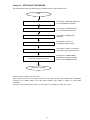
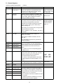
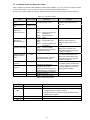
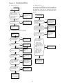
The following flow shows the initial setting-up procedure for the CC-Link interface option.
Start
See Chapter 1 "BEFORE USING THE
CC-Link INTERFACE OPTION."
Acceptance inspection
See Chapter 3 "MOUNTING THE
CC- Link INTERFACE OPTION."
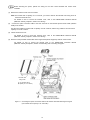
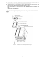
Mount the option
Connect the power cable and CC-Link cable
See Chapter 4 "WIRING AND
CABLING."
Configure the terminating resistor switch (SW5)
See Chapter 2, Section 2.2
"Terminating Resistor Switch."
Turn ON the power to the option and inverter
Configure function codes y98 and o27 to o32
to match the settings in the master
See Chapter 4, Section 4.4 "ON/OFF
Timing of the Option and the Inverter."
See Chapter 5 "CONFIGURING
INVERTER'S FUNCTION CODES
FOR CC-Link COMMUNICATION."
Preparation completed
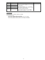
Now the inverter is ready to run via CC-Link.
After confirming that the CC-Link master has been set up, check that the communications link is established
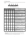
according to the ON/OFF states of the LED status indicators (see Chapter 2, Section 2.3 "LED Status
Indicators").
After the CC-Link master becomes ready, run the sequencer to operate the inverter via CC-Link.
19