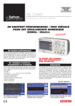
1
S P E C I F I CAT I O N S
SX-METRO
A software package
to meet all your
needs
Products
OX8100
VERTICAL
OX8050
OX8040
OX8062
OX8042
Analog 30MHz
Digital 60Mhz
2 differentials.
2 BNC per channel
1 Mohms/12pF
600V differential
10mV / 200V/div
1 to 2.5
CH1, CH2, -CH2,
ALT, CHOP, ADD,
XY
Analog 20MHz
Digital 40Mhz
2 differentials.
2 BNC per channel
1 Mohms/12pF
600V differential
10mV / 200V/div
1 to 2.5
CH1, CH2, -CH2,
ALT, CHOP, ADD,
XY
OX822
OX863
Front panel
contact software
The OX 863 and the OX 803 can be fitted
with an RS232 interface (option) for
controlling and programming their front
panels via a PC. The software can run from
MS-DOS or Windows. The oscilloscope
can then be remote controlled, using the
front panel displayed on the PC and the
mouse or automation software.
Analysis
Oscilloscope
communications
Analog 100MHz
2
Analog 40MHz
Digital 60MHz
2
Analog 20MHz
Digital 30MHz
2
Number of channels
Input impedance
Maximum input voltage
Sensitivity
Continuous gain adjustment
Operating modes
1 Mohms/15pF
400V
2mV to 5V/div.
1 to 2.5
CH1, CH2, -CH2,
ALT, CHOP, ADD,
XY, MULT, BWL
1 Mohms/25pF
400V
ImV to 20V/div.
1 to 2.5
CH1, CH2, -CH2,
ALT, CHOP, ADD,
XY, MULT
1 Mohms/25pF
400V
ImV to 20V/div.
1 to 2.5
CH1, CH2, -CH2,
ALT, CHOP, ADD,
XY, MULT
Analog 20MHz
Analog 100MHz
Analog 40MHz
Analog 30MHz
2 differentials.
2 BNC per channel
1 Mohms/12pF
600V differential
10mV / 200V/div
1 to 2.5
CH1, CH2, -CH2,
ALT, CHOP, ADD,
XY
2
2
2
1 Mohms/15pF
400 V
2mV to 5V/div.
1 to 2.5
CH1, CH2, -CH2,
ALT, CHOP, ADD,
XY
1 Mohms/25pF
400V
1mV to 20V/div
1 to 2.5
CH1, CH2, -CH2,
ALT, CHOP, ADD,
XY
1 Mohms/25pF
400V
5mV to 20V/div
1 to 2.5
CH1, CH2, ADD,
-CH2, XY, ALT,
CHOP
HORIZONTAL
Archiving
Curves, stored in ASCII files, can be
displayed on the screen and printed, as
and when required, or instrument
configurations can be reloaded.
Source
DIGITAL
FFT: display of signal (CH1 or CH2) and its
Fourier transform (module). Window and
zoom possibilities are provided, together with
a cursor on FFT, enabling the frequency and
amplitude (v or dB) to be measured.
Documentation and
processing
With the SX-METRO software, you can
transfer data (curve or FFT) easily to Excel.
Accordingly, you can insert a signal graph
into a report printed in Word or carry out
additional mathematical calculations on
curve samples.
2
50ns/100ms/div
5ns/200s/div.
4MHz
1 + delay
50ns/100ms/div
5ns/200s/div.
2MHz
1 + delay
50ns/100ms/div
5ns/200s/div.
2MHz
1 + delay
50ns/200ms/div
5ns/200s/div.
2MHz
1 + delay
50ns/200ms/div
5ns/200s/div.
2MHz
1 + delay
50ns/200ms/div
1 + delay
50ns/100ms/div
1
50ns/200ms/div
1
50ns/200ms/div
2MHz
4MHz
2MHz
2MHz
PAL, SECAM, NTSC. PAL, SECAM, NTSC. PAL, SECAM, NTSC. Frame & Line with
With Line counting With Line counting With Line counting true differential
external trigger
CH 1 CH 2 ALT
CH 1 CH 2 ALT
CH 1 CH 2 ALT
CH 1 CH 2 ALT
LINE, EXT
LINE, EXT
LINE, EXT
LINE, EXT
Frame & Line with
true differential
external trigger
CH 1 CH 2 ALT
LINE, EXT
Frame & Line with
true differential
external trigger
CH 1 CH 2 ALT
LINE, EXT
Frame and Line. Frame and Line
Also Trigger on line
number. 1 to 1250
CH 1 CH 2 ALT
CH 1 CH 2 ALT
LINE, EXT
LINE, EXT
100 MS/s
100 MS/s
100 MS/s
100 MS/s
100 MS/s
20 GS/s
2 x (1, 8 or 16 k)
8 bits
Yes
2
20 ns
Yes
Yes
100 MHz
20 GS/s
2 x (1, 8 or 16 k)
8 bits
Yes
2
20 ns
Yes
Yes
60 MHz
20 GS/s
2 x (1, 8 or 16 k)
8 bits
Yes
2
20 ns
Yes
Yes
60 MHz
20 GS/s
2 x (1, 8 or 16 k)
8 bits
Yes
2
20 ns
Yes
Yes
20 MHz
20 GS/s
2 x (1, 8 or 16 k)
8 bits
Yes
2
20 ns
Yes
Yes
20 MHz
SPECIFIC
Yes
1/1, 1/10, 1/100
17 Maths Functions
Vt, 1/t, phase
Yes
1/1, 1/10, 1/100
17 Maths Functions
Vt, 1/t, phase
Yes
1/1, 1/10, 1/100
17 Maths Functions
Vt, 1/t, phase
Yes
1/1, 1/10, 1/100
17 Maths Functions
Vt, 1/t, phase
Yes
Yes
1/1, 1/10, 1/100
17 Maths Functions
Vt, 1/t, phase
SX- METRO software
Minimum configuration
SX-METRO accessories and
Ordering Information
GENERAL
339-6483
Accessories included
The SX-METRO kit contains 1 diskette, 1
PC/oscilloscope serial link lead, 1 25/9pin adaptor,
a gender changer and a user's manual. Furthermore
a free demo of this software is included with every
combined analogue/digital oscilloscope ordered
from RS Components.
Selection of channels to be displayed: the
index pointed shows the selection, CH1 &
CH2 (XY). Other possibilities CH1, CH2 or
CH1 & CH2.
Yes
Yes
Vt, 1/t, phase
CRT 8x10cm
CRT 8x10cm
CRT 8x10cm
CRT 8x10cm
CRT 8x10cm
CRT 8x10cm
CRT 8x10cm
CRT 8x10cm
CRT 8x10cm
RS232 & Centronics RS232 & Centronics RS232 & Centronics RS232 & Centronics RS232 & Centronics RS232 (option)
RS232 (option)
RS232 (option)
(IEEE option)
(IEEE option)
96 to 264V,
96 to 264V,
96 to 264V,
110-230V /
110-230V /
110-230V /
94 to 264Volts
94 to 264Volts
94 to 264Volts
45/440Hz
45/440Hz
50-60Hz
50-60Hz
50-60Hz
48/440Hz
48/440Hz
48/440Hz
450 x 340 x 155mm 450 x 340 x 155mm 450 x 340 x 155mm 450 x 340 x 155mm 450 x 340 x 155mm 450 x 340 x 155mm 450 x 340 x 155mm 450 x 340 x 155mm 450 x 340 x 155mm
7kg
5.5kg
5.5kg
7kg
7kg
6.5kg
6 .0kg
6.3kg
5.5kg
Cat. II 400V
Cat. II, 400V
Cat. II, 400V
Cat.III 300V/
Cat.III 300V/
Cat.III 300V/
Cat. II, 400V
Cat II 400V
Cat II 300V
Cat II 600V
Cat II 600V
Cat II 600V
24 months
24 months
24 months
24 months
24 months
24 months
24 months
24 months
24 months
®
RS Stock No
Yes
1/1, 1/10, 1/100
SPECIFICATIONS
The OX530 & OX8040 are not listed in the RS Catalogue but are available.
For details please contact the RS Quoteline Tel 01536 444101 Fax 01536 405020
SX-METRO acquisition software for OX8020,
OX8042, OX8050, OX8062 and OX8100
CH 1 CH 2 ALT
LINE, EXT
FEATURES
AUTOSET
Probe ratio compensation
Automatic measurements
Measurement cursors
Warranty
Frame and Line
MEMORY
Sampling frequency
(Single Shot)
Equivalent Time Sampling
Record Length
Vertical resolution
FFT and Harmonic analysis
Converters
Glitch Mode
Envelope Mode
Trigger Roll Mode
XY Digital Mode
Display type
Interfaces
(IEEE option)
Power supply
45/440 Hz
Dimensions
Weight
IEC 61010 Safety
SX-METRO
DEFLECTION
Time Base
Sweep speeds (Analog)
Sweep speeds (Digital)
XY mode
TV trigger
This software is used to import curves
stored in the oscilloscope's memory and
"picture" files or to load a configuration
into the instrument, via the RS232 or IEEE
interfaces.
Model
1kHz 1Vpk-pk signal
Analogue/Digital
Analogue and
Differential
Oscilloscopes
TRIGGERING
SX-METRO enables you to display curves
(definable display window, scale, graticule
and cursor options, ...) and to carry our
mathematical routines such as the FFT of
the displayed signal (windowing and zoom
of result, Y scale of FFT in volts or dB,
measurements by markers).
• MS-DOS version 3.1 or higher
• Microsoft Windows 3.1, Windows
95/98, Windows NT,...
• PC or 80386-compatible computer or
higher and clock speed of at least
25MHz. (80486 33MHz
recommended)
• VGA resolution (or higher)
• Math coprocessor
• At least 4Mb RAM, 8Mb
recommended
• Approx. 30Mb of free hard disk
capacity
OX530
DEFLECTION
Bandwidth
Component Tester
SX-METRO Software
OX803
RS shall not be under any liability for damage, loss, expense, loss of revenue or any consequential
or indirect loss resulting from advice or information given in this manufacturer's leaflet. Please refer
to the current RS Catalogue for prices and conditions of sale and servicing.
RS Components Limited
P.O. Box 99, Corby
Northamptonshire NN17 9RS
Tel 01536 201201 Fax 01536 201501
On-line ordering: http://rswww.com
and RS are registered trademarks of RS Components Limited
an Electrocomponents Company
Your complete Calibration and Repair service
ensures your oscilloscope meets your precise
specification or calibration requirements.
SPOINTCal complies with BS EN 30012-1:1994
NAMAS Cal incorporates BS EN 30012-1: 1994
plus the auditing of the quality of the physical
measurements made.
Tel 01536 405545 Fax 01536 401590
Chauvin Arnoux (UK) Ltd
Waldeck House, Waldeck Road
Maidenhead SL6 8BR
Tel (01628) 788888
Fax (01628) 628099
Metrix oscilloscopes are designed to meet all your signal
measurement and analysis needs, for production,
laboratory, R&D or professional training applications.
Our Differential oscilloscopes means that you no longer
require the use of an additional voltage probe.
Our Combined oscilloscopes give you the advantage of
digital and analogue systems, enabling you to display a
signal in real time, in analogue mode, and view events
prior to triggering.
A full choice of
Analogue models
from 30 to
100MHz
Combined oscilloscopes
provide the power of
Digital technology plus
Analogue mode
OX 8100 OX 8050 OX 8040
Analogue plus digital
processing
The power of combined digital processing
enables you to display and store events
prior to triggering and therefore analyse
the causes of a phenomena, over a wide
range of scan speeds and input
frequencies. With a Combined Metrix
oscilloscope, you can display very slow
phenomena (temperature variations, battery
charges, very low frequencies,....). Finally,
after acquisition, you can analyse and
compare the recorded data (zoom,
automatic measurements,....)
A wide range
of digital functions
As well as their 5 cursors, the Combined
oscilloscopes offer up to 17 automatic
measurements. Their "GLITCH" mode, for
capturing parasites, and "ENVELOPE"
mode, for storing the minimum and
maximum values of several successive
acquisition operations, allow a large
number of events to be displayed. Lastly,
because RS 232 and Centronics links are
standard features on most models, users
can take advantage of the possibilities
offered by digital techniques: analysis and
processing on PC by the SX-METRO
software, direct printout of the screen on a
printer, etc.
Print quality equal
to display quality
Standard delivery includes FFT
and harmonics analysis
All digital models in the range include the
FFT function, for studying the frequency
breakdown of the signal, and harmonics
analysis, both as standard features. In FFT
mode, the cursor follows all the signal
counts, each time indicating the amplitude
(in Volts or dB) and the frequency. In
harmonics mode, the cursor automatically
jumps from one harmonic to the next,
indicating the number of the harmonic, its
amplitude as a percentage of the
fundamental and its frequency. This
representation of the harmonics is richer
than a conventional bar display.
The sampling concept quickly demonstrates
its limits when the signal includes steep rises
and falls. The solution currently used
involves interpolating dots between them
(METRIX EADJ dot-join function). Although
this process has been around for some
time, its extension to printing is much rarer.
Unlike many oscilloscopes, the combined
oscilloscopes offer the same quality of
representation for display and printing
(subject to the performance of your printer).
Representation of rapid rises and falls on
screen without the EADJ function.
The FFT and harmonics analysis displays
particularly distinctive because of the way the
cursor moves and the nature of the information
indicated on the screen
Same signal with the EADJ function.
Combined Analogue/Digital
Scopes Ordering Information
Model
Bandwidth
RS Stock No
OX8050
+NAMAS Cal
+SPoint Cal
50MHz
339-7212
343-2488
343-2472
OX8100
+NAMAS Cal
+SPoint Cal
100MHz
339-7228
343-2501
343-2494
Printout of the same
signal with the EADJ
function.
Differential input
oscilloscopes
offer a single,
global solution
OX 863 OX 803 OX 530
17 automatic
measurements
tr
tf
F
T
W+
WVeff
Vmoy
Vamp
Vbas
Vh
Vpp
Vmax
DC+
DCϕ
up time
down time
frequency
period
positive pulse width
negative pulse width
RMS voltage
average voltage
amplitude
low voltage
high voltage
peak to peak voltage
max voltage
positive duty ratio
negative duty ratio
phase shift
Programming
The Metrix combined oscilloscopes are
fully programmable, in compliance with the
SCPI (Standard Commands for
Programmable Instruments) standard. They
have RS232 interfaces for printing and
remote control. You can thus take full use
of all the analysis, documentation and
presentation tools available under
LabView* and LabWindows CVI*. These
oscilloscopes have a standard digital
automatic peripheral recognition link, with
an RS232 or Centronics connection. You
can thus send screen dumps directly to a
printer. The SX-METRO software package
enables you to control instruments,
archiving, documentation and result
processing. *LabWindows CVI and
Labview are registered trademarks of
National Instruments.
OX 8062 OX 8042 OX 822
Advantages of
analogue mode
Screen display
of parameters and cursors
The only genuine protection
against dangerous voltages
IEC 61010, Cat.III, 300 V Cat.II,
600 V, what could be better?
Analogue processing enables signals to be
displayed in real time, without delay
resulting from analogue/digital conversion
and storage.
The entire signal is represented, rather than
a series of points, without any danger of
misinterpretation. In addition, in analogue
mode, virtually all trigger elements are
represented. Finally, the Autoset and
delayed trigger functions enable signals to
be synchronised without difficulty.
The OX 863 oscilloscope has a Readout
function, for displaying: vertical and
horizontal offset coefficients, the triggering
point and its slope, the TV standard or line,
the probe coefficient or the measuring
cursors.
In today's world, nobody can ignore safety
any more. But are you always sure that the
voltage measured is earthed? Do you
always have a single reference potential for
the 2 channels? If you look objectively at
the various cases of measurement on site,
whether in electronics or the
electrotechnical field, you will see that it is
often necessary to set up a costly and
complex assembly. With METRIX's
differential-input oscilloscopes there is no
need to use accessories to observe the
signals superimposed on the mains signal
or to analyse the command voltage and the
output from any circuit at the same time,
with a common mode voltage of up to
600V.
The OX 8062, OX 8042 and OX 822
oscilloscopes can be used in the laboratory
or on site, even in difficult industrial
environments, as shown by their installation
category...
Ease of Use
All Metrix oscilloscopes have the same
appearance and handling as Analogue
oscilloscopes, no specific training is
necessary. In addition, they have an
AUTOSET function, which enables you to
automatically obtain a correct
representation of the signal, with readout of
parameters on the screen.
Counting of
video lines
Each model has a TV trigger mode,
enabling all the lines of a video picture to
be displayed. The OX 863 also has a
video line counting mode. This trigger
mode is used to display a specific line,
chosen by the user from the TV norm (252 625 lines) or a specific norm ( up to 1255
lines). This line can be analysed via the
second time base.
Change the mode
as you want
In differential mode, one BNC connector
corresponds to the + terminal and another to
the - terminal. In conventional mode: CH1and CH2- are inhibited
With no danger, it is possible to switch from
one operating mode to the other at any
time simply by pressing a button. This
flexibility will be particularly appreciated
for electronic applications that use miniature
probes.
Up to 200V/div.
without accessories
With a conventional oscilloscope
Only METRIX oscilloscopes are suitable for
such a wide range of uses.
Whether the signal amplitude is high or
low, the OX 8062, OX 8042 and OX 822
offer a sufficiently wide dynamic range
(from 10 mV/div. to 200 V/div.) for
measurement without probes. More savings
and more flexible use!
Differential Input Scopes
Ordering Information
With a differential oscilloscope
Model
Analogue Scopes
Ordering Information
Model
The AUTOSETfunction provides a correct
representation of the signal, simply and
automatically.
Bandwidth
RS Stock No
OX803
+NAMAS Cal
+SPoint Cal
40MHz
262-8852
262-9653
262-9669
OX863
+NAMAS Cal
+SPoint Cal
100MHz
262-8868
262-9940
262-9956
Each channel operates independently in
differential or conventional mode. All you have
to do to choose the mode is press a key.
Example of use of a differential oscilloscope
Bandwidth
RS Stock No
Combined Analogue/Digital
OX8042
40MHz
339-6461
+NAMAS Cal
343-2545
+SPoint Cal
343-2539
OX8062
+NAMAS Cal
+SPoint Cal
OX822
+NAMAS Cal
+SPoint Cal
60MHz
Analogue only
20MHz
339-6449
343-2523
343-2517
339-6477
343-2573
343-2551