1
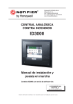
ID3000
997-505-000-3, Issue 3 October 2007
operating
manual
ID3000 Series Operating Manual
Contents
Quick Contents Reference by
Section
i
997-505-000-3, Issue 3
October 2007
ID3000 Series Operating Manual
Contents
1
Introduction
1.1
Associated Documents
1
1.2
Cleaning
1
2
Panel Controls and Indicators
Main Panel
2
2.2
Zone LED Panels
5
Automatic Alarms - What to Do
6
3.1
Fire Alarms
7
3.2
Pre-alarms
8
3.3
Fault Alarms
9
4
Contents
2
2.1
3
How To:
10
4.1
Evacuate (and End Delays)
10
4.2
Mute Buzzer
11
4.3
Silence/Resound Sounders
12
4.4
Reset the Panel
13
4.5
Disable/Enable Devices and Zones
(Quick Method)
14
4.5.1 From Fire Tab
14
4.5.2 From Pre-alarm Tab
15
4.5.3 From Disable Tab
15
4.6
Discontinue a Walk Test (Quick Method)
16
4.7
Select Day or Night Mode
17
4.8
Disable a Fire Output
17
4.9
Using Other Panel Controls
17
5
The Display - Tabs, Events and
Menus
5.1
997-505-000-3, Issue 3
October 2007
1
18
Introduction
18
5.1.1 Status:NORMAL
18
5.1.2 Tabs
18
5.1.3 Events
18
5.1.4 Menus
18
5.2
Tabs
19
5.3
Event Displays
20
5.3.1 Extinguishing System Display
20
5.3.2 Fire Alarm Event Display
22
ii
ID3000 Series Operating Manual
6
23
5.3.4 Technical Alarm Display
23
5.3.5 Fault Event Display
24
5.3.6 Disable Event Display
25
5.3.7 Test Event Display
26
5.3.8 Evacuate Event Display
27
5.3.9 Auxiliary Event Display
27
Menu Displays
28
5.4.1 To Display the User Menu
28
5.4.2 To Navigate Through the Menus
29
5.4.3 Menu Structure
30
Test Menu
6.1
31
Introduction
31
6.1.1 Indications
31
6.2
Zone Walk Test
32
6.3
Control Output Tests
33
6.4
Lamp Test
34
6.4.1 Lamps Test in Sequence
34
6.4.2 All Lamps Lit
35
6.5
Sensor Automatic Test
36
6.6
Replace VIEW Sensor
36
Disable/Enable Menu
37
7
7.1
Introduction
37
7.1.1 Indications
37
Disable/Enable Inputs
38
7.2.1 Disable All Input Devices
38
7.2.2 Disable All Sensors
39
7.2.7 Enable All Input Devices
39
Disable/Enable Outputs
40
7.3.1 Disable/Enable All Sounders
40
7.3.2 Disable/Enable All Control Outputs
41
Individual Device
42
7.4.1 Sensor
42
7.4.2 Module
43
7.4.3 Sounder/Relay Circuit
43
7.4.4 Virtual Points
44
7.5
Delayed Sounders Mode
44
7.6
Network Disable and Enable
45
7.6.1 Input Zone
45
7.2
7.3
7.4
iii
997-505-000-3, Issue 3
October 2007
Contents
5.4
5.3.3 Pre-alarm Event Display
ID3000 Series Operating Manual
7.6.2 Device
46
7.7
Disable/Enable via Remote Switch
47
7.8
Time-of-Day Control and Override
47
Contents
8
Log/Display/Print Menu
8.1
Introduction
48
8.2
Log/Display Device Data
49
8.2.1 Analog Graphical Display
51
8.3
Print Current Device Data
53
8.4
Display/Re-Print Event Log
54
8.5
Printer Control Modes
55
8.5.1 Mains Failure
55
9
Setting the Clock
56
10
Other User Menu Options
57
10.1 Alarm Count
57
10.2 Enter Level 3 Passcode/Configuration
57
10.3 Set Language
57
11
Non-latched Input Operation
Appendix 1 - Log Book
997-505-000-3, Issue 3
October 2007
48
iv
58
A1 - 1
ID3000 Series Operating Manual
1
Introduction
This manual contains operating instructions for
the ID3000 Series of Intelligent Fire Detection
Panels. Users of this manual are assumed to
be working with a panel that has already been
installed and configured appropriately for the
area under its supervision.
In some installations, panels may be
connected together in a network of up to eight
panels plus repeaters making a total of up to
32 stations.
ID3000 Series panels may be connected to
up to eight loops of addressable analogue
sensors and modules. Each loop has the
capacity for up to 99 analogue sensors plus
up to 99 modules.
Illustration shows a panel with two extension chassis,
one with 64 zone LEDs and a printer, and the other
blank.
1.1 Associated Documents
This manual does not cover details on the
installation or configuration of ID3000 Series
panels. For information on these topics, refer
to the ID3000 Series Installation and
Commissioning Manual (997-274-XXX) and
the ID3000 Series Panel Configuration Manual
(997-506-XXX) respectively.
Panel software upgrade procedures and panel
software compatibility issues are described in
the ID3000 Series Panel Configuration Manual
(997-506-XXX).
Note: ‘XXX’ is the country code for the manual
(000 for the UK).
1.2 Cleaning
The panel case may be cleaned periodically
by wiping with a soft, damp lint-free cloth. Do
not use any solvents.
1
997-505-000-3, Issue 3
October 2007
Introduction
The ID3000 Series panel always has a main
chassis, which includes all of the panel controls
and indicators except for zone LEDs. The
panel may also have up to two optional
extension chassis, each of which may house
zone LEDs for either 64 or 128 zones (a panel
can have a maximum of 255 zones). All the
control and operation functions described in
this manual can be carried out using the
pushbuttons on the front of the main chassis.
ID3000 Series Operating Manual
2
Panel Controls and Indicators
2.1 Main Panel
This section provides an overview of the user
interface controls and indicators, and
references the section(s) of this manual that
provide more detailed information.
MUTE
BUZZER
DAY MODE
EXTEND
DELAY
END DELAY/
EVACUATE
FIRE O/P
DISABLE
SILENCE/
RESOUND
CHANGE
TABS
RESET
ZONES IN
ALARM
7
8
9
4
5
6
1
2
3
Panel Controls and Indicators
0
FIRE
FAULT
DISABLEMENT
PRE-ALARM
DAY MODE
SYSTEM FAULT
DELAYS ACTIVE
SOUNDER FAULT/DISABLED
TECHNICAL ALARM
TEST
POWER
FIRE O/P FAULT/DISABLED
FIRE O/P ACTIVE
PRIMARY INDICATOR
LCD graphics display - refer to Section 5.
Status:NORMAL
Mon 20-Nov-2006 11:20:07
PUSHBUTTONS
Silences the panel internal buzzer, and accepts
an alarm. Refer to Section 4.2.
If DAY MODE is configured, introduces a
second stage delay if an alarm occurs while
DAY MODE is active. Refer to Section 4.7.
If any delays are active, first operation cancels
the delays, second operation sounds all
sounders so-configured. If no delays are
active, sounds all sounder so-configured.
Refer to Section 4.1.
Stops and restarts the sounders. Refer to
Section 4.3.
Restores normal operating status when all
alarm conditions have been removed. Refer
to Section 4.4.
997-505-000-3, Issue 3
October 2007
2
ID3000 Series Operating Manual
Toggles between day and night modes, if they
are configured. Refer to Section 4.7.
The Fire relay output (and the Fire Output, if
sounder circuit 1 is configured as such) is
disabled. Refer to Section 4.8.
Scrolls through the tabbed displays. Also used
to display the User Menu when the panel status
is Normal. Refer to Sections 5.2 and 5.3.
Displays fire alarm information. If there is more
than one zone in fire event, scrolls through
these zones. Refer to Section 5.2 and 5.3.
KEYPAD
Used to move around the LCD menus. Press
to advance the printer paper
and hold
(maximum of 20 lines are advanced for a
single press of this pushbutton).
Used to select quick methods of dis/
enablement (Section 4.5) and walk test
cancellation (Section 4.6), to navigate through
the menus (Section 5.4.2) and to control the
event log display (Section 8.4). Also used
during configuration (refer to the Panel
Configuration Manual 997-506-XXX).
Used to select items and enter data on LCD.
Used to accept an item or state on the LCD.
Used to cancel an item or state on the LCD.
Setting the keyswitch to the right has the same
effect as entering an access 2 passcode. Set
it to the centre to de-select access level 2.
3
997-505-000-3, Issue 3
October 2007
Panel Controls and Indicators
Spare - Not used.
ID3000 Series Operating Manual
LEDs
A fire condition exists.
A fault condition exists.
A pre-alarm condition exists.
The system has failed.
Sounders have failed or been disabled.
The Fire relay is disabled, or the Fire output (if
configured) is disabled or has a fault.
Panel Controls and Indicators
The Fire relay (and the Fire output if
configured) is active.
One or more devices are disabled.
A test condition has been entered.
System power (mains or battery) is available.
The DAY MODE has been entered.
Programmed delays are in effect.
TECHNICAL ALARM
Technical Alarm device activated.
Spare (2 off) - Not used.
997-505-000-3, Issue 3
October 2007
4
ID3000 Series Operating Manual
2.2 Zone LED Panels
Two configurations of optional zone LED
chassis may be fitted, each with up to two
chassis, as follows:
a. 64 zone LEDs per chassis, i.e. 128 zone
LEDs in total. This configuration allows a
printer to be fitted.
64 zone configuration:
ZONE
LEDs
1-64
(chassis 1).
ZONE LEDs 65-128
(chassis 2).
128 zone configuration:
ZONE LEDs 1-128
(chassis 1).
ZONE LEDs 129-256
(chassis 2). Maximum of
255 zones per panel.
ZONE FIRE LEDs indicate which zones are in a fire
condition.
ZONE FAULT/DISABLE/TEST LEDs indicate which
zones are in fault, disablement or test conditions.
5
997-505-000-3, Issue 3
October 2007
Panel Controls and Indicators
b. 128 zone LEDs per chassis, i.e. 256 zone
LEDs in total (maximum 255 zones).
ID3000 Series Operating Manual
3
Automatic Alarms - what to
do
The following assumes that either:
a. The access passcode 2 is active (see
Section 5.4.1), or
Automatic Alarms - What to do
b. That the panel keyswitch is operated
(turned to the right) to allow the pushbuttons
to be used without the access 2 passcode.
997-505-000-3, Issue 3
October 2007
6
ID3000 Series Operating Manual
Automatic panel actions - If the system
detects a fire alarm, the panel always does the
following automatically:
a. Operates the internal (high-pitched) buzzer.
b. Flashes the red FIRE LED and numbered
red FIRE ZONE LED (if fitted).
c. Displays and prints (if printer is installed and
enabled) information about the event.
Displays a FIRE tab on the LCD.
d. Operates the fire transfer output(s), for fire
brigade alert.
e. Operates the sounder circuits and remote
Control Modules according to the panel’s
configuration, as set during commissioning.
f. If any delayed sounders are incorporated in
the panel’s configuration, the DISABLEMENT
LED remains lit steadily and the DELAYS
ACTIVE LED changes state from steady to
flashing mode.
Note: When the timer has run out and the
sounders activated, the DELAYS ACTIVE
LED extinguishes if there are no other
sounder disablements on the system.
When the panel is reset the DELAYS
ACTIVE and DISABLEMENT LEDs light
steadily again.
g. Any pre-alarm indications are suppressed
when the panel enters the FIRE alarm state.
In the FIRE alarm state the panel will give
no further indication of pre-alarm
occurrences. Point information on prealarms may be accessed at the LCD but is
suppressed by the fire event information.
If the panel is configured with
extendable sounder delays: To
extend the delay, operate
EXTEND
DELAY.
This
pushbutton is also used with
Day Mode (Section 4.7).
FLASHING LEDs
BECOME STEADY
Recommended operator actions:
1 Press the MUTE BUZZER pushbutton.
Flashing LEDs change to steady operation.
The internal buzzer changes to intermittent
operation (once every 12 seconds).
2 Follow prescribed instructions for
evacuation of premises, notification of Fire
Brigade and investigation of source of Fire.
3 If additional sounder operations are required
to achieve a complete and immediate
evacuation of the premises, press the END
DELAY/EVACUATE pushbutton twice (first
operation cancels any active delays).
4 When evacuation of premises is achieved,
or at the direction of an authorised person,
the Alarm sounders may be silenced by
pressing the SILENCE/RESOUND pushbutton.
Any delayed operations for which the timer
has not yet expired are also cancelled by
pressing SILENCE/RESOUND, if configured.
BUZZER
BECOMES
INTERMITTENT
1
3
FIRST OPERATION
4
7
997-505-000-3, Issue 3
October 2007
Automatic Alarms - What to do
3.1 Fire Alarms
THE FOLLOWING SOUND OR LIGHT:
ID3000 Series Operating Manual
5 To re-start sounders after having pressed
SILENCE/RESOUND, press the SILENCE/
RESOUND pushbutton again.
SECOND OPERATION
Automatic Alarms - What to do
5
Status:NORMAL
6 When the cause of alarm has been
removed and call points and input devices
have been locally reset, the system may
be returned to NORMAL by pressing the
RESET pushbutton.
Mon 20-Nov-2006 11:20:07
6
3.2 Pre-alarms
This is the condition when one or more input
devices has signalled a PRE-ALARM to the
panel - i.e. a reading which is higher than
normal but not yet at the FIRE level.
THE FOLLOWING SOUND OR LIGHT:
Automatic panel actions:
a. Steady operation of the internal (highpitched) buzzer.
b. Flashing of amber PRE-ALARM LED.
c. Operation of those programmed control
outputs which are associated with prealarm events (if there are any specified in
the programmed panel configuration).
d. Display and printing (if printer is installed
and enabled) of the event. Displays a
PRE-ALARM tab on the LCD.
Recommended operator actions:
1 Press the MUTE BUZZER pushbutton. The
internal buzzer changes to intermittent
operation (once every 2 minutes). Flashing
PRE-ALARM lamp changes to steady
operation.
2 Check condition of detector indicated and
check area for possible fire. If the cause
cannot be determined notify authorised
Servicing company.
3 When cause of pre-alarm has been
cleared, press RESET pushbutton.
997-505-000-3, Issue 3
October 2007
8
ID3000 Series Operating Manual
3.3 Fault Alarms
Automatic panel actions - If the system
identifies a fault, the panel always does the
following automatically:
THE FOLLOWING SOUND OR LIGHT:
a. Operates the internal FAULT buzzer.
b. Flashes one or more amber FAULT LEDs,
including numbered amber ZONE Fault
LED(s) if appropriate.
d. Displays and prints (if printer is installed and
enabled) information about the event.
Displays a FAULT tab on the LCD.
Note: For a sensor fault, only the point of origin
or a brief reference appears on the text
display.
e. Operates the fault transfer relay (for
automatic alert to a service centre).
Recommended operator actions:
1 Press the MUTE BUZZER pushbutton. The
internal fault buzzer changes to intermittent
operation (once every 2 minutes).
2 If the fault relates to a specific sensor or
module, investigate device to see if cause
of fault is immediately apparent and can
be corrected.
3 In all other cases, note full description of
fault and notify the authorised Servicing
company.
4 When cause of fault has been cleared,
press the RESET pushbutton.
9
997-505-000-3, Issue 3
October 2007
Automatic Alarms - What to do
c. Operates any control outputs which are
associated in the pre-programmed panel
configuration with fault events.
ID3000 Series Operating Manual
4
How to
All pushbuttons described in this section
except END DELAY/EVACUATE require entry
of an access 2 passcode, or the keyswitch set
appropriately. If the passcode is not currently
active, the LCD screen displays a request for
it (see Section 5.4.1). Enter the passcode and
then press the
pushbutton.
IF
Note: MUTE BUZZER and EXTEND DELAYS
may be configured in the panel to
operate at access level 1.
IS FLASHING AMBER, THEN FIRST
4.1 Evacuate (and End Delays)
If the DELAYS ACTIVE LED is flashing (panel
in alarm) press the END DELAY/EVACUATE
pushbutton once to end the delays.
This pushbutton also ends DAY MODE
delays (see Section 4.7).
OTHERWISE (LIT STEADY OR OFF), JUST
How to
With no delays active (DELAYS ACTIVE LED
either lit steady if delays are configured but
not active, or not lit if delays have timed out or
have ended after first operation of the END
DELAY/EVACUATE pushbutton):
1 Press the END DELAY/EVACUATE
pushbutton.
2 If at level 1, enter the access 2 passcode
followed by
. If at level 2, just press
to cause sounders and other devices to
operate, if they are configured to do so.
IF AT LEVEL 1, ENTER THE LEVEL 2 PASSCODE.
IF ALREADY AT LEVEL 2, THE DISPLAY IS
DIFFERENT:
IN EITHER CASE:
If END DELAY/EVACUATE is pressed while
the SILENCE/RESOUND mode is set to
SILENCE, first the sounders are re-activated,
then any additional actions occur as required
by the evacuation strategy configured in the
panel.
Note: The evacuation strategy could be
completely different to the Fire alarm
actions configured in the panel.
997-505-000-3, Issue 3
October 2007
10
ID3000 Series Operating Manual
4.2 Mute Buzzer
After an alarm or fault has occurred, press the
MUTE BUZZER pushbutton to:
FLASHING, OR
a. Accept the alarm or fault. The flashing FIRE
or FAULT LEDs light steady.
FLASHING
b. Switch either the FIRE or FAULT internal
buzzer from continuous to intermittent
operation:
CONTINUOUS
FIRE buzzer at 12 seconds interval.
FAULT buzzer at 2 minutes interval.
If both buzzers are sounding, the FIRE buzzer
operates intermittently and the FAULT buzzer
is silenced.
How to
STEADY, OR
STEADY
INTERMITTENT
WHEN ALARM CONDITION IS CLEARED:
This mode of operation then continues until the
system is RESET (FIRE and FAULT conditions
latch).
OFF
11
997-505-000-3, Issue 3
October 2007
ID3000 Series Operating Manual
4.3 Silence/Resound Sounders
The term ‘silence’, as used throughout this
manual, describes a temporary state the panel
enters whenever the SILENCE/RESOUND
pushbutton is pressed to stop the sounders
operating. While the panel is in this state, a
new fire alarm, or operation of the END
DELAY/EVACUATE pushbutton, will re-sound
all previously-silenced sounders.
OR
(SEE SECTION 4.1)
To cancel all sounder output delays and all
sounder outputs which are operating as a
result of a FIRE alarm or an EVACUATE
operation:
1 Press
the
SILENCE/RESOUND
pushbutton. The following are not switched
off by this operation:
a. The internal FIRE buzzer (except in the
case detailed below).
How to
b. Any external Control Modules that
have been programmed not to be
silenced by SILENCE/RESOUND.
SILENCE
TO RE-SOUND FROM FIRE ONLY
(DOES NOT WORK FROM EVACUATE)
2 To start the sounders again in the same
pattern as they were previously operating,
press
the
SILENCE/RESOUND
pushbutton.
Note: SILENCE/RESOUND works for a fire
condition only, not for an operation of
the END DELAY/EVACUATE pushbutton.
Note: When the sounders are restarted, the
internal fire sounder will also change
back to steady mode of operation and
you may have to press MUTE BUZZER
again.
997-505-000-3, Issue 3
October 2007
12
ID3000 Series Operating Manual
4.4 Reset the Panel
To reset the system completely (except after
an EVACUATE operation), press the RESET
pushbutton. The following occurs:
a. All FIRE, PRE-ALARM and FAULT
LEDs are switched off.
ALL OFF
c. A SYSTEM RESET message is
displayed briefly.
d. The status returns to NORMAL.
Status:NORMAL
e. Some internal tests are carried out:
they will be completed within a few
seconds.
Mon 20-Nov-2006 11:20:07
External Control Modules will be switched off,
even if they are programmed to not be silenced
by SILENCE/RESOUND.
If an Alarm, Pre-Alarm or Fault is still present
when RESET is pressed, it will be reported as
if it were a completely new event with
appropriate annunciation.
13
997-505-000-3, Issue 3
October 2007
How to
b. All sounders cease to operate (either
steadily or intermittently).
ID3000 Series Operating Manual
4.5 Disable/Enable Devices and Zones
(Quick Method)
This allows a device or zone to be:
a. Disabled quickly if the Fire tab is current,
and then re-enabled.
b. Disabled quickly if the Pre-alarm tab is
current, and re-enabled. Devices only.
c. Enabled quickly if the Disable tab is current,
or fully-disable a partially-disabled zone.
4.5.1 From Fire Tab
Device
The example shows how to disable an
individual device when the Fire tab is displayed.
This method also applies to Virtual Input Points
(ID2net only: points may be on remote panels).
USE ONCE, ENTER
PASSCODE, THEN
REPEATED
USE UNTIL
How to
Further details about the Fire tab are given in
Section 5.3.1, Fire Alarm Event Display.
Networked systems only - the current
enablement status of a device on a remote
panel is unknown to the local panel, so the
options shown below are given instead of the
prompt shown at left.
Repeating this procedure displays the option
to enable the disabled device.
Zone
Alternatively, press
when DISABLE THIS
ZONE is highlighted, then select either ALL
SENSORS or ALL INPUTS (this choice is not
provided for remote networked panels). A
confirmation prompt is then displayed.
Repeating this procedure displays the option
to enable the disabled zone.
997-505-000-3, Issue 3
October 2007
14
ID3000 Series Operating Manual
4.5.2 From Pre-alarm Tab
The example shows how to disable an
individual device when the Pre-alarm tab is
displayed. The procedure is similar to that for
Fire but:
a. There is no DISABLE THIS DEVICE to
highlight; just press
device is displayed.
while the required
b. There is no ZONE option.
Access level 2 passcode is required.
Further details about the Pre-alarm tab are
given in Section 5.3.2 Pre-alarm Event
Display.
Repeating this procedure displays the option
to enable the disabled device.
4.5.3 From Disable Tab
The example shows how to enable a disabled
zone when the Disable tab is displayed.
Individual devices can also be enabled (first
display the appropriate device). The procedure
is similar to that for Pre-alarm.
Access level 2 passcode is required.
Further details about the Disable tab are given
in Section 5.3.4 Disable Event Display.
The use of the menu system to disable and
enable devices and zones is described in
Section 7, Disable/Enable Menu.
This procedure is not available for zones on
remote networked panels.
Status:NORMAL
Mon 20-Nov-2006 11:20:07
This example shows a partially-disabled zone.
This can be fully disabled for either ALL
SENSORS or ALL INPUTS (there is no quick
method to disable outputs, nor is there one to
enable a partially-disabled zone).
15
997-505-000-3, Issue 3
October 2007
How to
Networked systems - Differences described
for Fire at networked panels also apply to Prealarm.
ID3000 Series Operating Manual
4.6 Discontinue a Walk Test (Quick
Method)
PANEL 2 ZONE 8 IN TEST
Inputs: Tested 3; Not Tested 10
Panel 2: Security Office
L2 S13
Main corridor
Sensor outside room 5
ION
Test User
Tue 27-Jul-2004 11:20:07
The example shows how to cancel a walk test
when the Test tab is present.
Access level 2 passcode is required.
The left arrow only applies if there is more than
one zone in test. The Panel name is only given
if the panel is on a network and using local
(panel) zone numbering.
CANCEL TEST MODE: ALL ZONES
( /X)?
Test User
When the ‘
‘ pushbutton is operated:
a. If multiple zones are in test the prompt
indicates that all zones will be cancelled. It
is not possible to choose zone(s) for
cancellation of the test.
Tue 27-Jul-2004 11:20:07
OR, IF ONLY ONE ZONE IN TEST:
b. If only one zone is in test, this zone is
explicitly named in the prompt.
CANCEL TEST MODE: PANEL 2 ZONE 8
( /X)?
Further details about the Test tab are given in
Section 5.3.5 Test Event Display.
Tue 27-Jul-2004 11:20:07
The use of the menu system to start and stop
the zone walk test is described in Section 6.2
Zone Walk Test.
How to
Test User
997-505-000-3, Issue 3
October 2007
16
ID3000 Series Operating Manual
4.7 Select Day or Night Mode
IF DAY MODE IS SELECTED:
IS LIT STEADILY. IF THERE IS AN ALARM IT
FLASHES DURING THE DELAY. TO EXTEND
THE DELAY, PRESS:
Note: If EXTEND DELAY is operated when no
delays are active the message ‘There
are no delays running which can be
extended’ is displayed.
b. NIGHT - There are no delays on the fire
output(s). The DAY MODE LED is not lit in
this mode.
Note: Although any outputs can be configured
with delays, only the fire output(s) are
affected by the Day Mode delays.
Selection of Day Mode will also reduce the sensitivity
of sensors configured for this option (includes setting
Multi-criteria sensors into thermal-only mode).
4.8 Disable a Fire Output
If any of the panel internal Sounder/Relay
circuits or the Fire VFCO Relay have been
configured as Remote Fire Outputs, operation
of the FIRE O/P DISABLE pushbutton disables
these outputs.
Press the FIRE O/P DISABLE pushbutton a
second time to re-enable the Remote Fire
Outputs.
Note: The configuration procedure is given in the
ID3000 Series Panel Configuration Manual,
997-506-XXX Section 11.2.17.
4.9 Using Other Panel Controls
Refer to Section 5 for use of the CHANGE
TABS and ZONES IN ALARM pushbuttons,
and of the numeric keypad and cursor keys.
17
997-505-000-3, Issue 3
October 2007
How to
This pushbutton toggles between Day Mode
and Night Mode for the fire output(s), providing
the function is configured. If it is not configured,
the message ‘Day/Night Mode not
implemented on this system’ is displayed.
Note: The panel may also be configured to
enter Day Mode automatically at
specified times of day.
The modes have the following effects:
a. DAY - The DAY MODE LED is lit steadily and a
two-stage investigation time delay is configured
on the fire output(s). If an alarm occurs, the DAY
MODE LED flashes, indicating that the first stage
investigation delay is active. The second stage
investigation delay is initiated by pressing the
EXTEND DELAY pushbutton during the firststage delay time (while the DAY MODE LED is
flashing) - its duration takes into account the
time already elapsed for the first stage. When
the delay(s) expire, the fire output(s) are
activated and the DAY MODE LED extinguishes
(until the panel is reset).
ID3000 Series Operating Manual
5
The Display - Tabs, Events
and Menus
5.1 Introduction
5.1.1 Status: NORMAL
The Status: NORMAL display appears when:
The Display - Tabs, Events and Menus
a. No alarm or test conditions exist, and
b. No menus are being accessed.
Status:NORMAL
Mon 20-Nov-2006 11:20:07
Other NORMAL indications:
POWER LED (green)
Other LEDs
Internal buzzers
Internal sounder circuits
FIRE, FAULT relays
Control modules
ON
OFF
OFF
OFF
OFF
OFF (unless operated by
an auxiliary action)
The built-in LED indicators on all sensors and modules should
either give short pulses or be off altogether.
5.1.2 Tabs
When conditions other than Status: NORMAL
exist, the LCD displays event data. More than
one type of data may be available for display
at any one time (eg, Fire Alarms, Faults, Menus
etc.). When this occurs, the types of data
available are identified by tabs at the bottom
of the display.
5.1.3 Events
Fire Alarms, Pre-alarms, Faults, Disablements,
Tests, Evacuate mode, and Auxiliary input
activations are shown on Event displays. A
Fault event display is shown. On networked
panels the ‘Location’ text is replaced by the
panel type (e.g. Master, Slave 1 etc).
5.1.4 Menus
Menus are arranged in a heirarchy, the top of
which is the User Menu from which other
menus are accessed.
997-505-000-3, Issue 3
October 2007
18
ID3000 Series Operating Manual
5.2 Tabs
When tabs are displayed, use the CHANGE
TABS pushbutton to scroll through them and
display the corresponding data.
EXTINGUISHING (if about to release;
otherwise priority is below FIRE)
FIRE
TECH. ALARM
PRE-ALARM
FAULT
DISABLE
TEST
EVACUATE
AUX
MAINT
USER (at access level 2)
The tabs are displayed in this order from left to
right. All the tabs display events except for the
USER tab, which displays menus. The current
tab is that without a line above it.
To the right of the tabs is a display of the current
day, date and time. If there is insufficient room
to display all the tabs, the day/date/time display
is shortened, the minimum being a display of
hours and minutes.
Note: If there is still insufficient room to display
all the tabs, the ones at the right (those
with lowest priority) are omitted.
Use ZONES IN ALARM to go directly to the
FIRE tab without scrolling through the other
tabs. If there is more than one zone in alarm,
subsequent operations of the ZONES IN
ALARM pushbutton step through these zones.
Note: If the FIRE tab is present but not
selected, and for 20 seconds none of
the panel pushbuttons are pressed, the
FIRE tab is then selected automatically.
Note: If the USER tab is selected, and for
2 minutes none of the panel
pushbuttons are pressed, the tab is
deselected automatically and all
passcodes are cancelled (except when
the keyswitch is set to the horizontal
position).
Sensor Maintenance Required
Type Passcode for Access Level 3,
followed by :
Fault Maint.
If the Maint tab is displayed, contact your fire
system servicing company.
20-Oct-2006 10:15:33
19
997-505-000-3, Issue 3
October 2007
The Display - Tabs, Events and Menus
The tabs are (in descending order of priority):
ID3000 Series Operating Manual
5.3 Event Displays
5.3.1 Extinguishing System Display
This tab displays the Extinguishing System
status. There is no status message associated
with the AUTO mode.
The Display - Tabs, Events and Menus
The zone text is that of the zone in which the
first device found as an OUTPUT in the Control
Matrix is placed for this Extinguishing System.
If there is more than one Extinguishing System,
arrows are displayed. Use the
and
arrows to scroll through the available systems.
The ‘WEIGHT LOSS’ message has higher
priority than any other except the
‘Extinguishant RELEASED’ message. It is not
shown if extinguishant has been released by
panel action.
(continued)
997-505-000-3, Issue 3
October 2007
20
ID3000 Series Operating Manual
If the HOLD switch is configured in this panel
to restart the delay timer when it is released,
the timer bar is not displayed when HOLD is
selected.
21
997-505-000-3, Issue 3
October 2007
The Display - Tabs, Events and Menus
During an alarm, the tab’s display is
compressed to allow Fire information to be
displayed. If the Extinguishing System has a
delay configured, the delay time remaining is
displayed both numerically and by means of a
timer bar.
ID3000 Series Operating Manual
5.3.2 Fire Alarm Event Display
SPECIAL CASE. The Fire tab will display GENERAL FIRE
SIGNAL ACTIVATED without an indication of the originating
device or zone, if one of the following occurs:
a.
IF ELIBS ARE FITTED - If the panel loses communications
with an ELIB which then detects a fire, and the panel
software is still running.
The Display - Tabs, Events and Menus
b. IF PANEL IS ON ID2NET network - If the primary processor
on a Network PCB (NGM) fails and its secondary
processor sends a backup fire signal.
REPEATED USE
(ENTER PASSCODE
IF PROMPTED)
If a Fire is detected, the Fire tab is selected
automatically to show the Fire Alarm Event Display:
a. ‘Fire ZONE’ field shows zone(s) in alarm
(in this case zone 2), the number of devices
in alarm in that zone (X2 = 2 devices) and
the time at which the first alarm occurred
in the zone. Network systems only: the
panel number is also shown (e.g. P0 for
master, P1 for slave 1 etc).
b. ‘Total’ field gives the number of zones in alarm
on the panel, or (if networked) on the system.
c. ‘Description’ field displays the event data.
Section 5.2 describes the tab and day/date/
time fields.
The
and
arrows step through the
devices, when more than one device is in alarm
in the zone. If the panel is configured to use
local zones, each device is identified by its loop
number (Lnn) and device number (Snn for
sensors, Mnn for modules). If the panel is
configured to use network zones, each device
is identified by its zone number (nnnn) and
reference number (nn) in the format nnnn/nn.
For Virtual Input Points, the point number is
displayed (e.g. VIP10).
REPEATED USE
The
and
arrows step through additional
data and options about the device in alarm.
You must be at least at access level 2 to do
this; if you are not a passcode prompt will appear.
Refer to Section 4.5 for details of the
disablement options.
If the CHANGE TABS pushbutton is used to
display other data (another type of event or a
menu), the display area is reformatted so that
the top two lines continue to display fire
information. The Fire tab information is
automatically re-displayed after 20 seconds.
(continued on next page)
Other FIRE indications:
Note: The term ‘accepted’ means that the MUTE BUZZER
pushbutton has been operated, or a user operation has been
carried out.
POWER LED (green)
ON
FIRE LEDs (red)
if not accepted: FLASHING
if accepted: STEADY
(if a new alarm occurs, flashes again until accepted)
ZONE LEDs (if fitted, for zones in which fires have been
detected - red)
if not accepted: FLASHING
if accepted: STEADY
Internal buzzers
If not accepted:
Fire buzzer (high-pitched):
Fast pulse, 0.5 sec ON
0.5 sec OFF
997-505-000-3, Issue 3
October 2007
22
If accepted or buzzer silenced:
Fire buzzer (muted):
ON intermittently
3 x 0.5 sec pulses, 0.5 sec apart
followed by 10.5 sec OFF
Internal sounder circuits
(unless configured otherwise)
STEADY
FIRE relay
ON
FAULT relay
OFF
Control modules
As configured
The built-in LED indicators on the sensors and modules which
issued the alarm will be on STEADY if the alarm input conditions
still exist, otherwise they will show 1 second on/1 second off
pulses (possibly with intervening short pulses). The LEDs of
active Control Modules (those for which the control output is
ON) will be OFF. The LEDs of all other sensors and modules
should either give short pulses or be off altogether, depending
upon the configuration.
ID3000 Series Operating Manual
When more than one zone is in alarm, use
ZONES IN ALARM to step through the zones.
In this example (for illustrative purposes only)
three zones are in alarm:
b. The second fire is in zone 16 and one
device is in alarm in that zone.
c. The third (and latest) fire is in zone 1 and
one device is in alarm in that zone. LATEST
Fire ZONE is always displayed.
5.3.3 Pre-alarm Event Display
Provided the panel is not in alarm, if any device
is in pre-alarm the Pre-alarm tab is displayed.
The display is similar to Fire (including
differences when networked) but only one zone
is shown at a time. A summary of the number
of zones affected and the number of pre-alarm
events is given at the top of the display. In this
example, three zones are in pre-alarm and there
are four events, two of which are in zone 8 which
is currently displayed.
Other PRE-ALARM indications:
Note: The term ‘accepted’ means that the MUTE BUZZER
pushbutton has been operated.
POWER LED (green)
ON
PRE-ALARM LED (amber)
if not accepted: FLASHING
if accepted: STEADY
Other LEDs
OFF
Internal buzzers
If not accepted:
Pre-alarm buzzer (high-pitched):
ON STEADY
If accepted or buzzer silenced:
Pre-alarm buzzer (muted): Intermittent - one 0.5 sec pulse
every 2 minutes
Circuits controlled internally and control modules perform their
configured functions.
Use the
and
arrows to step through the
zones when more than one zone is in pre-alarm.
Use the
and
arrows to step through the
devices, when more than one device is in alarm
in the zone. Each device is identified by its
loop number and address number, either sensor
(S) or module (M).
5.3.4 Technical Alarm Display
The Tech. Alarm tab is displayed when any Gas
Sensor Interface configured as Technical Alarm
is activated. Indications as the same as for Fire
Alarm except that the Technical Alarm LED
illuminates instead of the common FIRE LED
and zonal LED(s) do not illuminate.
Tech.Alarm: ZONES: 1; Events: 2
P13 ZONE
31 (x2)
27-Jul 11:20
Panel 13:Security Office
L4 S05
Corridor 13
Ceiling Sensor
GAS
Tech.Alarm User
27-Jul-2004 11:20:07
23
997-505-000-3, Issue 3
October 2007
The Display - Tabs, Events and Menus
a. The first fire is in zone 2 and there are two
devices in alarm in that zone.
ID3000 Series Operating Manual
5.3.5 Fault Event Display
MULTIPLE FAULTS. The display is only updated with second
or subsequent faults if the Fault tab is currently selected
(this prevents the display from becoming unusable for
anything else in the event of multiple fault events occuring).
When a fault is detected, the Fault tab is displayed.
Zone faults
The Display - Tabs, Events and Menus
If there is more than one zone, use the
and
arrows to scroll through the zones. The zones
are displayed in order of zone number. Remote
networked panels: zone descriptions are only
given on the ‘by event’ display described below.
Faults can also be displayed by event, in
chronological order. There may be more than one
fault in a given zone. In this case the
and
arrows scroll through the events.
For the currently-selected event, use the
and
arrows to scroll through the device
description, fault description, loop and device
number, zone number, device type, and value.
Value is not given for devices on remote
networked panels.
arrow re-displays the
Repeated use of the
faults-by-zone display.
Non-zone faults
Some faults are not associated with a zone;
i.e. there is an event number but no zone
number. The only information given is the fault
description (for system faults use the
and
arrows to scroll through the description).
Multi-zone faults
Some faults (e.g. LOSS OF ENTIRE LOOP)
may be associated with more than one zone.
The ‘events’ display shows the fault message
and the ‘zones’ display allows you to step
through all the affected zones.
Virtual Input Point faults
Fault messages are displayed for individual
points in addition to the zone messages.
Other FAULT indications:
Note: The term ‘accepted’ means that the MUTE BUZZER
pushbutton has been operated.
POWER LED (green)
if mains or battery power OK: ON
SYSTEM FAULT, SOUNDER FAULT/DISABLED or FIRE O/P
FAULT/DISABLED LED - if appropriate (amber)
if not accepted: FLASHING
if accepted: STEADY
ZONE LEDs (if fitted, for zones in which faults have been
detected - amber)
if not accepted: FLASHING
if accepted: FLASHING
Other LEDs
OFF
997-505-000-3, Issue 3
October 2007
24
Internal buzzers
If not accepted:
Fault buzzer (high-pitched):
ON STEADY
If accepted or buzzer silenced:
Fault buzzer (muted): Intermittent - one 0.5 sec pulse ON
every 2 minutes
Sounder circuits
Configured function
FIRE relay
OFF
FAULT relay
ON
Control Modules
Programmed function
For ‘Type Mismatch’ and ‘Duplicate Address’ faults, the built-in
LED indicators on the sensors and modules for which the fault
occurred will show 1 second on/1 second off pulses (possibly
with intervening momentary pulses). The LEDs of all other
sensors and modules should either give momentary pulses or
be off altogether, depending upon the configuration.
ID3000 Series Operating Manual
5.3.6 Disable Event Display
When a disablement is active, the Disable tab
is displayed. Refer to Section 7 for details of
the various types of disablement.
NO OTHER INFORMATION IS SHOWN ABOUT DISABLED
DEVICES OR ZONES ON REMOTE PANELS.
Entire input zone disablements
The number of devices and virtual points which
are disabled and the number of zones for which
ALL INPUTS are disabled are shown at the top
(the number of zones for which outputs are
disabled is also shown; 0 in this case). The figure
in brackets indicates how many inputs are disabled
in the current zone (in this example, 12 inputs
in zone 2). If more than one zone is affected,
use
and
to scroll through the zones.
Use
and
to scroll through the inputs; in
this case the fifth device out of 12 for this zone.
Devices are listed in numeric address order,
sensors first, then modules. Device information
is not available for virtual points.
Partial zone disablements
The partially-disabled zone is not included in
the number of zones that are disabled, as
shown at the top. If a remote networked panel
has partially-disabled zones, it is included in
the ‘Remote’ number but not in the ‘Zones’
number.
Output zone disablements
Output zone disablements are either Sounders
or Control Outputs.
If a zone has both types of disablement
(Sounders AND Control Outputs), the zone is
only counted once at the top of the display.
The
or
arrow is then displayed on the
second line and is used to alternate between
the types of disablement.
Input and output disablements on the same
zone
The
or
arrows are used to step through
the various disablements on the system.
25
997-505-000-3, Issue 3
October 2007
The Display - Tabs, Events and Menus
NETWORKED SYSTEMS ONLY, DISABLEMENTS ARE:
Devices at
Network Local output Remote
local panel
input zones
zones
panels
ID3000 Series Operating Manual
Sounder/relay circuit disablements
The Display - Tabs, Events and Menus
Sounder and relay circuits, remote fire outputs,
and the fire and fault relays are not allocated
to a zone. They are listed at the end of the list
of zone disablements (if any).
Other DISABLE indications:
POWER LED (green)
ON
DISABLEMENT LED (amber)
ON
SOUNDER FAULT/DISABLED or FIRE O/P FAULT/DISABLED
LED - if appropriate (amber)
ON
ZONE LEDs (if fitted, for zones in which ALL input devices
have been disabled - amber)
ON
Other LEDs
OFF
Fault buzzer:
intermittent - one 0.5 sec pulse
followed by 11.5 sec OFF
Circuits controlled internally and control modules perform their
programmed function.
5.3.7 Test Event Display
The Test tab is displayed either when a zone
walk test is in progress or when a Daily or Weekly
automatic test is in progress. Automatic tests
cannot occur while a walk test is in progress,
and vice versa.
(i)
Zone walk test
If there is more than one zone in test, the initial
display is as shown at (i). Use the
and
4 ZONES IN TEST
PANEL 2 ZONE 8 IN TEST
Inputs: Tested 3; Not Tested 10
Panel 2: Security Office
Main Corridor
Test User
Tue 27-Jul-2004 11:20:07
arrows to scroll through the zones and the
arrow to display device test details for the
current zone as shown at (ii).
(ii)
PANEL 2 ZONE 8 IN TEST
Inputs: Tested 3; Not Tested 10
Panel 2: Security Office
L2 S13
Main corridor
Sensor outside room 5
ION
Test User
Tue 27-Jul-2004 11:20:07
On the device display (ii), use the
and
arrows to scroll through the devices. Use the
arrow to return to the initial display (i) and
the
information (
arrow to return). For the
currently-displayed device, either ‘Tested’ (ii)
or ‘Not Tested’ (iii) is highlighted, depending
upon whether the device has been activated
(e.g. with a smoke or magnet test) or not.
(iii)
PANEL 2 ZONE 8 IN TEST
Inputs: Tested 3; Not Tested 10
Panel 2: Security Office
L2 M01
Main corridor
Call Point at Main Door
MCP
Test User
Tue 27-Jul-2004 11:20:07
If only one zone is in test, the device test details
is the initial display and there is no left arrow
since there is no zone display to return to.
Master/Slave network with local zones: if the zone
in test is on a remote panel, only the zone number
and panel name are displayed.
When a device is tested it automatically
becomes the device selected for display.
Other TEST indications:
POWER LED (green)
ON
TEST LED (amber)
ON
ZONE LEDs (if fitted, for zones in test - amber)
ON
Other LEDs
OFF
Internal buzzers, sounder circuits, FIRE, FAULT relays OFF
Control modules
OFF
The built-in LED indicators on the sensors in the zone in test show
1 second on/1 second off pulses (possibly with intervening short
pulses). The LEDs of all other sensors and modules should either
give short pulses or be off altogether, as configured.
997-505-000-3, Issue 3
October 2007
arrow to display further device
26
ID3000 Series Operating Manual
Automatic test
This display is automatically provided when the
panel undergoes an automatic test (the panel
may be configured to do this either daily or
weekly, but not both).
Networked systems - test display is only
provided at panel under test. More than one
panel may be in automatic test simultaneously.
During evacuate, the Evacuate tab is
displayed. The Evacuate event display
identifies the panel that initiated the Evacuate.
Other EVACUATE indications:
POWER LED (green)
ON
Other LEDs
OFF
Internal buzzers
OFF
Internal sounder circuits (unless otherwise configured) STEADY
FIRE, FAULT relays
OFF
Control modules
As configured
The built-in LED indicators of active control modules (those for
which the control output is ON) will be OFF. The LEDs of all
other sensors and modules should either give momentary
pulses or be off altogether, as configured.
5.3.9 Auxiliary Event Display
The Aux tab indicates activations of non-alarm
non-latching inputs (i.e. modules of logical type
AUX). Activations are listed in chronological
order; use the
and
arrows to step
through them. The tab is removed when the
last AUX input is de-activated.
Note: If the AUX module is configured for
indication, the heading ‘AUX. Input’
becomes ‘INDICATION’.
Note: If the AUX tab displays the message
‘Unconfigured Device found on loop’,
inform the fire alarm system maintaining
company.
Note: For Virtual Input Points, the point
number is displayed (e.g. VIP5).
27
997-505-000-3, Issue 3
October 2007
The Display - Tabs, Events and Menus
5.3.8 Evacuate Event Display
ID3000 Series Operating Manual
5.4 Menu Displays
5.4.1 To Display the User Menu
Status:NORMAL
EITHER:
The Display - Tabs, Events and Menus
To display the User Menu when the system
status is Normal, either press CHANGE TABS
and enter the access 2 passcode, or operate
the keyswitch.
Mon 20-Nov-2006 11:20:07
OR:
Note: If event tabs are displayed, CHANGE
TABS first displays these sequentially,
then when the last of these has been
displayed the passcode prompt is
displayed.
Note: If no further pushbuttons are pressed
the Status: NORMAL display is redisplayed after 2 minutes.
ACCESS 2
PASSCODE, THEN
The User tab is displayed with the menu.
Only the first four options of the User Menu
are displayed at this time. The selected option
is highlighted. Use the
and
keys to
scroll through the other options.
OR
(REPEATEDLY)
Use the
key to return to the Status:
NORMAL display.
Status:NORMAL
Mon 20-Nov-2006 11:20:07
997-505-000-3, Issue 3
October 2007
28
ID3000 Series Operating Manual
5.4.2 To Navigate Through the Menus
In this example it is desired to display the Test
Menu, which is option 1 on the User Menu.
With the User Menu displayed, press
to
go to the Test Menu directly (
corresponds
to its option number on the User Menu).
or
Press the
OR
.
key to exit from the menu.
OR
(REPEATEDLY
UNTIL CURSOR IS
BESIDE OPTION 1)
OR
29
997-505-000-3, Issue 3
October 2007
The Display - Tabs, Events and Menus
Alternatively, highlight option 1 on the User
Menu and then select the option by pressing
ID3000 Series Operating Manual
5.4.3 Menu Structure
Note: ** Selecting this menu option displays a prompt for an access 3 passcode, thus the option is not
available to the operator (its use by configuration personnel is described in the ID3000 Series
Panel Configuration Manual 997-506-XXX). Some additional menu options are available at access
level 3 only and are not shown below.
+Only available if a PRN-ID or P40 printer is configured.
Some menus prompt for a zone selection before the next level down menu is displayed.
The Display - Tabs, Events and Menus
STATUS: NORMAL
USER MENU
TEST
ZONE WALK TEST
CONTROL OUTPUT/
SOUNDER TEST **
LAMP TEST
DISABLE/ENABLE
DAILY/WEEKLY AUTO
TEST NOW
REPLACE VIEW
SENSORS **
SMART SENSORS
COMMISSIONING **
ALARM INPUTS
BY ZONE
ALARM OUTPUTS
BY ZONE
DISABLE ALL
INPUTS
DISABLE SENSORS
ONLY
ENABLE ALL
INPUTS
DISABLE
SOUNDERS
DISABLE CONTROL
OUTPUTS
ENABLE
SOUNDERS
ENABLE CONTROL
OUTPUTS
INDIVIDUAL DEVICE
SENSOR
MODULE
SOUNDER/RELAY
CIRCUIT
VIRTUAL OUTPUT
POINT
VIRTUAL INPUT
POINT
LOG/DISPLAY/
PRINT MENU
SET CLOCK
VIEW ALARM
COUNT
ENTER LEVEL 3
PASSCODE **
SET LANGUAGE
LOG/DISPLAY
DEVICE DATA
MODULE
PRINT DEVICE
DATA
SENSORS AND
MODULES
SENSORS
DISPLAY/PRINT
EVENT LOG
PRINTER
CONTROL +
997-505-000-3, Issue 3
October 2007
SENSOR
30
MODULES
ID3000 Series Operating Manual
6
Test Menu
6.1 Introduction
The test menu has options which allow you to:
a. Perform a zone walk test (see Section 6.2).
b. Perform an individual control output test
(see Section 6.3).
c. Perform a lamp test (see Section 6.4).
d. Perform a daily or weekly automatic test
on sensors (see Section 6.5).
e. Recalibrate a VIEW sensor (see
Section 6.6).
6.1.1 Indications
PANEL 2 ZONE 8 IN TEST
Inputs: Tested 3; Not Tested 10
Panel 2: Security Office
L2 M01
Main corridor
Call Point at Main Door
MCP
Test User
Tue 27-Jul-2004 11:20:07
Note: Depending
upon
the
panel
configuration, devices are identified
uniquely either by loop number and
device address (Ln Snn or Ln Mnn,
where L=loop, S=sensor, M=module) or
by zone number and reference number
(nnnn/nn).
31
997-505-000-3, Issue 3
October 2007
Test Menu
When a test is in progress, the TEST lamp
and ZONE lamp (if appropriate) illuminate and
a TEST tab is added to the LCD display.
ID3000 Series Operating Manual
User Menu:
1:Test
2:Disable/enable
3:Log/display/print menu
4:Set clock
User
Tue 27-Jul-2004 11:20:07
6.2 Zone Walk Test
To start the test:
1 From the Test menu, select Zone Walk
Test.
MASTER/SLAVE NETWORK WITH LOCAL
ZONES: Select the panel from the displayed
list. The zone list is not displayed for remote
panels; instead you are prompted to use
numeric pushbuttons to enter the number of
the zone you want to test.
Test Menu:
1:Zone Walk Test
2:Control Output/Sounder Test
3:Lamp Test
4:Daily Automatic Test NOW
User
Tue 27-Jul-2004 11:20:07
2 Select a zone for test. (If a test is already
in progress, the option to cancel it is
Test Menu
Select Zone for Test:
(
digit )
1:Corridor
2:Reception
3:First Floor
4:Stairwell
User
Tue 27-Jul-2004 11:20:07
redisplays the
prompted. Selecting
zone list, thus allowing more than one zone
in test.)
HIGHLIGHT ZONE OR
ENTER ZONE NUMBER,
THEN
3 Press
to confirm that you want to start
the test. The panel applies a remote
automatic fire simulation control to each of
the sensors in the selected zone(s), and
verifies that each sensor responds
correctly. This stage of the test lasts a few
seconds, during which only failures
registered for this test are reported.
CANCEL TEST MODE: PANEL 2 ZONE 8
( /X)?
Test User
Tue 27-Jul-2004 11:20:07
4 While the zone walk test is active (TEST
tab shown), you may:
a. Apply Fire conditions to any sensor in
the zones in test (either by applying
smoke or heat as appropriate, or by
operating the sensor’s internal test
switch by using a magnet).
START Walk Test, Zone n
( /X)?
WAIT
User
b. Identify the sensors in the zones under
test; their Light-Emitting-Diodes
(LEDs) illuminate periodically for 1
second pulses (this is in addition to the
short-duration flashing due to normal
data scanning, if enabled).
Tue 27-Jul-2004 11:20:07
THE ZONE WALK TEST THEN STARTS:
PANEL 2 ZONE 8 IN TEST
Inputs: Tested 3; Not Tested 10
Panel 2: Security Office
L2 M01
Main corridor
Call Point at Main Door
MCP
Test User
Tue 27-Jul-2004 11:20:07
c. Test Manual Call Points by using the
test key.
d. Gas sensors - there is no magnet test
for the interface, but the sensor may
have its own test facility. The remote
automatic test at the start of a walk
test does not test gas sensors.
The option to walk-test Virtual Input Points is
not currently available.
997-505-000-3, Issue 3
October 2007
32
ID3000 Series Operating Manual
Each test operation is logged in the Event
History, recorded on the printer (if fitted) and
displayed on the LCD. When a device is tested,
‘Tested’ increments by one and ‘Not Tested’
and
to select
decrements by one. Use
the device to be displayed, and
and
to
scroll through the information about that device.
The following checks allow certain devices to be
easily checked for correct operation:
5 SECONDS
a. Analogue sensors - observe that the
sensor’s LED changes to steady ON status,
returning to pulsing mode about 5 seconds
after the test condition is removed.
A test may be applied to any point any number
of times; test alarms are auto-resetting. Wait
at least 5 seconds before re-testing a device.
TO CANCEL THE TEST, REPEAT THE
PROCEDURE USED TO START IT, THEN:
To end the test before all devices have been
tested, re-select the zone. Press
to confirm
that you want to stop the test. If multiple zones
are in test, the test is stopped for all zones.
CANCEL TEST MODE: PANEL 2 ZONE 8
( /X)?
Test User
Note: Also see Section 4.6 for the quick
method to cancel a walk test.
Tue 27-Jul-2004 11:20:07
6.3 Control Output Tests
This menu option prompts for an access level
3 passcode. It is not available to the operator.
33
997-505-000-3, Issue 3
October 2007
Test Menu
b. Manual Call Points - the appropriate
sounder outputs are activated (according
to the specified test requirements), either
for approximately one second, or for as long
as the call point test key is left in (depending
on configuration). Only the internal sounder
circuits and outputs designated as type
BELL are involved.
ID3000 Series Operating Manual
6.4 Lamp Test
6.4.1 Lamps Test In Sequence
From the Test menu, select Lamp Test. The
following sequence occurs:
a. The internal buzzer operates (FIRE
then FAULT). The product name,
software version number and loop
board software version number and
a description of the PSU are
displayed. The lamps illuminate
(briefly) in sequence, one row at a
time.
FIRE
FAULT
DISABLEMENT
PRE-ALARM
DAY MODE
SYSTEM FAULT
DELAYS ACTIVE
SOUNDER FAULT/DISABLED
TECHNICAL ALARM
TEST
POWER
FIRE O/P FAULT/DISABLED
Test Menu
FIRE O/P OPERATED
THEN
b. The buzzer silences and the LCD
displays bars which move from its
outer edges to its centre, first
horizontally and then vertically, to test
that each pixel switches on and off
correctly. The lamps are not lit during
this part of the test.
Note: If the panel is in alarm, selecting LAMP
TEST prompts for the access level 3
passcode. This is because the lamp
test duration is longer than the time
allowed to suppress the mandatory
display of alarms.
997-505-000-3, Issue 3
October 2007
34
ID3000 Series Operating Manual
DURING THE FIRST FEW SECONDS OF THE
LAMP TEST (SECTION 6.4.1) THE DISPLAY IS:
6.4.2 All Lamps Lit
Note: This test is normally required only for
factory set-up of the panel.
To switch all lamps on until cancelled manually,
or after a time default:
1 Press
while the prompt is shown.
Note: Prompts are only shown for a few
seconds.
FIRE
FAULT
DISABLEMENT
PRE-ALARM
DAY MODE
SYSTEM FAULT
DELAYS ACTIVE
SOUNDER FAULT/DISABLED
TECHNICAL ALARM
All the lamps light and the buzzer silences.
TEST
FIRE O/P FAULT/DISABLED
FIRE O/P OPERATED
OFF
2 Press
while the prompt is shown. The
lamps remain on for 2 minutes, or until
is pressed or the panel is reset. The buzzer
operation and LCD display tests do not
occur.
ALL LAMPS REMAIN LIT UNTIL:
If you press
but do not press
, the LCD
display test proceeds as described in
Section 6.4.1, the buzzer remains silenced,
and the LEDs all light for the duration of the
test, then extinguish.
If you press
exits.
and then
, the lamp test
If the system is running on batteries only (i.e.
with a Mains/PSU Failure indicated on the
LCD), the length of time during which the LCD
display is backlit is shortened to extend the
battery support time.
35
997-505-000-3, Issue 3
October 2007
Test Menu
POWER
ID3000 Series Operating Manual
6.5 Sensor Automatic Test
Note: This is a maintenance facility only. If you
initiate a zone walk test (as described
in Section 6.2), or if a FIRE is detected
elsewhere in the system, while the
automatic test is in progress, that test
is automatically cancelled if so
configured.
OR
This option is only available if the panel is
already configured to perform this test daily
or weekly (it cannot be configured with
both) at a programmed time of day. The test
differs from the normal walk test in that no part
of the panel is taken off watch for more than a
few seconds, and no operator intervention is
normally required unless a fault is detected.
(EXAMPLE ASSUMES
‘WEEKLY’)
There is normally no need to force the panel
to undergo this test ahead of the scheduled
time, but if you need to do so then select the
configured test from the Test menu.
Test Menu
Note: This test does not apply to gas sensors.
The Test tab is displayed while the test is in
progress. It provides information about the
device currently under test.
6.6 Replace VIEW Sensor
This option is only available if there are
VIEW sensors installed on the loops. This
menu option prompts for an access level 3
passcode. It is not available to the operator.
997-505-000-3, Issue 3
October 2007
36
ID3000 Series Operating Manual
7
Disable/Enable Menu
7.1 Introduction
It is possible to disable/enable:
a. The inputs for a complete zone (see
Section 7.2).
b. The outputs for a complete zone (see
Section 7.3).
c. An individual device (see Section 7.4).
7.1.1 Indications
a. The lamp indication [DISABLEMENT lamp
and ZONE lamp (if appropriate)] and the
presence of a DISABLE tab show whether
any devices are disabled on the system as
a whole.
b. Additional lamp indications are given for
sounder and fire output disablements.
c. The fault buzzer sounds intermittently
(every 2 minutes or as configured). This
mode cannot be completely silenced even
by pressing RESET (the condition is latched).
Note: In the case of a Network Master panel,
these indications are shown if any panel
of the network has devices disabled, not
just devices attached directly to the
Master panel. On the Slave panels,
however, the indication of disablement
is shown only if devices attached to the
panel itself are disabled.
Note: Depending
upon
the
panel
configuration, devices are identified
uniquely either by loop number and
device address (Ln Snn or Ln Mnn,
where L=loop, S=sensor, M=module) or
by zone number and reference number
(nnnn/nn).
37
997-505-000-3, Issue 3
October 2007
Disable/Enable Menu
The following indications are given if a device
is disabled:
ID3000 Series Operating Manual
7.2 Disable/Enable Inputs
It is possible to:
a. Disable or enable all input devices in a zone
in one operation.
b. Disable all sensors in a zone in one
operation.
Disable/Enable Menu
To access these options, first display the
Disable/Enable Menu.
Select the required zone range from the Select
first ZONE and Select last ZONE displays. All
selected zones are highlighted. If only one
zone is required, the first and last zone
selections must be identical.
7.2.1 Disable All Input Devices
1 Select the zone as described in
Section 7.2, then select the Disable All
Inputs option.
Note: If a zone contains a mixture of AUX
(non-alarm) modules and alarm inputs,
only the alarm inputs are disabled. If,
however, the zone contains only AUX
modules then all the AUX modules are
disabled.
ALL INPUTS ARE DISABLED,
DISABLE TAB IS DISPLAYED AND
DISABLEMENT LED ILLUMINATES
2 The Disable tab is displayed. Use
CHANGE TABS and then the
and
pushbuttons to display information about
the disabled devices.
997-505-000-3, Issue 3
October 2007
38
ID3000 Series Operating Manual
7.2.2 Disable All Sensors
This is similar to the procedure to disable all
inputs, but only the sensors are disabled.
However it is only available for a single zone
(i.e. not if a range of zones is selected) and if
the panel is configured to use local zones (i.e.
not network zones).
7.2.3 Enable All Input Devices
Select the Enable all inputs option. If there are
already any disablements active (i.e. the
Disable tab is present and the DISABLEMENT
LED is lit), this option is highlighted
automatically.
DISABLEMENTS ARE CANCELLED,
DISABLE TAB IS REMOVED AND
DISABLEMENT LED EXTINGUISHES
39
997-505-000-3, Issue 3
October 2007
Disable/Enable Menu
ALL SENSORS ARE DISABLED,
DISABLE TAB IS DISPLAYED AND
DISABLEMENT LED ILLUMINATES
ID3000 Series Operating Manual
7.3 Disable/Enable Outputs
It is possible to:
a. Disable or enable all control modules in a
zone in one operation.
b. Disable or enable all sounders in a zone in
one operation.
To access these options, first display the
Disable/Enable Menu.
Disable/Enable Menu
If the panel is on a Master/Slave network and
uses network zones, the option ‘All Outputs
All Panels’ is provided. It has the same effect
as selecting ‘Alarm Outputs by Zone’ and then
selecting ‘All Zones’. If the panel uses local
zones, only one panel can be disabled at a
time.
Select the required zone range from the Select
first ZONE and Select last ZONE displays, OR
select ALL ZONES. If only one zone is required,
the first and last zone selections must be
identical.
Note: ALL ZONES also selects the internal
sounder/relay circuits 1-4.
7.3.1 Disable/Enable All Sounders
1 Select the Disable Sounders option. To
disable the sounders, select option 1.
Note: Illustration shows the display when ALL
ZONES is selected. If only specific
zones are selected, the display shows
the current zone(s), e.g. ZONES 1 to 2
on the top line. If ALL ZONES is
selected, the internal sounder circuits
are included but the internal relay
circuits are not included.
ALL SOUNDERS ARE DISABLED,
DISABLE TAB IS DISPLAYED AND
DISABLEMENT AND SOUNDER FAULT/
DISABLED LEDS ILLUMINATE
2 Use CHANGE TABS to view details of the
disabled devices, as described in
Section 7.2.1.
3 To enable the sounders, repeat the
procedure and select option 3.
Note: If a sounder is disabled, it does not
activate in the event of an Alarm or
Evacuate operation, even if the panel
configuration specifies that it is required
to do so.
Note: Sounder circuits will not be disabled if
they are configured as a Fire output.
DISABLEMENTS ARE CANCELLED,
DISABLE TAB IS REMOVED
DISABLEMENT AND SOUNDER FAULT/
DISABLED LEDS EXTINGUISH
997-505-000-3, Issue 3
October 2007
40
ID3000 Series Operating Manual
7.3.2 Disable/Enable All Control
Outputs
1 Select the Disable Control Outputs option.
To disable the outputs, select option 2.
Note: Illustration shows the display when ALL
ZONES is selected. If only specific
zones are selected, the display shows
the current zone(s), e.g. ZONES 1 to 2
on the top line. If ALL ZONES is
selected, the internal relay circuits are
included but the internal sounder circuits
are not included.
3 To enable the outputs, repeat the procedure
and select option 4.
Note: Relay circuits will not be disabled if they
are configured as a Fire output.
DISABLEMENTS ARE CANCELLED,
DISABLE TAB IS REMOVED
DISABLEMENT LED EXTINGUISHES
41
997-505-000-3, Issue 3
October 2007
Disable/Enable Menu
2 Use CHANGE TABS to view details of the
disabled devices, as described in
Section 7.2.1.
ALL CONTROL OUTPUTS ARE DISABLED,
DISABLE TAB IS DISPLAYED AND
DISABLEMENT LED ILLUMINATES
ID3000 Series Operating Manual
7.4 Individual Device
It is possible to disable a sensor, module or
sounder/relay circuit to avoid unwanted
operation where exceptional circumstances
prevail.
7.4.1 Sensor
The sensor conditions continue to be
monitored, but a detected FIRE condition does
not lead to Fire Alarm actions being taken. In
addition certain FAULTs (in particular device
missing and low data reading) do not lead to
normal Fault action being taken.
To disable or enable an individual sensor:
Disable/Enable Menu
1 From the Disable/Enable Menu, select the
Individual Device option.
2 Select SENSOR.
3 Select the zone to which the sensor is
allocated - gives a list of sensors in the zone
(or select ANY Zone to view details of all
sensors).
4 Select the required sensor from the
displayed list. Either:
a. Move the highlight to the required device,
or
b. Use the numeric keys
to enter the loop
number and then the
device number (the
device nearest in
number to that typed is
then highlighted).
Note: While a device is highlighted, press
to display its type and value
(continuously updated). Press
to redisplay the device description.
5 If the sensor is currently ENABLED, the
option is provided to DISABLE it (see left);
if it is currently DISABLED, the option is
provided to ENABLE it (see below).
SENSOR IS DISABLED,
DISABLE TAB IS DISPLAYED AND
DISABLEMENT LED ILLUMINATES
6 While the sensor is disabled, use CHANGE
TABS to view details of the disabled device.
997-505-000-3, Issue 3
October 2007
42
ID3000 Series Operating Manual
7.4.2 Module
1 This procedure is identical to that described
for Sensors (Section 7.4.1).
7.4.3 Sounder/Relay Circuit
To disable or enable an individual sounder/
relay circuit:
2 Select the required sounder circuit (or relay
circuit 3 and/or 4, if the panel is so
configured internally).
Note: If any of the Sounder/Relay Circuits are
configured as Remote Fire Outputs they
will be described as such and can be
disabled or enabled. This menu also
allows the fire and fault relays to be
disabled or enabled.
3 If the circuit is currently ENABLED, the
option is provided to DISABLE it (see left);
if it is currently DISABLED, the option is
provided to ENABLE it (see below).
4 While the circuit is disabled, use CHANGE
TABS to view details of the disabled circuit.
SOUNDER IS DISABLED,
DISABLE TAB IS DISPLAYED,
DISABLEMENT AND SOUNDER
FAULT/DISABLED LEDS ILLUMINATE
43
997-505-000-3, Issue 3
October 2007
Disable/Enable Menu
1 From the Individual Device menu, select
SOUNDER/RELAY CIRCUIT.
ID3000 Series Operating Manual
7.4.4 Virtual Points
Select individual device:
2:MODULE
3:SOUNDER/RELAY CIRCUIT
4:Virtual Output Point
5:Virtual Input Point
User
Wed 13-Jul-2005 11:20:07
Additional options to disable Virtual Input and
Output points are available provided that the
points are configured in a zone and, for Output
points, that the fire panel is connected to third
party equipment in Voice Alarm System mode.
From ZONE:
(
digit )
ANY Zone
3:(no zone text defined)
29:Factory seven
41:Electrics area
User
Wed 13-Jul-2005 11:20:07
1 Select the required zone and point. Use the
panel’s pushbuttons in the same manner
as described in Section 7.4.1.
Note: The Virtual Input or Output Point text is
displayed beside each point; press the
button to display the zone number
(if there is no text configured the zone
number is always displayed).
Disable/Enable Menu
Virtual Output Point
(
digit )
6:Ceiling
8:Speaker rack
13:Located in zone
41: BELL
14:Janitor room
User
Wed 13-Jul-2005 11:20:07
Virtual Output Point
(
digit )
6:Located in zone
41: BELL
8:Located in zone
90: BELL
13:Located in zone
41: BELL
14:Located in zone 110: BELL
User
Wed 13-Jul-2005 11:20:07
Virtual Output Point 8
Speaker rack
Located in Zone 90
Currently ENABLED: DISABLE ( /X)?
2 Select DISABLE (or ENABLE).
Wed 13-Jul-2005 11:20:07
7.5 Delayed Sounders Mode
If the panel has been configured with sounder
delays (Section 7.6.2.2 of the ID3000 Series
Panel Configuration Manual), an additional
option is displayed on the Disable/Enable
menu.
Select whether sounders are to operate
immediately upon alarm, or whether they are
to operate after their configured delay.
MAKE SELECTION
IF DELAYED IS SELECTED,
STATUS DISPLAY IS:
This display only occurs when there are no tabs
present.
Sounders DELAYED
997-505-000-3, Issue 3
October 2007
20-Nov-2006 11:20:07
44
ID3000 Series Operating Manual
7.6 Network Disable and Enable
This additional information applies only if the
panel is part of a Master/Slave network. It
describes how to:
a Disable/enable a complete input zone on a
different panel on the network.
b Disable/enable a specified device on a
different panel on the network.
Note: If panel is part of an ID2net and local
zones are used, they are selected by
panel followed by zone number. If
network zones are used, they are
selected by network zone number only.
To disable or enable an input zone on the
network, first select ‘Alarm Inputs by Zone’ (see
Section 7.2), then:
TO DISABLE AN INPUT ZONE AT ANOTHER
PANEL:
SELECT THE PANEL
1 Select the panel. The * and initial cursor
position indicate the local panel. The *
remains fixed in position, the cursor is
movable.
SELECT THE ZONE
2 Select the zone (in this example the zone
is at the Slave 1 panel). This is a numeric
entry.
SELECT ENABLE OR DISABLE
3 Either ENABLE or DISABLE the selected
zone. A WAIT message is displayed while
the selection is transmitted over the
network.
IF DISABLE SELECTED
The Remote Panel Disablement display is then
shown.
45
997-505-000-3, Issue 3
October 2007
Disable/Enable Menu
7.6.1 Input Zone
ID3000 Series Operating Manual
7.6.2 Device
To disable or enable an individual device on
the network:
TO DISABLE A DEVICE AT ANOTHER PANEL:
SELECT THE PANEL
1 Select the panel.
SELECT THE TYPE OF DEVICE, THE LOOP IT IS
ON, AND ITS ADDRESS ON THE LOOP
Disable/Enable Menu
2 Select the device. When selecting a device
over the network it is not possible to scroll
through a list of device; you must enter the
loop number and address when prompted.
You cannot select remote sounder or relay
circuits.
SELECT ENABLE OR DISABLE
3 Either ENABLE or DISABLE the selected
device.
IF DISABLE SELECTED
The Remote Panel Disablement display is then
shown.
997-505-000-3, Issue 3
October 2007
46
ID3000 Series Operating Manual
7.7 Disable/Enable via Remote Switch
This function is only available if a remote switch
is connected to a loop module which has been
configured as an AUXILIARY type input, and
this has been linked to a DISABLE operation
on a particular zone or zones. See the ID3000
Series Panel Configuration Manual
(997-506-XXX) for details on how to configure
this option.
Operate the switch as indicated to disable
inputs/outputs according to the pre-configured
set-up. If the switch contains, or is adjacent
to, an indicator lamp, this should light up when
the disable operation has been completed.
Release the switch to restore the inputs/
outputs to normal.
7.8 Time-of-Day Control and Override
Using the time-of-day function, input devices
can be disabled and enabled as part of the
panel configuration set up.
EN54-2 : 9.5. Time-ofDay cancellation of
disablements must not be
configured
There is normally no time-out for disabled
devices; the disablement is effectively
permanent until cancelled by a subsequent
enablement operation. Some systems,
however, may be configured so that
disablements are automatically cancelled after
a set time-out or at certain times of the day
(non-EN54 compliant). This is set up during
panel configuration - refer to Sections 7.7, 9
and 11.7 of the ID3000 Series Panel
Configuration Manual (997-506-XXX).
TO OVER-RIDE A TIME OF DAY PROGRAM:
Note: You cannot have different zones set to
different time-of-day schedules.
If time-of-day control has been configured for
disablements (or for other panel functions, e.g.
sensor sensitivity), an additional option - ‘Timeof-day Program Over-ride’ is available on the
User menu. To override the time-of-day control,
select the ‘OVER-RIDE SET’ option - the panel
behaviour reverts to that outside of the current
time period. OVER-RIDE NOT SET re-instates
the current period’s behaviour.
MAKE SELECTION
47
997-505-000-3, Issue 3
October 2007
Disable/Enable Menu
The function enables the use of a remotelyplaced switch to disable and enable all
sensors, or all inputs, or all inputs and outputs
(depending upon the panel configuration)
without the need for access to the panel.
Control of individual devices is not possible by
this means.
ID3000 Series Operating Manual
8
Log/Display/Print Menu
8.1 Introduction
The Display/Log/Print Menu provides the
following options:
a. Display and or logging of device data (see
Section 8.2).
b. Printing of device data (see Section 8.3).
c. Display and reprint of the event log (see
Section 8.4).
d. Control of the printer mode, if a PRN-ID or
P40 40-column printer is configured (see
Section 8.5).
Log/Display/Print Menu
All printing options only work if a printer is
installed.
Note: Depending
upon
the
panel
configuration, devices are identified
uniquely either by loop number and
device address (Ln Snn or Ln Mnn,
where L=loop, S=sensor, M=module) or
by zone number and reference number
(nnnn/nn).
997-505-000-3, Issue 3
October 2007
48
ID3000 Series Operating Manual
8.2 Log/Display Device Data
Use this function to continuously monitor the data
value returned by a sensor or input module.
Values are shown as a percentage, scaled so
that a sensor’s nominal FIRE threshold reading
is 100% (i.e. if the reading is 100% or above the
sensor is in FIRE condition; if it is below 100% it
is not). VIEW sensors operate differently and
their displayed values are approximate; for most
sensitivity settings VIEW will be in a FIRE
condition at a lower percentage than 100%.
Also use this function to set the sensor’s LED
indicator into ‘pulsing’ mode, and to set up a
memory log of its data readout. See below for
details.
To display and/or log device data:
1 From Log/display/print menu, select the
Log/display device data option.
2 Select the type of device you want to
inspect. If after examining Sensors you
want to examine Modules, you must cancel
the current operation and then re-enter it.
3 If known, select the zone containing the
device you wish to log (the subsequent
device list will be shorter), otherwise select
ALL ZONES.
4 Either:
a. Move the highlight to the required device,
or
b. Use the numeric keys
to enter the loop
number and then the
device number (the
device nearest in
number to that typed is
then highlighted).
Note: While a device is highlighted, press
to display its type, value (continuously
updated) and whether or not it is already
set up to be logged (if so, ‘logged’ is
displayed). Press
to re-display the
device description.
SEE NEXT PAGE
Note: Configured devices which are not
responding will show a value of 0%.
Note: The value displayed for gas sensors is
a percentage of its maximum 20mA
current and is not related to the device
alarm or pre-alarm level.
49
997-505-000-3, Issue 3
October 2007
Log/Display/Print Menu
Note: These values are scaled up from an
internal digital value, therefore some
‘gaps’ may appear in the scaling where
the reading appears to jump by 2%.
ID3000 Series Operating Manual
FROM PREVIOUS PAGE
(SENSORS AND
INPUT MODULES
ONLY)
Note: If an alarm condition exists, the following
displays are not available below access
level 3 because there is insufficient
space on the display.
5 For sensors and input modules, you can select
the LED mode. OFF means either notilluminated or ‘blinking’, if the panel is configured
to do this in normal polling. Select the other
options to enable a device to be easily identified.
For analogue sensors only, the data reading
from the device can be stored in a data log at
regular time-intervals (intended for use with
the ID3000 Series support tool which runs on
an IBM-compatible PC):
Log/Display/Print Menu
(SENSORS ONLY SELECT OPTION, THEN)
6 Use
and
to step between different
sensors in the selected zone. The analogue
data and VIEW processing data are
constantly updated (VIEW data is only
present if the device is a VIEW sensor. Va
is an average used for drift compensation
and is normally approx. 25% - at the limits
5%-35% the sensor is in a fault condition.
Vs indicates the sensor alarm condition,
corrected for drift compensation).
NUMERIC
ENTRY
from this display to view a
Note: Press
graphical representation of the sensor’s
analog output plotted against time,
provided that a log of at least 240 samples
has been set up as given in step 7. Further
information is given in Section 8.2.1.
7 To set up a log, enter the number of data
values (i.e. samples) to be stored (up to
4000 if no other sensors are currently being
logged, otherwise may be less). You must
use the numeric pushbuttons to do this; if
+ NUMERIC
ENTRY
you press the
,
,
or
pushbuttons the panel displays the
message ‘Press a digit to amend log’.
Note: Up to 22 sensors may be logged
simultaneously, with a combined total of
up to 20000 values stored at a time.
When the log is full, logging continues
for each sensor with the oldest data
being over-written.
8 Enter the required recording interval; a
whole number of seconds, in the permitted
range 1 to 16,000 (just under four and a
half hours).
9 Confirm the entries.
SEE NEXT PAGE
997-505-000-3, Issue 3
October 2007
50
ID3000 Series Operating Manual
FROM PREVIOUS PAGE
10 The data log is then displayed. To cancel
logging for the current device, enter 0
samples and then confirm the cancellation.
8.2.1 Analog Graphical Display
Data Log: samples
User
= 240
Tue 27-Jul-2004 11:20:07
a. If the log is not set up following message is
displayed: ‘Need to set up data log with at
least 240 samples before plotting a graph.’.
b. If the log is set up, the graphical
representation is displayed.
The most recent event is at the right of the
display (if insufficient time has elapsed since
the log was set up, the left side of the display
may have a blank area). The data below the
graph alternates every 2 seconds between the
device description and the start and end times
of the graph (together with some pushbutton
function information). If the start time is more
than 24 hours previous, it is shown as number
of days (e.g. 01.66d) instead of hh:mm:ss.
L1 S01:Ion sensor in back room
17:14:26
=scan
=zoom X
The solid line and dotted lines represent the
device’s alarm and pre-alarm thresholds
respectively.
17:18:26
Use the
and
arrows to scroll through
the display, i.e to show earlier or later times.
Use the
and
arrows to increase or
decrease the scale, i.e to show shorter or
longer time periods. The maximum zoom is
such that one sample equals one pixel, thus
the displayed time period is dependant upon
the sample rate.
Press the ‘ ‘ pushbutton to exit the graphical
representation and return to the log display.
Note: If a PRN-ID printer is installed (and not
in HOLD or DISABLE mode), then
before the log is re-displayed the option
to print the graph is provided. This facility
is not available for any other type of
printer.
Send Graph to PRINTER
( /X)?
Tue 27-Jul-2004 11:20:07
51
997-505-000-3, Issue 3
October 2007
Log/Display/Print Menu
Press
from this display to view a graphical
representation of the sensor’s analog output
plotted against time, provided that a log of at
least 240 samples has been set up as
described in Section 8.2 (step 7).
L1 S01:Ion sensor in back room
Panel 1 Zone
8 ION
value: 54%
ID3000 Series Operating Manual
8.2.1.1 VIEW Sensors
From the log display, an additional menu is
provided for VIEW sensors when
is
pressed. Select either:
a. Raw Data - the graph then shows the data
received from the VIEW sensor.
L6 S01:Main room in left corner
Panel 1 Zone 10 VIEW value: 13% Logged
VIEW processing: Va = 15.0% Vs = -2.8%
1:Log RAW Data
2:Log SMOOTHED Data
User
Tue 27-Jul-2004 11:20:07
b. Smoothed Data - the graph then shows less
detail, i.e. a less spiky display.
It is not possible to log both raw and smooth
simultaneously on the same sensor.
Log/Display/Print Menu
Because VIEW sensors use a co-operative
sensing algorithm, they will not necessarily go
into an alarm or pre-alarm state when the
graph shows the data above these thresholds.
The log display then shows ‘(Smoothed)’ for
smoothed data, or blank for raw data.
L6 S01:Main room in left corner
Panel 1 Zone 10 VIEW value: 13% Logged
VIEW processing: Va = 15.0% Vs = -2.8%
Data Log: samples = 500
Data Log: interval = 5s (Smoothed)
User
Tue 27-Jul-2004 11:20:07
997-505-000-3, Issue 3
October 2007
52
ID3000 Series Operating Manual
8.3 Print Current Device Data
Use this option to obtain a complete or partial
printout of all the devices on the system,
including current readings and status.
To obtain a printout:
1 From the Log/display/print menu, select the
Print Device Data option.
(‘ALL’ AND
DISABLED
DEVICES)
(‘ALL ZONES’
ONLY)
3 Select whether selective printing of only
those devices with an unusually high
reading is required. Either key in the desired
minimum value (expressed as a
, or press just
percentage) followed by
to select the default of ALL values. In
normal conditions values should be below
60%.
(IF ‘ALL’ AND THERE
ARE DISABLED
DEVICES)
4 If you select the default of ALL values, you
can select whether only disabled devices
are to be printed. If you select yes and the
panel is the Master Panel on a Network
system, any disabled devices connected to
the Slave panels are also printed (this is
the only case in which a list of devices at
another panel can be obtained). The
printout will list, in addition to configuration
details about each device and its current
reading, indications of any device that is
disabled and any device that is MISSING
(i.e. registering a NO-REPLY fault). ID2net
network zones: options allow printing of all
devices in zone or panel (but not network).
5 For all cases (i.e. whether or not steps 3
and 4 applied), select the type(s) of device
to be printed.
To abort the printout, press
.
Note: The printout will also be aborted if any
new alarm occurs in the meantime.
PRINTING BEGINS
53
997-505-000-3, Issue 3
October 2007
Log/Display/Print Menu
2 Select the required zone or ALL ZONES.
ID3000 Series Operating Manual
8.4 Display/Re-print Event Log
This is a means of examining the most recent
past history of events on the system, up to the
maximum recording depth of 600 events (once
this capacity is reached, new events over-write
the earliest events).
To display and print the event log:
Log/Display/Print Menu
1 From the Log/display/print menu, select the
Display/print event log option. The event
number (range 00000 to 65536) is
highlighted by default, and the most recent
and
to scroll
event is shown. Use
through the events in sequence, backwards
and forwards in time respectively.
2 To scroll through the events by date, press
to highlight the date field and then
proceed as described for event number.
The first event on that date is shown. Dates
on which no events occurred are skipped.
The earliest date is that of the oldest event
still recorded in the log (as the log becomes
filled the oldest events are over-written).
3 To scroll through the events by time, press
to highlight the time field and then
proceed as described for event number.
You step approximately one hour at a time;
hours in which no events occurred are
again to re-highlight the
skipped. Press
event number. Steps 1 to 3 can be repeated
as many times as required.
4 Events are printed out at time of occurrence
(unless the printer is disabled) as described
in Section 8.3. You can re-print a selection
of all recorded events spanning any time
period. Display the first event you wish to
re-print and confirm the selection.
5 Display the last event you wish to re-print
and confirm the selection. If you press
twice without changing anything, a single
event is printed.
Note: When any portion of the event history
is re-printed, the original sequence
numbers of the re-printed events are
also reproduced. This enables you to
determine where the re-printed data
ends and ‘live’ event logging
re-commences.
RE-PRINTING BEGINS
997-505-000-3, Issue 3
October 2007
54
ID3000 Series Operating Manual
8.5 Printer Control Modes
This display is only available if a PRN-ID or
P40 40-column printer is configured.
To set the mode:
1 From the Log/display/print menu, select the
Printer Control option.
a. Normal. This mode is always selected
by default when the panel is powered
up.
b. Hold. The printout data is held in
memory but not printed.
c. Disable. The printout data is
discarded.
8.5.1 Mains Failure
During panel mains failures, the printer status
is equivalent to being in ‘Hold’ mode. However,
if the printer is manually set to ‘Hold’, it does
not revert to normal when the mains is
restored.
55
997-505-000-3, Issue 3
October 2007
Log/Display/Print Menu
2 Select the required printer control mode:
ID3000 Series Operating Manual
9
Setting the Clock
Use this menu option after any Time Zone
change, e.g. start/end of British Summer Time
(if not configured for auto-adjust), and after
the system has been fully powered-off (in the
latter case the system will start-up at midnight
on the last date on which it had been operating,
or at the time when the clock was last reset,
whichever was the later).
To set the clock:
1 Display the Setting Clock screen. The clock
display will be ‘frozen’, with the last digit of
the seconds field highlighted.
2 To adjust the date and time, use the
and
pushbuttons to move the cursor
over the field to be changed. Use the
Setting the Clock
and
pushbuttons to adjust the value of
the field to give the current date and time.
Note: The date, time and last two digits of the
year can also be entered directly using
the numeric pushbuttons.
3 Summer Time - select one of the following:
a. NONE. Time changes must be set
manually.
b. AUTO. Time changes automatically at 2am
on the days indicated on the screen.
c. DEFINED. Time changes automatically at
2am on user-defined dates. Valid only for
the current year (after which the system
resets to NONE).
4 After all fields have been adjusted correctly,
press
to start the clock running at the
precise time shown, or press
to cancel
the whole operation and return to the
previous clock setting.
997-505-000-3, Issue 3
October 2007
56
ID3000 Series Operating Manual
10 Other User Menu Options
10.1 Alarm Count
This function displays the number of times that
the panel has entered the alarm condition (may
not be the same as the total number of alarm
events recorded).
IF AT ACCESS 2 VIA THE KEYSWITCH:
10.2 Enter Level 3 Passcode/Configuration
Option 6 on the User menu prompts for an
access 3 passcode, which gives access to
menu options required by commissioning and
configuration engineers. These menu options
are not available to the operator.
OR IF AT ACCESS 2 VIA THE NUMERIC KEYS:
10.3 Set Language
This function selects the language used on the
LCD display. The languages shown are
examples only.
57
997-505-000-3, Issue 3
October 2007
Other User Menu Options
The User menu is re-displayed after a few
seconds.
ID3000 Series Operating Manual
11 Non-latched Input Operation
A
This function enables the use of a remotelyplaced switch to switch on, temporarily, certain
outputs without the need for access to the
panel. The function is only available if a remote
switch is connected to a loop module which
has been configured as an AUXILIARY type
input, and this has been linked to specific
outputs in the panel configuration. For details
of how to configure this option, see the
description of the Control Matrix in the ID3000
Series Panel Configuration Manual
(997-506-XXX).
B
C
Non-latched Input Operation
Operate the switch as indicated to cause the
sounders or other outputs to operate in the preprogrammed pattern. Release the switch to
switch off the outputs.
Normally there will be no indication at the panel
of these operations. However, some
installations may be configured so that the
logging of AUX inputs occurs; if this is the case,
the active AUX inputs are shown on the display
described in Section 5.3.9, Auxiliary Event
Display.
997-505-000-3, Issue 3
October 2007
58
ID3000 Series Operating Manual
Appendix 1 - Log Book
In accordance with EN54 part 14, it is the user’s
responsibility to maintain a log book and to
record all events resulting from or affecting the
system. The log book should be kept in a place
accessible to authorised persons (preferably
near the control panel).
All events should be properly recorded (events
include real and false fire alarms, faults,
pre-alarm warnings, tests, temporary
disconnections and service visits). A brief note
of any work completed or outstanding should
be made.
Sample pages of the log book are provided
here and can be photocopied to produce a log
book that conforms to EN54 part 14. The
sample below is for the reference data (e.g.
the name of the responsible person), while the
sample on the next page is for the entry of
event data.
REFERENCE DATA
Name and address
Responsible person
Date
Date
Date
Date
The system was installed by
and is maintained under contract by
until
Telephone number
should be contacted if service is required.
A1 - 1
997-505-000-3, Issue 3
October 2007
Appendix 1 - Log Book
One or more identifiable individuals should be
appointed to oversee or carry out all entries in
the log book. The names of these persons (and
any changes of responsible person) should be
recorded.
ID3000 Series Operating Manual
EVENT DATA
Time
Event
Action required
Appendix 1 - Log Book
Date
997-505-000-3, Issue 3
October 2007
A1 - 2
Date
completed
Initials
PREVENT
SS
N
TIO BOA
CA
local distributor
R
N CE TIFI
IO
LO
T: +44 (0) 1444 230 300
F: +44 (0) 1444 230 888
E:
[email protected]
www.notifierfiresystems.co.uk
RD
Charles Avenue
Burgess Hill
W. Sussex
RH15 9UF
007
Quality Systems Certificate No. 154
Assessed to ISO9001
Every care has been taken in the preparation of this document but no liability can be accepted for the use of the information therein. Design features may be changed or amended without prior notice.