1
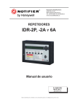
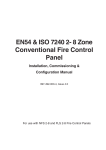
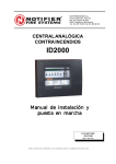
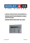
IDR
997-537-004-1, Issue 1 May 2006
-2A & -6A
repeaters user
manual
IDR-2A & -6A Repeaters User Manual
Quick Contents Reference by
Section
OPERATION - SEE SECTION 4
INTRODUCTION SEE SECTION 1
Contents
INSTALLATION SEE SECTION 2
COMMISSIONING SEE SECTION 3
ALSO:
SPECIFICATION - SEE APPENDIX 1
BATTERY CALCULATIONS - SEE APPENDIX 2
IDR-6A REPEATER LIMITATIONS - SEE APPENDIX 3
i
997-537-004-1, Issue 1
May 2006
IDR-2A & -6A Repeaters User Manual
Contents
1
Introduction
1
1.1
CE Marking
2
1.2
System Design and Planning
2
1.3
General
2
1.4
Related Documents
3
1.5
Warnings and Cautions
3
1.6
Tips
3
2
Installation Guide
Contents
2.1
Pre-Installation Check List
4
2.1.1 Some DO’s and DON’T’s
4
2.2
Transient Protection
5
2.3
Installation
6
2.3.1 Checking Your Repeater for Damage
6
2.3.2 What to do if Your Repeater is
Damaged or Suspect
7
2.4
Installation Options
8
2.5
Installing the Enclosure
9
2.5.1 Fixing Enclosure to Wall
9
2.5.2 Fitting the Label Inserts
10
2.6
Isolated RS232 Board (option)
11
2.7
Bezel Kit (option)
12
2.8
Installing the Wiring
13
2.8.1 External Wiring Connections
13
2.8.2 RS485 Serial Network - Address
Switches and Termination Resistors
14
2.8.3 ID2net Network via RS232 - Address
Switches
15
3
Commissioning
16
3.1
Preliminary Checks
16
3.2
Powering the Repeater
17
4
997-537-004-1, Issue 1
May 2006
4
Operation
18
4.1
Controls and Indicators
18
4.2
Menus - General Information
20
4.3
Menus: -2A (Except ID50)
21
4.3.1 Lamp Test
21
4.3.2 Power Diagnostics
21
ii
4.4
4.5
4.3.3 Pushbutton Test
22
4.3.4 Edit NORMAL Message
23
4.3.5 Restore NORMAL Message
23
4.3.6 Language
23
4.3.7 Cancel
24
Menus: -2A (ID50 Only)
24
4.4.1 LEDs/LCD/Buzzer Test
24
4.4.2 Pushbutton Test
25
4.4.3 Log
25
4.4.4 Edit NORMAL Message
25
4.4.5 Language
26
4.4.5 Cancel
26
Menus: -6A
27
4.5.1 Test
27
4.5.1.1 Lamp Test
27
4.5.1.2 Keypad Test
28
4.5.1.3 Cancel
28
4.5.2 Display Event Log
29
4.5.3 Configuration
29
4.5.3.1 Set Language
29
4.5.3.2 Set Function
30
4.5.3.3 Access Level for MUTE BUZZER
30
4.5.3.4 Silence/Resound Pushbutton Function 31
4.5.3.5 Event Options
31
4.5.3.6 Technical Alarm LED
31
Appendix 1 - Specification
A1 - 1
Appendix 2 - Battery Calculations
A2 - 1
Appendix 3 - IDR-6A Repeater Limitations A3 - 1
iii
997-537-004-1, Issue 1
May 2006
Contents
IDR-2A & -6A Repeaters User Manual
IDR-2A & -6A Repeaters User Manual
1
Introduction
This manual provides the user with all
necessary instructions for the installation,
commissioning and operation of an IDR
repeater.
ACCEPT
EVACUATE
SILENCE
SOUNDERS
RESOUND
SOUNDERS
There are two variants of the IDR repeater:
RESET
PRE-ALARM
FIRE
a. IDR-2A active repeater, with a 2 line x 40
character LCD.
TEST
FAULT
DELAY ACTIVE
DISABLEMENT
COMMUNICATIONS LOSS
SYSTEM FAULT
by Honeywell
POWER
b. IDR-6A active repeater, with a 6 line x 40
character LCD.
IDR-2A
MUTE
BUZZER
END DELAY/
EVACUATE
FIRE
SILENCE/
RESOUND
CHANGE
TABS
ZONES IN
ALARM
Procedures described in this manual include
appropriate warnings and cautions to guide the
user towards adopting safe and methodical
work practices during the installation,
commissioning and operational phases.
RESET
PRE-ALARM
TEST
FAULT
DELAY ACTIVE
DISABLEMENT
COMMUNICATIONS LOSS
SYSTEM FAULT
POWER
Introduction
MUTE
BUZZER
by Honeywell
IDR-6A
Important Note
This manual must be read, and its content
clearly understood, before proceeding with
any work relating to the IDR repeater.
Damage to the repeater and/or the fire
control panel(s) may result from NOT
following the recommended procedures
described in this manual.
If there are any areas of doubt, consult your
supplier before continuing with the system
installation or commissioning.
1
997-537-004-1, Issue 1
May 2006
IDR-2A & -6A Repeaters User Manual
1.1 CE Marking
The repeater is CE-Marked to show that it
conforms to the requirements of the following
European Community Directives:
Electromagnetic Compatibility Directive 89/
336/EEC (and the amending Directives
92/31/EEC and 93/68/EEC).
1.2 System Design and Planning
It is assumed that the system, of which the
IDR repeater is a part, has been designed by
a competent fire alarm system designer in
accordance with the requirements of EN54
Part 14 and any other local codes of practice
that are applicable.
1.3 General
Introduction
The IDR repeater has been designed to comply
with the requirements of EN54 Part 2,1997
when used as a secondary display.
The connection between repeaters and fire
control panels can be made either by an RS485
link or by an RS232 link (an optional Isolated
RS232 port can be fitted to allow connection
of Notifier-approved equipment).
Installation
The IDR repeaters are easy to install providing
the recommended procedures described in this
manual are followed. To avoid inadvertant
contamination of the PCB assemblies, the
manufacturer recommends that the enclosure
front door be covered during installation. An
optional Bezel kit containing a back box and bezel
is available for pre-installation, if required.
Cover the enclosure
front door during
installation, to protect
the LCD and the
printed circuit board
Commissioning
To commission the IDR repeaters follow the
recommended procedures described in this
manual.
Some fire control panels may require
configuration to associate the repeater with a
specific panel on the RS485 network; the
repeater then repeats that panel. Refer to the
documentation supplied with the fire control
panel for details of how to do this.
Operating
In addition to the repeat display of the fire
control panel, the IDR repeater includes some
repeater-unique menus to test the repeater
operation.
997-537-004-1, Issue 1
May 2006
2
IDR-2A & -6A Repeaters User Manual
1.4 Related Documents
This manual only describes the IDR repeater.
Refer to the documentation supplied with the
fire control panel for information about that
panel.
1.5 Warnings and Cautions
Where appropriate, this manual includes
advisory warnings and cautions to remind you
to consider safety at all times, especially when
following the procedures given herein. An
example is shown at left.
You MUST connect a
safety earth wire to the
IDR repeater, as described
opposite.
You are alerted to any areas where there may
be a risk of damage to static-sensitive devices
if the recommended procedures described in
this manual are not followed.
1.6 Tips
‘Handy tips’ are included, where appropriate,
to assist you in following quick and safe
procedures for system installation and
integration. Look for the ‘TIP!’ icon and
supporting text, typically illustrated at left.
For optimum performance
station address numbers
should be continuous.
3
997-537-004-1, Issue 1
May 2006
Introduction
An example of an anti-static caution is provided
to the left of this paragraph.
ATTENTION
Observe precautions for
handling Electrostatic
Sensitive Devices
IDR-2A & -6A Repeaters User Manual
2
Installation Guide
This Installation Guide provides simple
guidelines on how to install an IDR repeater
quickly and safely.
2.1 Pre-installation Check List
Before installing the IDR repeater you must
ensure that the following criteria have been
met. Failure to do this may not only result in
damage to the equipment, but may also cause
problems when commissioning the equipment
or may adversely affect its performance.
2.1.1 Some DO’s and DON’T’s
Installation Guide
Before selecting a location for the IDR
repeater, DO make sure that:
a. The operating ambient temperature is in the
recommended range:
+5°C to +35°C and
o
+35 C
5%
Min.
95%
Max.
b. The relative humidity is between:
o
+5 C
5% and 95%
c. The IDR repeater is wall mounted in a position
which allows clear visibility of displays and
easy access to operating controls. The height
above floor level should be chosen such that
the LCD is just above normal eye level
(approximately 1.5 metres).
1.5m
d. DO NOT locate the IDR repeater where it
is exposed to high levels of moisture.
997-537-004-1, Issue 1
May 2006
4
IDR-2A & -6A Repeaters User Manual
e. DO NOT locate the IDR repeater where
there are high levels of vibration or shock.
f. DO NOT site the IDR repeater where there
would be restricted access to the internal
equipment and cabling/wiring connections.
This equipment contains transient-protection
devices. Although no system is completely
immune from lightning transients and
interference, for these devices to function
correctly, and to reduce susceptibility, this
equipment must be earthed correctly.
As with all solid state devices, this system may
operate erratically or can be damaged if
subjected to lightning-induced transients.
The use of overhead or outside aerial wiring is
not recommended due to the increased
susceptibility to nearby lightning strikes.
5
997-537-004-1, Issue 1
May 2006
Installation Guide
2.2 Transient Protection
IDR-2A & -6A Repeaters User Manual
2.3 Installation
The IDR repeater is relatively simple to install
providing the recommended procedures
described in this Installation Guide are
followed.
Follow all installation instructions
described in this manual. These
instructions must be understood and the
manufacturer’s recommendations followed
to avoid damage to the IDR repeater, the
fire control panel and associated equipment.
To avoid damage to the IDR
repeater and to the fire
control panel, ensure that
you follow these
instructions
2.3.1 Checking Your Repeater for
Damage
Installation Guide
It is important to check all supplied
equipment for damage before proceeding
with the installation!
Before attempting to install your IDR repeater,
you should do the following:
1 After removing the IDR repeater from its
packaging, and before you proceed with
installing it in its chosen location, check for
any damage that may have been caused
while in transit.
Note: In the unlikely event that the IDR
repeater supplied has been damaged,
you MUST NOT install it but return it to
your supplier. The procedure for
returning faulty items is described in
Section 2.3.2, What to do if Your
Repeater is Damaged or Suspect.
2 If you are satisfied that the IDR repeater
has NOT been damaged you can now
commence the installation procedure. This
manual describes the recommended
installation methods of the IDR repeater.
Refer to the relevant sections that apply to
your configuration requirements.
To prevent unnecessary damage to the
electronic components, place a cover over the
front door while you fit the enclosure to the
wall. Refer to Section 2.5.1, Fixing Enclosure
to Wall for details.
997-537-004-1, Issue 1
May 2006
6
IDR-2A & -6A Repeaters User Manual
2.3.2 What to do if Your Repeater is
Damaged or Suspect
If you have problems regarding the quality of
any supplied order items including the IDR
repeater or this manual, or items are missing,
follow the procedure below:
1 DO NOT continue with the installation but
contact your supplier for advice on what to
do next.
2 To aid your supplier and the manufacturer,
you are requested to note all the details
relevant to your complaint, date of receipt,
packaging condition, etc. and forward this
to your supplier.
3 Where the product needs to be returned to
your supplier, you are requested to use the
original packaging wherever possible.
7
997-537-004-1, Issue 1
May 2006
Installation Guide
Similarly, if the product is found to be faulty
during installation contact your supplier
immediately.
IDR-2A & -6A Repeaters User Manual
2.4 Installation Options
Installation of the IDR repeater is described in
Section 2.5. The available options are
described as follows:
a. RS232 Board - Section 2.6. This allows
Notifier-approved equipment to be connected
to the IDR repeater.
b. Bezel Kit - Section 2.7. This allows the IDR
repeater to be flush-mounted.
Installation Guide
Wiring requirements are described in
Section 2.8.
b
a
997-537-004-1, Issue 1
May 2006
8
IDR-2A & -6A Repeaters User Manual
2.5 Installing the Enclosure
To ensure that the IDR repeater electronics
remain clean and undamaged, it is
recommended that the front door of the
enclosure be covered before the enclosure is
fixed to the wall. It is further recommended that
the cover remain in place while other trades
(e.g. plasterers or decorators) are working in
the vicinity, until the IDR repeater is ready for
commissioning.
DO NOT use the
enclosure as a guide
when drilling.
288.5
2.5.1 Fixing Enclosure to Wall
161.0
The drawing at left shows the IDR repeater
enclosure fixing dimensions in millimeters.
Fixing hole diameters are 5mm.
A
130.0
165.0
A
A
196.5
Note: The holes marked ‘A’ on the drawing are
provided for the bezel (Section 2.7).
Wall flatness
15.0
To prevent distortion, the IDR repeater
enclosure must be installed on a mounting
surface that is as flat as possible. If the wall is
not flat where the enclosure is to be fitted, use
appropriate packing pieces to level it up.
51.0
1
Procedure
On the suitable mounting surface:
2
1 Mark the position of the fixing holes.
2 Using an appropriate sized drilling bit, drill
and plug three holes in the mounting
surface.
3 Prepare apertures (20mm knockouts)
required for cable access.
3
4
4 Using three 5mm sized screws, fix the
enclosure to the mounting surface. Do not
use countersunk-headed screws.
COVER
9
997-537-004-1, Issue 1
May 2006
Installation Guide
A
IDR-2A & -6A Repeaters User Manual
2.5.2 Fitting the Label Inserts
With the IDR repeater door open and all power
disconnected, fit the label inserts as follows:
1 a. IDR-2A used with ID50 panel only. Fold
the IDR-2A pushbutton legends (345-429)
at the perforated line. Insert the legends
into the right-hand slot (see arrow ‘1’ on
drawing). The fold rests against the side of
the door. This insert has the legends MUTE
BUZZER through RESET inclusive. Ensure
correct orientation.
b. IDR-2A used with other panels. The
procedure is as given for 1a above, but use
legends with part number 345-420.
c. IDR-6A. The procedure is as given for
1a above, but use legends with part number
345-422.
Installation Guide
2 Fold the LH LEDS IDR legends (345-418)
insert FIRE through POWER at the
perforated line. Insert the legends into the
bottom right slot (arrow ‘2’ on drawing). The
fold rests on the bottom of the slot. Ensure
correct orientation.
3 Fold the RH LEDS IDR legends (345-419) insert
PRE-ALARM through COMMUNICATIONS
LOSS at the perforated line. Insert the
legends into the bottom left slot (arrow ‘3’
on drawing). The fold rests on the bottom
of the slot. Ensure correct orientation.
Note: The IDR repeater is supplied with
legends in a number of languages. Part
numbers given above are for English
language legends.
1
3
997-537-004-1, Issue 1
May 2006
10
2
IDR-2A & -6A Repeaters User Manual
2.6 Isolated RS232 Board (option)
This board is required only if Notifier-approved
equipment is to be connected to the IDR repeater.
ATTENTION
Observe precautions for
handling Electrostatic
Sensitive Devices
To fit the Isolated RS232 Board:
1 Use a hex key to open the IDR repeater
door (A).
1&2
A
C
2 Orientate the Isolated RS232 Board (B) as
shown and secure it to the IDR repeater
enclosure (C) using the four M3 X 8 SEM
screws (D) supplied with the Board.
Note: The Board is supplied with additional
fixings for other applications. These can
be discarded.
3 Connect the wiring (see drawing opposite).
B
Dx4
LOCATIONS
b. Use the supplied ribbon cable to
connect to the Termination Board.
3
TWO-PART
CONNECTOR FOR
EQUIPMENT
To remove the Isolated RS232 Board, reverse
the procedure for fitting it.
CONNECTION
TO TERMINATION
BOARD
11
997-537-004-1, Issue 1
May 2006
Installation Guide
a. Use screened multi-core cable to
connect the equipment.
IDR-2A & -6A Repeaters User Manual
2.7 Bezel Kit (option)
1&4
A
The bezel is supplied with a dedicated back
box which has fixing holes, three on the rear
wall and two on each side wall. This procedure
describes fixing using the rear wall fixing holes,
although the procedure can be applied to the
side fixing holes. To install the kit:
1 At the repeater installation location, make a
recess (A) in the vertical surface large enough
for the back box (B) to be fully inserted easily
and without unnecessary force. The size of
the recess must also allow for space required
for cable entry into the back box. With the
bezel (C) still attached to the back box, offer
the assembly to the recess to check for
correct depth and clearance. Repeat this
process until the correct depth and
clearances have been achieved.
2 Support the bezel/back box assembly in the
desired position in the recess and mark the
three screw fixing positions (X) as shown
at left. Remove the assembly from the
recess. Using an appropriate sized drilling
bit, drill and plug three holes to take up to
No. 8 (4mm) wood screws. Alternatively,
use the side fixing holes (Y).
3 Prepare all required knockouts, and fit cable
glands as required (see Section 2.8.1).
CAUTION: To avoid distortion of the back
box when preparing knockouts, place the
appropriate back box face on a supporting
surface (e.g. work bench).
4 Orientate the bezel/back box assembly correctly,
offer it to the recess, then feed the cables through
the glands and take up any excess slack. Secure
the assembly in position using appropriate-sized
screws (D) - do not use countersunk-headed
screws. To avoid distorting the bezel and/or back
box (making it difficult to fit the IDR repeater),
do not over-tighten these screws.
5 After the bezel/back box assembly (E) has been
successfully installed, prepare the IDR repeater
(F) for fitting by preparing knockouts, as required,
for bringing in all cables for termination. Insert
one of the supplied cable grommets (G) into
the upper knockout on the rear wall of the IDR
repeater. Orientate the IDR repeater correctly,
hold the door open and offer the IDR repeater
to the installed bezel/back box assembly. Feed
all cables through the prepared knockouts and
fully insert the IDR repeater into the bezel/back
box aperture. Use the four M4 SEM screws (H)
supplied in the kit to secure the IDR repeater
to the assembly using the four holes (Z).
6 Connect the free end of the earth lead (I)
to the earth connector (J) provided on the
inside of the IDR repeater enclosure (top
left corner). Use a suitable-sized, crossheaded screwdriver to tighten at earth point
to ensure a good earth connection is made.
B C
1
1
1
2
254
88
58
132
Rear View
X
Y
22
X
X
130
22
22
175
92
Installation Guide
D (x3)
Y
Side
View
All dimensions in millimetres
2&3
!
5&6
I
‘A’
E
Z
Z
Z
J
6
F
Z
G
6
A
H (x4)
997-537-004-1, Issue 1
May 2006
12
IDR-2A & -6A Repeaters User Manual
2.8 Installing the Wiring
2.8.1 External Wiring Connections
SEE
DETAIL ‘A’
The following external wiring must be
terminated at the Termination Board:
a. 28V IN (18-32V dc) and 0V supply, from
previous repeater, or from panel, or from
external source.
RIBBON
TO/FROM
CONTROL
PCB
0V IN
28V IN
0V OUT
28V OUT
Note: If dc power is derived from the fire
control panel, do not exceed the available
current (refer to panel specification).
b. 28V OUT (18-32V dc) and 0V to next repeater.
0V
c. Power Fail (PF) input. Connect to the power
supply unit’s power fail output or, if there is
no such output, link the PF terminal to the
0V terminal immediately above it.
DETAIL ‘A’
TERMINATION
PCB 124-318
Note: If the PF signal goes high or becomes
disconnected, the LCD backlight
extinguishes 10 seconds after the
failure. It illuminates again if any
pushbutton is operated, then extinguishes
again after 10 seconds.
Termination
Legend
RIBBON
TO OPTIONAL
RS232 PCB
d. RS485 serial data link (A and B) from the
previous station in the network (where
‘station’ is a fire control panel, repeater or
mimic display).
Only connect power
cables when the
system power is OFF.
e. RS485 serial data link (A and B) to the next
station in the network.
Note: Further information about the RS485
serial data link is given in Section 2.8.2.
Only terminate the IDR
repeater power cables at
the fire control panel after
ALL pre-commissioning
checks have been done.
The following external wiring must be
terminated at the enclosure:
a. Safety earth wire. Connect this to the
safety earth point, which is clearly
marked on the inside top left of the
enclosure rear wall - see ‘Detail A’.
You MUST connect a
safety earth wire to the
IDR repeater, as described
opposite.
Notifier-approved equipment (Network
Gateway Unit) may be connected at the
optional RS232 board as described in
Section 2.8.3.
All external wiring must be screened and
terminated, using any suitable plastic glands,
to meet local wiring codes. Terminate screens
at the repeater earth point (see detail ‘A’). To
satisfy EMC requirements, route the wiring
along the edges of the enclosure as shown
opposite. Use cable ties to secure the wiring
at the tie down slots provided.
13
997-537-004-1, Issue 1
May 2006
Installation Guide
POWER
FAIL
RS485
A IN
RS485
B IN
RS485
A OUT
RS485
B OUT
IDR-2A & -6A Repeaters User Manual
2.8.2 RS485 Serial Network - Address
Switches and Termination
Resistors
The RS485 network is connected to the
Termination Board as shown in Section 2.8.1.
The following must be set during configuration:
Each station address
MUST be unique. No
two stations may have
the same address.
a. The IDR repeater address; this is set in the
range 1 to 31 in binary by using the first 5
switches (A) on the Control Board (address
0 - all switches set to 0 - sets the repeater
for ‘listen only’ and must only be used during
commissioning). The decode is given
below. Switch 6 must be set to 0 (it is set to
1 in applications which use addresses
above 31).
For optimum performance
station address numbers
should be continuous.
Note: If the IDR repeater is used with an ID50
fire control panel, the address must be
set in the range 1 to 16.
Installation Guide
b. Switch 7 must be set according to the type
of connection used by the repeater, in this
case 0 for RS485 (does not have to be the
same as in (c) below).
c. Set switch 8 according to the type of
network used by the fire panel; set to 0 if
an RS485 network (i.e. Master/Slave) is
used, or to 1 if an ID2net network is used.
d. If the IDR repeater is at either end of the
RS485 network, TERM ON jumpers JP2/
4/6 (B) on the Control Board must be fitted
to put the line termination resistors in circuit.
If the IDR repeater is not at either end of
the network, these jumpers must not be
fitted (the link supplied on the Control Board
should be placed across TERM OFF
jumpers JP1/3/5).
Address
1
2
3
4
5
6
7
8
9
10
11
12
13
14
15
16
17
18
19
20
21
22
23
24
25
26
27
28
29
30
31
1
1
0
1
0
1
0
1
0
1
0
1
0
1
0
1
0
1
0
1
0
1
0
1
0
1
0
1
0
1
0
1
Switch
2
0
1
1
0
0
1
1
0
0
1
1
0
0
1
1
0
0
1
1
0
0
1
1
0
0
1
1
0
0
1
1
The IDR repeater must be associated with the
fire control panel it is to repeat; refer to the fire
control panel documentation for the procedure.
settings (1=on)
3
4
5
6
0
0
0
0
0
0
0
0
0
0
0
0
1
0
0
0
1
0
0
0
1
0
0
0
1
0
0
0
0
1
0
0
0
1
0
0
0
1
0
0
0
1
0
0
1
1
0
0
1
1
0
0
1
1
0
0
1
1
0
0
0
0
1
0
0
0
1
0
0
0
1
0
0
0
1
0
1
0
1
0
1
0
1
0
1
0
1
0
1
0
1
0
0
1
1
0
0
1
1
0
0
1
1
0
0
1
1
0
1
1
1
0
1
1
1
0
1
1
1
0
1
1
1
0
997-537-004-1, Issue 1
May 2006
14
IDR-2A & -6A Repeaters User Manual
2.8.3 ID2net Network via RS232 Address Switches
The ID2net is connected by one of two methods
as shown in the diagrams below. Connections
to the Isolated RS232 Board are shown in
Section 2.6. DC power connections are shown
in Section 2.8.1. The following must be set
during configuration:
Address
1
2
3
4
5
6
7
8
9
10
11
12
13
14
15
16
17
18
19
20
21
22
23
24
25
26
27
28
29
30
31
32
33
34
35
36
37
38
39
40
41
42
43
44
45
46
47
48
49
50
51
52
53
54
55
56
57
58
59
60
61
62
63
1
1
0
1
0
1
0
1
0
1
0
1
0
1
0
1
0
1
0
1
0
1
0
1
0
1
0
1
0
1
0
1
0
1
0
1
0
1
0
1
0
1
0
1
0
1
0
1
0
1
0
1
0
1
0
1
0
1
0
1
0
1
0
1
Switch
2
0
1
1
0
0
1
1
0
0
1
1
0
0
1
1
0
0
1
1
0
0
1
1
0
0
1
1
0
0
1
1
0
0
1
1
0
0
1
1
0
0
1
1
0
0
1
1
0
0
1
1
0
0
1
1
0
0
1
1
0
0
1
1
b. Switch 7 must be set according to the type
of connection used by the repeater, in this
case 1 for ID2net via an RS232 link.
settings (1=on)
3
4
5
6
0
0
0
0
0
0
0
0
0
0
0
0
1
0
0
0
1
0
0
0
1
0
0
0
1
0
0
0
0
1
0
0
0
1
0
0
0
1
0
0
0
1
0
0
1
1
0
0
1
1
0
0
1
1
0
0
1
1
0
0
0
0
1
0
0
0
1
0
0
0
1
0
0
0
1
0
1
0
1
0
1
0
1
0
1
0
1
0
1
0
1
0
0
1
1
0
0
1
1
0
0
1
1
0
0
1
1
0
1
1
1
0
1
1
1
0
1
1
1
0
1
1
1
0
0
0
0
1
0
0
0
1
0
0
0
1
0
0
0
1
1
0
0
1
1
0
0
1
1
0
0
1
1
0
0
1
0
1
0
1
0
1
0
1
0
1
0
1
0
1
0
1
1
1
0
1
1
1
0
1
1
1
0
1
1
1
0
1
0
0
1
1
0
0
1
1
0
0
1
1
0
0
1
1
1
0
1
1
1
0
1
1
1
0
1
1
1
0
1
1
0
1
1
1
0
1
1
1
0
1
1
1
0
1
1
1
1
1
1
1
1
1
1
1
1
1
1
1
1
1
1
1
c. Set switch 8 according to the type of
network used by the fire panel, in this case
1 for an ID2net network.
15
997-537-004-1, Issue 1
May 2006
Installation Guide
a. The IDR repeater address; this is set in the
range 1 to 63 in binary by using the first 6
switches (A) on the Control Board. The
decode is given below. Addresses above
63 can only be set by using the Off-line
Configuration Tool (in this case the address
switches must all be set to 0). Address 0 is
not valid for ID2net.
IDR-2A & -6A Repeaters User Manual
3
Commissioning
This section gives the procedure for
commissioning the IDR repeater.
Only terminate the IDR
repeater power cables at
the fire control panel
after ALL preliminary
checks have been done.
Commissioning consists of:
a. Preliminary checks.
b. Power-up checks.
ATTENTION
Observe precautions for
handling Electrostatic
Sensitive Devices
3.1 Preliminary Checks
Carry out the following preliminary checks for
EVERY IDR repeater being commissioned,
prior to powering-up the system:
Commissioning
1 Check that all cables brought into the IDR
repeater have been terminated correctly.
The connection of external wiring is
described in Section 2.8.1. All power and
signal cabling and wiring must conform to
the appropriate local regulation.
2 Check that the address has been set
correctly as described in Section 2.8.2
(RS485 network) or Section 2.8.3 (ID2net
network).
997-537-004-1, Issue 1
May 2006
16
IDR-2A & -6A Repeaters User Manual
3.2 Powering the Repeater
The IDR repeater obtains 18-32V and 0V dc
supplies either from the fire control panel
auxiliary outputs or, depending upon the IDR
repeater’s location, from a local independent
power supply. Connections are made as
described in Section 2.8.1.
It is important to follow the procedure
below when powering-up/down the IDR
repeaters for maintenance and system
upgrades, NOT just when commissioning
the IDR repeater.
To power-up the IDR repeater:
2 Check that the LCD shows the System
Status Normal display (on IDR-6A repeater
a list of available languages is displayed
first; use the repeater’s pushbuttons to
select [see Section 4.5.3.1]). You may need
to adjust the contrast (see Section 4).
To power-down the IDR repeater, power down
the fire control panel (including battery
disconnection), then power down any IDR
repeaters that use local independent supplies.
The repeater CAN be powered down first, but
the panel will then report a fault.
17
997-537-004-1, Issue 1
May 2006
Commissioning
1 Power-up the fire control panel and powerup any IDR repeaters that use a local
independent supply.
IDR-2A & -6A Repeaters User Manual
4
Operation
4.1 Controls and Indicators
MUTE
BUZZER
FIRE
END DELAY/
EVACUATE
SILENCE/
RESOUND
RESET
MUTE
BUZZER
PRE-ALARM
FIRE
TEST
FAULT
DELAY ACTIVE
DISABLEMENT
COMMUNICATIONS LOSS
SYSTEM FAULT
POWER
by Honeywell
EVACUATE
SILENCE
SOUNDERS
RESOUND
SOUNDERS
RESET
PRE-ALARM
TEST
FAULT
DELAY ACTIVE
DISABLEMENT
COMMUNICATIONS LOSS
SYSTEM FAULT
POWER
IDR-2A repeater (2 x 40 display)
installed for use with ID50 fire control panel
Operation
ACCEPT
by Honeywell
IDR-2A repeater installed for other applications
PUSHBUTTONS (IDR-2A - ID50
APPLICATION)
PUSHBUTTONS (IDR-2A - OTHER
APPLICATIONS)
Silences repeater and panel buzzers
(locally and across the network).
Silences repeater and panel buzzers
(locally and across the network).
Sounds all sounders configured for
Evacuate. Any active delays are
cancelled.
Accepts an alarm and silences the IDR
repeater’s internal buzzer.
Sounds all sounders configured for
Evacuate.
Stops and restarts the sounders.
Stops the sounders.
Restores normal operating status when
all alarm conditions have been removed.
Restarts the sounders.
Restores normal operating status when
all alarm conditions have been removed.
997-537-004-1, Issue 1
May 2006
18
IDR-2A & -6A Repeaters User Manual
PUSHBUTTONS (IDR-6A)
Silences repeater and panel buzzers
(locally and across the network), and
accepts an alarm.
MUTE
BUZZER
END DELAY/
EVACUATE
SILENCE/
RESOUND
CHANGE
TABS
ZONES IN
ALARM
RESET
If any delays are active, first operation
ends the delays, second operation
sounds all sounders configured for
Evacuate. If no delays are active, first
operation performs Evacuate.
PRE-ALARM
FIRE
TEST
FAULT
DELAY ACTIVE
DISABLEMENT
COMMUNICATIONS LOSS
SYSTEM FAULT
POWER
by Honeywell
Stops and restarts the sounders.
IDR-6A repeater (graphics display)
Steps through the tabbed displays.
LCD CONTRAST ADJUSTMENT
Restores normal operating status when
all alarm conditions have been removed.
Contrast can also be adjusted during Lamp Test
(see Section 4.5.1).
KEYSWITCH (IDR-2A, -6A)
2A
Setting the keyswitch to the right selects
access level 2. Setting it to the centre
de-selects access level 2. The procedures
given in Sections 4.3 onwards require access
level 2, unless stated otherwise.
OR (ID50 REPEATER ONLY)
6A
TURN KEYSWITCH WHEN THE
DISPLAY IS AS SHOWN ABOVE
19
997-537-004-1, Issue 1
May 2006
Operation
Displays fire alarm information. If there
are fire alarms in more than one zone,
steps through these zones.
Set keyswitch to right, press and hold
then press
RESET momentarily. The LCD contrast cycles.
when the contrast is satisfactory, then
Press
use
and
to fine-tune. Press
when finished.
IDR-2A & -6A Repeaters User Manual
KEYPAD PUSHBUTTONS (IDR-2A, -6A)
Used to move around the LCD menus. On
is the Cancel
ID50 repeaters only,
pushbutton.
Used to select repeater-specific menus (-2A)
and to select various menu options, as defined
on the menus (-2A, -6A).
LEDs (IDR-2A, -6A)
A fire condition exists.
A fault condition exists.
There is a disablement on the system (for
ID2000 panels, on the associated panel).
Operation
The dc power supply to the IDR repeater is
present and the IDR processor is operating.
A pre-alarm condition exists.
There is a test occurring on the system.
There is an active delay on the system.
The fire control panel has a system fault.
A network communications problem has
occurred and the IDR repeater information is
not reliable.
Spare.
4.2 Menus - General Information
Press
(-2A) or operate the keyswitch (-6A)
to enter the IDR repeater-unique menus
system as access level 2 is required. Use the
and
pushbuttons to select the desired
menu. All these menus incorporate a time-out;
if no pushbuttons are operated within the timeout period the IDR repeater reverts to the
display prior to the menu being accessed.
997-537-004-1, Issue 1
May 2006
20
IDR-2A & -6A Repeaters User Manual
4.3 Menus: -2A (Except ID50)
4.3.1 Lamp Test
All pixels on the LCD are switched on and then
off, the buzzer sounds intermittently, and the
LEDs light sequentially in a continuous pattern
from bottom right to top left.
If no change is made to the contrast, the test
stops automatically and the LCD returns to the
display prior to test.
4.3.2 Power Diagnostics
The LCD returns to the repeat display
automatically.
The nominal power supplies should be within
the following voltage ranges:
21
Supply
Range
28V
+18V to +32V
-15V
-12V to -17V
+10V
+7V to +12V
-10V
-7V to -12V
Buzzer
+18V to +32V (buzzer off)
997-537-004-1, Issue 1
May 2006
Operation
To change the contrast of the LCD, press the
or
pushbuttons repeatedly to give the
best display, then press
to return to the
display prior to test.
IDR-2A & -6A Repeaters User Manual
4.3.3 Pushbutton Test
Press each pushbutton in turn. Verify that:
a. The buzzer beeps.
b. The LCD displays the name of the
pushbutton.
c. The corresponding LED as shown at the
left illuminates.
Turn the keyswitch to access level 1 to exit
the test.
AND AS FOLLOWS:
Operation
PUSHBUTTON
ILLUMINATES LED
TEST
DELAY ACTIVE
SYSTEM FAULT
MUTE BUZZER
ACCEPT
EVACUATE
SILENCE SOUNDERS
RESOUND SOUNDERS
RESET
COMMUNICATIONS LOSS
Upper General FIRE
Lower General FIRE
Upper General FAULT
Lower General FAULT
DISABLEMENT
POWER
997-537-004-1, Issue 1
May 2006
22
IDR-2A & -6A Repeaters User Manual
4.3.4 Edit NORMAL Message
This option lets you change the message that
is displayed on the lower line of the LCD when
the system status is normal.
1 Use the
and
pushbuttons to select
the character to be edited - it blinks. Use
the
and
pushbuttons to scroll through
the available character set until the required
replacement character is displayed. Select
the next character to be edited, and so on.
2 When all edits are complete, press
exit from the message editor.
to
4.3.5 Restore NORMAL Message
To use the repeater’s default message instead
of the message edited at the repeater, select
this menu option and press
.
DEFAULT NORMAL MESSAGE IS USED
4.3.6 Language
Use the
and
pushbuttons to scroll
through the available languages. Press
to
select the language currently-displayed.
REPEATER DISPLAYS ARE IN SELECTED
LANGUAGE
23
997-537-004-1, Issue 1
May 2006
Operation
Note: To exit from the message editor without
saving changes, do not press
.
Instead, turn the keyswitch to return to
access level 1.
IDR-2A & -6A Repeaters User Manual
4.3.7 Cancel
This option exits from the repeater-specific
menus.
RETURN TO REPEAT DISPLAY
4.4 Menus: -2A (ID50 Only)
4.4.1 LEDs/LCD/Buzzer Test
Operation
All pixels on the LCD are switched on and then
off, the buzzer sounds intermittently, and the
LEDs light sequentially in a continuous pattern
from bottom right to top left.
To change the contrast of the LCD, press the
or
pushbuttons repeatedly to give the
best display, then press
to return to the
display prior to test.
If no change is made to the contrast, the test
stops automatically and the LCD returns to the
display prior to test.
997-537-004-1, Issue 1
May 2006
24
IDR-2A & -6A Repeaters User Manual
4.4.2 Pushbutton Test
Press each pushbutton in turn. Verify that:
a. The buzzer beeps.
b. The LCD displays the name of the
pushbutton (does not for pushbuttons that
are not used).
Turn the keyswitch to access level 1 to exit
the test.
4.4.3 Log
Operation
Use the
and
arrows to scroll through
the log messages. Press
to return to the
System Normal display.
4.4.4 Edit NORMAL Message
This option lets you change the message that
is displayed on the top line of the LCD when
all systems are normal.
1 Use the
and
pushbuttons to select
the character to be edited - it blinks. Use
the
and
pushbuttons to scroll through
the available character set until the required
replacement character is displayed. Select
the next character to be edited, and so on.
2 When all edits are complete, press
exit from the message editor.
to
Note: To exit from the message editor without
saving changes, do not press
.
Instead, turn the keyswitch to return to
access level 1.
25
997-537-004-1, Issue 1
May 2006
IDR-2A & -6A Repeaters User Manual
4.4.5 Language
Use the
and
pushbuttons to scroll
through the available languages. Press
to
select the language currently-displayed.
REPEATER DISPLAYS ARE IN SELECTED
LANGUAGE
Operation
4.4.6 Cancel
This option exits from the repeater-specific
menus.
RETURN TO REPEAT DISPLAY
997-537-004-1, Issue 1
May 2006
26
IDR-2A & -6A Repeaters User Manual
4.5 Menus: -6A
Use the
pushbutton to select the required
menu option.
4.5.1 Test
All pixels on the LCD are switched on and then
off, the buzzer sounds intermittently, and the
LEDs light sequentially in a continuous pattern
from bottom right to top left.
To change the contrast of the LCD, press the
or
pushbuttons repeatedly to give the
best display, then press
to return to the User
Menu.
If no change is made to the contrast, the test
stops automatically and the LCD returns to the
User Menu.
27
997-537-004-1, Issue 1
May 2006
Operation
4.5.1.1 Lamp Test
IDR-2A & -6A Repeaters User Manual
4.5.1.2 Keypad Test
Operation
Press each repeater pushbutton in turn and
verify that the corresponding square on the
LCD becomes momentarily solid black. The
example shows the test display when
CHANGE TABS is operated.
Turn the keyswitch counter-clockwise to exit
the test and return to the display prior to test.
4.5.1.3 Cancel
This menu option exits from the Test Menu and
re-displays the User Menu.
997-537-004-1, Issue 1
May 2006
28
IDR-2A & -6A Repeaters User Manual
4.5.2 Display Event Log
Use the
and
pushbuttons to scroll
through the logged events by event number.
Press the
pushbutton to exit the log. The
repeater returns to the display shown prior to
entering the log.
Operation
4.5.3 Configuration
4.5.3.1 Set Language
Configuration Menu:
1:Set Language
2:Set Function
3:Access Level for MUTE BUZZER
4:Silence/Resound pushbutton function
User
Tue 05-Nov-2001 11:20:07
Use the
and
pushbuttons to select the
required language from those available, then
press the
pushbutton to return to the User
menu.
29
997-537-004-1, Issue 1
May 2006
IDR-2A & -6A Repeaters User Manual
4.5.3.2 Set Function
This option ensures that the IDR-6A repeats
the panel display in the correct manner.
Configuration Menu:
1:Set Language
2:Set Function
3:Access Level for MUTE BUZZER
4:Silence/Resound pushbutton function
User
Tue 05-Nov-2001 11:20:07
Use the
and
pushbuttons to select the
required function (or cancel):
a. Standard. Select this if the Panel Settings
of the panel being repeated are set to
Standard using local zones.
b. VdS. Select this if the Panel Settings of the
panel being repeated are set to VdS using
local zones.
c. Standard, ‘Zone/Ref.’ nomenclature. Select
this if the Panel Settings of the panel being
repeated are set to Standard using network
zones.
Operation
d. VdS, ‘Zone/Ref.’ nomenclature. Select this
if the Panel Settings of the panel being
repeated are set to VdS using network
zones.
If the function has been changed, press the
pushbutton to confirm and return to the
User Menu.
4.5.3.3 Access Level for MUTE BUZZER
This option selects the access level at which
the MUTE BUZZER pushbutton can be
operated (level 2 = keyswitch operation).
Configuration Menu:
1:Set Language
2:Set Function
3:Access Level for MUTE BUZZER
4:Silence/Resound pushbutton function
User
Tue 05-Nov-2001 11:20:07
997-537-004-1, Issue 1
May 2006
and
pushbuttons to select the
Use the
required level, then press the
pushbutton
to return to the User menu.
30
IDR-2A & -6A Repeaters User Manual
4.5.3.4 Silence/Resound Pushbutton
Function
By default, option 1 is selected. Option 2 is
only available if VdS (local or network zones)
is selected at the ‘Set Function’ menu.
Configuration Menu:
1:Set Language
2:Set Function
3:Access Level for MUTE BUZZER
4:Silence/Resound pushbutton function
User
Tue 05-Nov-2001 11:20:07
Option 2 is only provided for compatability with
older German systems for which the panel
(and repeaters) have this pushbutton labelled
‘Akustik AB/AN’. If the pushbutton is labelled
‘Akustik AN-/Anstellen’ then option 1 must be
selected.
and
pushbuttons to select the
Use the
required level, then press the
pushbutton
to return to the User menu.
Configuration Menu:
2:Set Function
3:Access Level for MUTE BUZZER
4:Silence/Resound pushbutton function
5:Event Options
User
Tue 27-Jul-2004 11:20:07
By default, option 1 is selected and all events
are repeated. If option 2 is selected, only Fire
Alarm events are repeated.
Event Options:
1:Display all events
2:Display ALARMS ONLY
User
Use the
and
pushbuttons to select the
required option, then press the
pushbutton
to return to the User menu.
Tue 27-Jul-2004 11:20:07
4.5.3.6 Technical Alarm LED
Configuration Menu:
3:Access Level for MUTE BUZZER
4:Silence/Resound pushbutton function
5:Event Options
6:Technical Alarm LED
User
Tue 27-Jul-2004 11:20:07
By default, option 1 is selected. If option 2 is
chosen, the PRE-ALARM LED is used to
indicate TECHNICAL ALARM instead.
Technical Alarm LED:
1:NO
2:YES
User
Use the
and
pushbuttons to select the
required option, then press the
pushbutton
to return to the User menu.
Tue 27-Jul-2004 11:20:07
31
997-537-004-1, Issue 1
May 2006
Operation
4.5.3.5 Event Options
IDR-2A & -6A Repeaters User Manual
Appendix 1 - Specification
Construction:
Dimensions (mm):
Weight:
Fixing:
Cable Entry:
Terminals:
Mild steel sheet enclosure. All displays
and controls are carried on the
enclosure door.
165.0(h) x 288.5(w) x 50.0(d)
1.8kg approx.
Three mounting holes in enclosure
5 x 20mm knockouts in top of enclosure
3 x 20mm knockouts in back of enclosure
External connections made using
screw terminals capable of accepting
cable sizes between 0.5mm 2 and
2.5mm2
Environmental:
Climatic classification: 3K5, (IEC 721-2-3)
Operating temperature: -5°C to +45°C, (recommended +5°C
to 35°C)
Humidity:
5% to 95% R.H.
Height above sea level: Maximum, 2000m
Panel sealing:
IP 30, (EN 60529)
Vibration:
EN 60068-2-6, 10-150Hz at 0.981ms-2
(Meets the requirements of EN 54-2/4)
EMC:
Emissions:
EN 61000-6-3
Immunity:
EN 50130-4
Safety:
EN 60950
Electrical
Operating Voltage:
Quiescent Current:
Alarm Current:
Maximum Fault Current:
Comms. Medium:
Address Range:
18-32V
90mA
120mA (-2A), 155mA (-6A)
Resettable thermal fuse. Nominal 250mA; absolute max. 600mA
RS485 2-wire serial link or RS232 link
Switch-selectable in range 0-63
(maximum address depends upon the
type of fire panel, and the type of
network used. Master/Slave: address
0 is unmonitored and must not be used
except during power-up commissioning
check. ID2net: address 0 cannot be
used)
RS485 Isolated Serial Port
Isolation:
Functional at 42V
Baud rate:
1200 Baud
Connector:
Screw terminals on Termination Board
Maximum cable length: 3000m (minimum of 1mm2 screened
cable recommended)
A1 - 1
997-537-004-1, Issue 1
May 2006
Appendix 1 - Specification
Mechanical
IDR-2A & -6A Repeaters User Manual
RS232 Serial Port - Temporary PC connection
Baud rate:
Connector:
Max cable length:
9600 Baud
D-type on Control Board
5m
RS232 Isolated Serial Port (Optional) - Notifier-approved Equipment
Isolation:
Baud rate:
Connector:
Max cable length:
Functional at 42V
9600 Baud
Terminal block on RS232 Board
15m
Display and Indications:
Appendix 1 - Specification
Alphanumeric Display:
LED Indicators:
IDR-2A uses 2 x 40 character LCD
IDR-6A uses 64x240 pixel LCD
(arranged to give 6 lines of characters)
General
FIRE
and
FAULT,
DISABLEMENT, POWER, PREALARM, TEST, DELAYACTIVE, SYSTEM
FAULT, and COMMUNICATIONS LOSS
Controls
Pushbuttons - 2A (ID50): MUTE BUZZER, END DELAY/
EVACUATE, SILENCE/RESOUND,
RESET
Pushbuttons - 2A (other): MUTE BUZZER, ACCEPT, EVACUATE,
SILENCE SOUNDERS, RESOUND
SOUNDERS, RESET
Pushbuttons - 6A:
MUTE BUZZER, END DELAY/
EVACUATE, SILENCE/RESOUND,
CHANGE TABS, ZONES IN ALARM,
RESET
Keypad - 2A/6A
,
,
,
and
Buzzer
In order of decreasing priority:
Fire:
Continuous pulses
Pre-alarm:
3 pulses every 12 seconds
Fault:
Continuous tone
Fire (accepted):
3 pulses every 12 seconds
Pre-alarm (accepted):
3 pulses every 12 seconds
Fault (accepted)
1 pulse every 2 minutes
Disablement
1 pulse every 2 minutes
997-537-004-1, Issue 1
May 2006
A1 - 2
IDR-2A & -6A Repeaters User Manual
Appendix 2 - Battery Calculations
During the quiescent period it is reasonable to assume that
the minimum voltage from the battery will be 24V for the vast
majority of the time. On this premise the 24V supply figure
can be used for all systems during this period.
In alarm the final battery voltage may fall to 19V. Allowing up
to 1V for cable and other losses, the worst-case supply voltage
for non-boosted systems may be as low as 18V. This results
in higher currents in alarm for these systems.
Boosted: ID2000, ID2008, ID/NF3000, NF300
Non-Boosted: ID50, ID1000, PS2, PS2/CMX, PS2/701
A non-boosted panel/PSU will require the following battery
capacity to support the IDR Repeater:
C = (T x Iq + Ia) x 1.25
where:
C is the calculated battery capacity in Ampere-Hours
T is the required battery backup time in Hours
lq is the IDR repeater quiescent current in Amperes
la is the IDR repeater alarm current in Amperes
1.25 is a multiplying constant to comply with LPS1014
If connected to the auxiliary output of a boosted panel the
efficiency of the panel’s booster must be allowed for. Notifier
recommend using the Loop and Battery Calculator Tool to
calculate the total battery capacity required. An approximation
can be obtained by multiplying the currents given below by 1.7.
The currents (excluding Isolated RS232 Board) at the above
voltages are:
IDR-2A
Quiescent
Alarm
@18V
90mA
120mA
@24V
80mA
100mA
@18V
90mA
155mA
@24V
80mA
125mA
IDR-6A
Quiescent
Alarm
If an Isolated RS232 Board is fitted, add 5mA to these values.
When calculating the battery requirements it is recommended
that the 18V alarm current and the 24V quiescent current be
used.
A2 - 1
997-537-004-1, Issue 1
May 2006
Appendix 2 - Battery Calculations
At present, Notifier Panels/PSUs fall into the following groups:
IDR-2A & -6A Repeaters User Manual
Appendix 3 - IDR-6A Repeater Limitations
Limitation
Applicability of the limitation
Repeater is on
RS232, panels
are on ID2net
Repeater is on
RS485 to local
panel, panels
are on ID2net
Repeater and
panels are on
Master/Slave
APPLIES
APPLIES
APPLIES
DOES NOT
APPLY
APPLIES
APPLIES
DOES NOT
APPLY
APPLIES
DOES NOT
APPLY, BUT
THERE MAY
STILL BE
ERRORS IN
THE
DISPLAY
APPLIES
APPLIES
APPLIES
DOES NOT
APPLY
APPLIES
APPLIES
If ‘Alarm Outputs by Zone’ for ‘All Zones’ is selected at the
panel, the sounder circuits are included in the disablement.
Because the repeater does not receive information about
the sounder circuits, it displays a general message
‘SOUNDER CIRCUIT (all) Panel n’, in addition to the zone
message.
Disablements - detailed display
When a zone is disabled, the repeater is unable to display
details of the devices disabled within the zone, nor the
zone name. The device total will not be correct. This applies
both to the local panel and to remote panels.
Enablements by device
If a disabled zone on the panel to which the repeater is
connected is re-enabled by enabling every device
individually, the zone is then no longer displayed as
disabled. However, if the zone is on a remote panel it
continues to be displayed as disabled, because the
repeater does not receive information about devices on
these panels.
Delay Active
The repeater has a DELAY ACTIVE LED which illuminates
steady when the panel’s DELAYS ACTIVE LED is lit. If a
delay is in progress, the panel’s LED flashes and its LCD
shows a timer bar. The repeater does not receive this
progress information and its LED remains steady.
Walk Test
During a walk test, the repeater does not display untested
devices, nor the ‘Not Tested’ total. This applies both to the
local panel and to remote panels.
A3 - 1
997-537-004-1, Issue 1
May 2006
Appendix 3 - IDR-6ARepeater Limitations
Alarm Outputs Disablements
PREVENT
SS
N
TIO BOA
CA
local distributor
R
N CE TIFI
IO
LO
T: +44 (0) 1444 230 300
F: +44 (0) 1444 230 888
E:
[email protected]
www.notifierfiresystems.co.uk
RD
Charles Avenue
Burgess Hill
W. Sussex
RH15 9UF
007
Quality Systems Certificate No. 154
Assessed to ISO9001
Every care has been taken in the preparation of this document but no liability can be accepted for the use of the information therein. Design features may be changed or amended without prior notice.