1
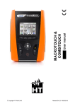
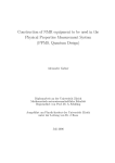
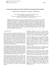
Agilent Technologies 5186-5190 Algorithm User Manual Agilent Technologies, Silverstone House, Ballymoss Road, Sandyford Industrial Estate, Dublin 18, Ireland Phone 353-1-6058320 • Fax 353-1-6058321 All rights reserved. No part of this document may be stored in a retrieval system, transmitted, or used in any form or by any means, electronic, mechanical, photocopying, recording or otherwise without the prior permission of the copyright holder. Agilent Technologies retains the right to modify this document without notice. 5186-5190-A 1 Agilent Technologies 5186-5190 Revision History Revision A 5186-5190-A Nature of Change First Release Author John Milroy Date 1-Mar-03 2 Agilent Technologies 5186-5190 The Algorithm Editor Click => click left mouse button Double-Click => double-click left mouse button Right Click => click right mouse button Algorithm = Device = Device Type = Paste Type The device (algorithm) editor is a form that allows the user to edit the parameters associated with any device type, see Figure 1. The device editor can be launched from a number of different parts of the SP50 software interface. Specifically it may be launched from the board tree view, the inspection list view, and the “Find” tool. Figure 1: Algorithm Editor Form 5186-5190-A Agilent Technologies 5186-5190 Loading The Form The Board Tree There are currently 3 possible ways that the algorithm editor can be launched through the board tree view. To access the board tree view, click the “View” button directly above the board list. From the drop-down menu that appears select “Board Tree”, see Figure 2(a). This will cause the “Board Tree” to appear, see Figure 2(b). (a) (b) Figure 2: (a) Select “Board Tree” from the “View” menu. (b) The “Board Tree” appears. From the board tree, expand the “Assigned by Part No” (click the + to the left of it), see Figure 3(a). This will cause the list of part numbers on the current board. (Note expanding any one of these part numbers will reveal all of the reference designators associated with the part number). To launch the device editor, right-click a part number from the list (or a reference designator from its sub-list) and from the menu that appears, select “Edit (Algorithm)”, see Figure 3(b). This will launch the Algorithm (device) editor. (a) (b) Figure 3: (a) Expand “Assigned By Part No” by clicking the + symbol beside it. (b) Right-click a part number in the list and select “Edit (Algorithm)”. 5186-5190-A Agilent Technologies 5186-5190 Board Tree -> Board – Name -> Trained -> Assigned by Ref Des -> Edit (Algorithm) The second way to launch the Algorithm Editor from the Board Tree is to expand the “Assigned by Ref Des” (click the + to the left of it), see Figure 4(a). This will cause the list of reference designators on the current board that have been assigned. To launch the device editor, right-click a reference designator from the list and from the menu that appears, select “Edit (Algorithm)”, see Figure 4(b). This will launch the Algorithm (device) editor. (a) (b) Figure 4: (a) Expand “Assigned By Ref Des” by clicking the + symbol beside it. (b) Right-click a part number in the list and select “Edit (Algorithm)”. Board Tree -> Board – Name -> Database The third way to launch the Algorithm Editor from the board tree is to expand the “data/vispcad.dat”♣ (click the + to the left of it), see Figure 5(a). This will cause the list of category folders including “Paste” and possibly “Ellipse” (this is associated with 2D fiducial plate inspection). Expand the “Paste” folder (click the + to the left of it). This will cause a list of device types to be displayed. To launch the device editor, right-click a reference designator from the list and from the menu that appears, select “Edit”, see Figure 5(b). This will launch the Algorithm (device) editor. ♣ This may be a different file but will have a “.dat” extension regardless. 5186-5190-A Agilent Technologies (a) 5186-5190 (b) (c) Figure 5: (a) Expand “data/vispcad.dat” (or equivalent) by clicking the + symbol beside it. (b) Expand “Paste” folder by clicking the + symbol beside it. (c) Right-click a device type in the list and select “Edit”. Inspection List – Pass/Fail The Algorithm editor can be launched from the Inspection List at the end of an inspection. To do this, run an inspection, during the inspection, the Inspection List will automatically appear (on the left, where board list would normally appear), and if there are errors on the board, the associated reference designators will be listed under the label “Failed”. This list is expanded by default. When the inspection completes, the user can review the error data (deposit results) by clicking any reference designator in the “Failed” list. To launch the Algorithm Editor, Right-Click a reference designator from the list (perhaps one whose type parameters in particular you wish to edit). From the menu that appears, select “Edit”, and from the mini menu that appears then select “Algorithm”, see Figure 6. Note that the same procedure can be applied to launch the Algorithm Editor from the “Passed” list (to display the list - double click the “Passed” icon). Note: If the Inspectio n List is not visible, it can be brought up by selecting it from the “View” menu, see Figure 7. 5186-5190-A Agilent Technologies 5186-5190 Figure 6: Select failed deposit from list, right click, and select “Edit”, “Algorithm” from the menu. Figure 7: Inspection list can be accessed from the “View” menu. Find Tool The Find Tool can be accessed by clicking the “Find” button on the main Engineer form’s toolbar, the button is shown in Figure 8. Figure 10(a) shows the “Find Tool” form that is loaded. “Of Type” indicates the attribute on which the search will be based (the default is “Device Type”, but others may be chosen, see Figure 9). A search can be performed on any attribute of a paste deposit – click on the arrow to the right of the “Of Type” text box to reveal a menu allowing any of these attributes to be chosen as the as part of the search criteria, see Figure 9. The algorithm editor can be launched by right clicking any of the found items associated with a search on either reference designator, part number, or device type. 5186-5190-A Agilent Technologies 5186-5190 “Containing Test:” allows the user to specify a text pattern to search for within the chosen category (attribute), see Figure 10(b). The find tool can be closed by clicking on the close button situated on the top right- hand corner of the form. Figure 8: Find Tool Button. Figure 9: Menu allowing user to choose the attribute to base the search on. (a) (b) (c) (d) Figure 10: (a) “Find Tool” form. (b) Some search text can be entered in the “Containing Text:” box. By default it will search for device types. (c) When the “Search” button on the “Find Tool” form is clicked, a list of device types matching the pattern given in “Containing Text:” box will be listed. (d) Right clicking any device type from the list will cause a menu to appear – launch the algorithm editor by selecting “Edit (Algorithm)”. 5186-5190-A Agilent Technologies 5186-5190 Device Parameters General This can be hidden by clicking on the “General” bar at the top of the corresponding section of parameters. Clicking the bar again will cause the corresponding section to be visible again, see Figure 11. Figure 11: Algorithm General Parameters. Algorithm This identifies the device type (algorithm) currently being edited. Comment User definable comment – just a label - not processed. Paste Size X (um) This identifies (in microns) the X dimension of the paste deposit. When the database entry (recorded set of parameters) is first created, this value represents the first numerical value encountered when reading the device type from left to right. The value may subsequently be changed by the programmer if required. The new value (if saved) will overwrite the original value and be used in relevant computations for that device type from that point onward. Paste Size X of course may or may not be the horizontal dimension, as this is dictated by orientation (often 0 degrees) which is a CAD parameter in the “.plx” file, e.g. a QFP may have more than one orientation 0 or 90 degrees say. Regardless though, the X dimension remains the same. So, given a QFP type deposit 5186-5190-A Agilent Technologies 5186-5190 whose device type is pa_1000x0400f100, the X dimension is 1000 microns when this deposit is oriented at 0 degrees, and its horizontal dimension (on screen) is also 1000 microns. However, if the same device is oriented by 90 degrees, the horizontal dimension becomes 400 microns, whereas the X dimension remains the same at 1000 microns. The Paste Size X contributes to the nominal area computation. The absolute area is expressed as a percentage of this before being reported in the report file or on the GUI. Specifically The nominal area is computed as follows: Paste Size X * Paste Size Y * Area Fill / 100 Paste Size Y (um) This identifies (in microns) the Y dimension of the paste deposit. When the database entry (recorded set of parameters) is first created, this value represents the second numerical value encountered when reading the device type from left to right. The value may subsequently be changed by the programmer if required. The new value (if saved) will overwrite the original value and be used in relevant computations for that device type from that point onward. Paste Size Y of course may or may not be the vertical dimension, as this is dictated by orientation (often 0 degrees) which is a CAD parameter in the “.plx” file, e.g. a QFP may have more than one orientation 0 or 90 degrees say. Regardless though, the Y dimension remains the same. So, given a QFP type deposit whose device type is pa_1000x0400f100, the Y dimensio n is 400 microns when this deposit is oriented at 0 degrees, and its vertical dimension (on screen) is also 400 microns. However, if the same device is oriented by 90 degrees, the vertical dimension becomes 1000 microns, whereas the Y dimension remains the same at 400 microns. The Paste Size X contributes to the nominal area computation - see description of Paste Size X to see how the nominal area is computed. Search Area X (um) This identifies (in microns) the X dimension of the search region within which the deposit is expected to lie. Specifically, this is the X dimension of the green box that surrounds the image of the deposit. Search Area X of course may or may not be the horizontal dimension, as this is dictated by orientation which is a CAD parameter in the “.plx” file, see description of “Paste Size X (um)” parameter above. Search Area X would typically be larger than Paste Size X, e.g. 130% - 150% of the size. Search Area X may be changed by the user (within a predefined tolerance), and will take effect the next time the board/deposit is inspected. Specifically, the predefined tolerance is based on the nominal X size (Paste Size X) of the deposit. The tolerance range is 150% - 300% of the Paste X Size. Search Area Y (um) This identifies (in microns) the Y dimension of the search region within which the deposit is expected to lie. Specifically, this is the Y dimension of the green box that surrounds the image of the deposit. Search Area Y of course may or may not be the 5186-5190-A Agilent Technologies 5186-5190 vertical dimension, as this is dictated by orientation which is a CAD parameter in the “.plx” file, see description of “Paste Size Y (um)” parameter above. Search Area Y would typically be larger than Paste Size Y, e.g. 130% - 150% of the size. Search Area Y may be changed by the user (within a predefined tolerance), and will take effect the next time the board/deposit is inspected. Specifically, the predefined tolerance is based on the nominal Y size (Paste Size Y) of the deposit. The tolerance range is 150% - 300% of the Paste Y Size. Nominal Height (um) This is the expected height of the deposit. This may be set by the user to be equal to the stencil thickness. The purpose of this value is to allow a nominal volume to be computed for the deposit. In much the same way as the area is expressed as a percentage of the nominal area, the volume is also expressed as a percentage of the nominal volume. Volume Fill (%) The volume reported by the system is expressed as a percentage of the nominal volume. Logically the nominal volume is computed as the product of the nominal area and the nominal height. However, because there past deposits are rarely if ever in the from of a cuboid or a perfect cylinder we must allow for some compromise on the shape. It is for this reason that the Volume Fill (%) is used. This allows one to reduce the nominal volume as if to model rounded edges or dome shapes etc. The value may often be set through print process analysis and fine tuning with this parameter. If the programmer is satisfied with the area computation, and is satisfied with the choice of nominal height, he/she may use the volume fill to refine the model of the paste deposit 3D shape as generated by the printer. Thus the nominal volume is computed as follows: Nominal Area * Nominal Height * Volume Fill / 100 Area Fill (%) The area reported by the system is expressed as a percentage of the nominal area. The nominal area is computed using the nominal X and Y dimensions of the deposit type, i.e. Paste Size X and Y. However, because not all deposits are rectangular the nominal area cannot always be computed simply as the product of the nominal X and Y dimensions. The nominal X and Y dimensions more accurately represent the minimum bounding box within which the deposit fits. As an example lets take a circular deposit, its nominal X dimension equals its nominal Y dimension, but computing their product would lead to an over-estimated nominal area value. This is where the Area Fill (%) value is used. The area of a circle whose diameter is D units long is approximately 79 percent of the area of a square whose side is D units long (i.e. circle area = (PI*R*R) = (PI * (D/2)^2) * 100 / (D^2) = 79 approx). Thus the nominal area is: D * D * 79 / 100 In this example, 79 is the fill factor for the round deposit. All circular or oval deposits will have this fill factor. When the database entry for a new deposit type is created the fill factor is read in from the device type (this is the 3 digit number at the end of the device 5186-5190-A Agilent Technologies 5186-5190 type, e.g. pa_1000x0400f079). Subsequently, the value may be changed by the user if required. The new value will then be stored in the database and will override the original value for nominal area computation. Rectangular deposits will have a fill factor of 100 % as they take up the entire bounding box. The fill factor may be used to model various deposit shapes so as to best estimate their nominal or expected area. Nominal Paste Factor (%) Typically the image of a paste deposit consists of two main regions – what is considered to be paste and what is considered to represent the background or reference level. A histogram is generated of the image and an estimate of the number of paste pixels present is removed from the high-end or right-hand side of the histogram. The remaining data is averaged to achieve a reference level with respect to which the paste height can be computed. It is, however, desirable to over-estimate the amount of paste present as underestimation can lead to a mean value that is biased towards the right-hand side of the histogram (the high-end) which can lead to an incorrect reference level. In fact it is most likely to cause an over-estimation of the reference level, so that subsequent height calculations will be lower than expected. By default this parameter is set up to be 100% (of the nominal paste size). Any value entered in this field that is less than 100 will be interpreted as 100. It is however better to overestimate and set this value to be 120 – 150% (of the nominal paste size) so as to be certain to get a reliable reference level. Bridging This parameter can have any one of 4 possible settings, see Figure 12, which are selectable from a drop down menu that appears when one clicks on the button to the right of the box. By default, mo de 0 (No Bridging) is selected. 0. No Bridging – Bridge detection is not active. 1. Bridging Right – Determine if a bridge is present to the right of the deposit (horizontal bridge). 2. Bridging Down - Determine if a bridge is present below the deposit (vertical bridge). 3. All Bridging - Determine if a bridge is present to the right of the deposit (horizontal bridge) and below the deposit (vertical bridge). Figure 12: Bridging level enable/disable menu. A bridge is considered to be present if paste is deemed present within the automatically generated bridge boxes (pixels relative to background are greater than the “Bridge 5186-5190-A Agilent Technologies 5186-5190 Threshold”) and within the bridge boxes the paste pixels from a continuous path from the left of the bridge box to the right of the bridge box (for a horizontal bridge) and/or from the top of the bridge box to the bottom of the bridge box (for a vertical bridge). The bridge boxes are defined to extend to the right (horizontal bridge detection) or downward (vertical bridge detection) by a distance equal to the smallest of the X, Y (nominal) dimensions of the deposit itself. The other dimension of the bridge box will match the nominal length of the corresponding side from which the box is extended. The box is extended equally to the left and right (horizontal bridge detection) so as to ensure that, if there is a neighbouring deposit, the box is likely to overlap it by at least a small amount as well as overlapping the deposit from which the box is extended. Similarly, the expansion is applied to the top and bottom in the case of vertical bridge detection. Paste Threshold (um) This is the height (expressed in microns) with respect to the reference level. All paste measurements are carried out only on paste that is higher than this level. Ideally this threshold should be set to approximately 40 – 50% of the stencil thickness (expected paste height). Bridge Threshold (um) This parameter has a similar effect to the “Paste Threshold” parameter above. However the difference is that this parameter is applied to the bridge box region(s) (yellow box(es)) rather than the paste deposit search region (green box). The purpose is to determine whether or not paste is present. The “Bridge Threshold” would conventionally be less than the Paste Threshold, because a bridge can be caused by paste that is considerably lower in height than the deposit itself but lying to the right or below the deposit itself. This threshold should ideally be set somewhere between 30 and 60 microns. Bridge Thickness (um) The thickness of the bridge at its narrowest point must exceed this in order to be considered as a bridge. The thickness is measured along the vertical for horizontal bridges and along the horizontal for vertical bridges. Pass/Fail Criteria This can be hidden by clicking on the “Pass/Fail Criteria” bar at the top of the corresponding section of parameters. Clicking the bar again will cause the corresponding section to be visible again. 5186-5190-A Agilent Technologies 5186-5190 Figure 13: Algorithm Pass/Fail Criteria. Upper Area (%) Since area is reported as a percentage of the nominal area, this is the Upper Limit on reported area above which the paste present is considered to be excess, which will result in failed deposit. Specifically the reported error would be “>Area”, meaning excess in area. Lower Area (%) Since area is reported as a percentage of the nominal area, this is the Lower Limit on reported area below which the paste present is considered to be insufficient, which will result in failed deposit. Specifically the reported error would be “<Area”, meaning insufficient in area. Upper Height (um) Height is computed in microns. If the computed height for a deposit is greater than this upper limit the paste deposit is considered to be excess in height, resulting in that deposit failing for height. Specifically the reported error would be “>Height”, meaning excess in height. Lower Height (um) Height is computed in microns. If the computed height for a deposit is less than this lower limit the paste deposit is considered to be insufficient in height, resulting in that deposit failing for height. Specifically the reported error would be “<Height”, meaning insufficient in height. Upper Volume (%) 5186-5190-A Agilent Technologies 5186-5190 Since volume is reported as a percentage of the nominal volume, this is the Upper Limit on reported volume above which the paste present is considered to be excess, which will result in failed deposit. Specifically the reported error would be “>Volume”, meaning excess in volume. Lower Volume (%) Since volume is reported as a percentage of the nominal volume, this is the Lower Limit on reported volume below which the paste present is considered to be insufficient, which will result in failed deposit. Specifically the reported error would be “<Volume”, meaning insufficient in volume. Upper X Offset (um) X Offset is computed in microns. If the computed X Offset for a deposit is greater than this upper limit, the paste deposit will fail for X Offset. Specifically the reported error would be “>XOffset”. Typically this upper limit will be a positive value, indicating that the computation is direction sensitive. If the deposit fails for this reason one can tell that the deposit is offset in the positive X direction. Lower X Offset (um) X Offset is computed in microns. If the computed X Offset for a deposit is less than this lower limit, the paste deposit will fail for X Offset. Specifically the reported error would be “<XOffset”. Typically this lower limit will be a negative value, indicating that the computation is direction sensitive. If the deposit fails for this reason one can tell that the deposit is offset in the negative X direction. Upper Y Offset (um) Y Offset is computed in microns. If the computed Y Offset for a deposit is greater than this upper limit, the paste deposit will fail for Y Offset. Specifically the reported error would be “>YOffset”. Typically this upper limit will be a positive value, indicating that the computation is direction sensitive. If the deposit fails for this reason on can tell that the deposit is offset in the positive Y direction. Lower Y Offset (um) Y Offset is computed in microns. If the computed Y Offset for a deposit is less than this lower limit, the paste deposit will fail for Y Offset. Specifically the reported error would be “<YOffset”. Typically this lower limit will be a negative value, indicating that the computation is direction sensitive. If the deposit fails for this reason on can tell that the deposit is offset in the negative Y direction. 5186-5190-A Agilent Technologies 5186-5190 Action Buttons There are 6 action buttons at the bottom of the device editor form. Namely, these are: Inspect When this button is clicked the system will attempt to perform a live scan of the deposit that is currently selected in the context of the parameters currently displayed (including any recent changes if applicable). The deposit may have been selected from the inspection list, or the “Find” tool. If no specific deposit has been selected, i.e. the algorithm editor was launched by right clicking a paste part number, or a algorithm type, then the first deposit in that group (part number or algorithm editor) will be inspected. Save If the user has made changes to parameters, clicking on this button will cause the changes to be saved to the active database (e.g. “vispcad.dat”). However before this occurs a “User Warning” dialog box will appear, see Figure 14. Clicking the “Yes” button on this dialog box will cause the recent changes to be saved. Clicking the “No” button will revert back to the original parameter settings and no save operation will take place. Note that making changes to a device type’s parameters, then switching to another device type will have the same effect as clicking the save button, see Figure 15. If no changes have been made to the parameters, clicking the “Save” button will have no effect. Figure 14: Dialog box requesting confirmation to save parameters. 5186-5190-A Agilent Technologies 5186-5190 (a) (b) Figure 15: Switching device type - (a) Current device type, (b) click arrow to the right and select new device type to edit. Reset Clicking this button causes all parameters to be reset to their original values. This will only revert parameters if the “Save” button has not already been clicked, or if changes were made to this device type’s parameters and a new device type has since been chosen (see Figure 15 to see how to switching to a different device type), in which case “Yes” would have been clicked on the dialog box of Figure 14. Next Clicking this button will move the focus to the next reference designator in the current device type’s group. If one then clicks the “Inspect” button, the new reference designator will be inspected. This next reference designator is chosen on the basis of deposit order in the inspection plan. Create 5186-5190-A Agilent Technologies 5186-5190 Clicking on this will cause a new device type to be automatically created in the database. Just before this, a dialog box will appear describing the operation being performed, see Figure 16. The dialog is dismissed by clicking the “OK” button. The new device type will be based on the device currently being edited, will have the same characteristics of nominal dimensions, but will have an independent set of parameters. The purpose of this is so that one may assign (see note on “Assign” button) a particular reference designator of the original device type to this new device type and give it unique parameters. This may be favourable for situations where pads are in unusual locations and should be treated differently for some reason. For example for a vertical QFP type where bridging is checked to the right of each deposit and setup to do so by editing the device type in question, one might not want to have bridge detection enabled for the right- most deposit. Figure 16: Dialog box confirming the recent creation of a new device type. Assign Clicking this button will assign the currently selected reference designator to the currently selected device type. Left click on the deposit you want to assign to a different algorithm. This deposit can be got from either the inspection list or from the board tree. Open up the algorithm editor and choose the algorithm type you want to assign the deposit to, from the algorithm list. Then press the assign button and you will get a dialog box asking you to confirm that you want to assign the deposit to this algorithm (see figure 17). Press yes to complete the assignment process. Figure 7: Dialog box that must be confirmed to complete the assignment process 5186-5190-A Agilent Technologies 5186-5190 Global Paste Type The purpose of the global paste type is to allow certain parameters, selected by the user, to be applied to all paste types that currently exist in the board’s database. This saves the time and effort required to apply a similar parameter individually to all paste types in the database. The global paste type is uniquely identified by its device type “pa_9999x9999f999”. No such device type would normally exist on a board. The term “global paste type” may be misleading as it seems to suggest that there is a physical type. It is merely an abstract representation of all tangible types already present on the board and in the database. It provides a means of storing the global parameter information in means that complies with the conventions that the software uses to effect the storage of device parameters. It is however treated differently by the software. Global Parameters The parameters for the global paste type are divided into the same two sections as those for the specific paste types. The “Pass/Fail Criteria” parameters match exactly those of the specific paste type. The “General” parameters for the global paste type are the same as the specific device type parameters, but don’t include a “Comment” parameter, and don’t have a “Paste Size X (um)” nor “Paste Size Y (um)” parameter. They do include two parameters that don’t exist for the individual devices (specific paste type), namely “Search Area % X” and “Search Area % Y”. These are described in the following two sections: 5186-5190-A Agilent Technologies 5186-5190 Search Area % X This parameter is related to the “Search Area X (um)” parameter encountered in the general section of the specific device type editor. The parameter allows the user to apply a global adjustment to “Search Area X (um)” which would be applied individually to each paste type in the database on the basis of the nominal X size (“Paste Size X (um)”) of each paste deposit. The parameter represents a percentage. The new “Search Area X (um)” parameter value is computed as: (100 + (Search Area % X)) * (Paste Size X (um)) / 100 By default, for newly created paste database entries, this parameter is initialized to 150. The minimum recognized value that can be applied is 50, and the maximum is 300. Search Area % Y This parameter is related to the “Search Area Y (um)” parameter encountered in the general section of the specific device type editor. The parameter allows the user to apply a global adjustment to “Search Area Y (um)” which would be applied individually to each paste type in the database on the basis of the nominal Y size (“Paste Size Y (um)”) of each paste deposit. The parameter represents a percentage. The new “Search Area Y (um)” parameter value is computed as: (100 + (Search Area % Y)) * (Paste Size Y (um)) / 100 By default, for newly created paste database entries, this parameter is initialized to 150. The minimum recognized value that can be applied is 50, and the maximum is 300. How to Apply Global Parameters In order to apply one or more global parameters to all paste types in the currently loaded database (which includes those present in the loaded board CAD), one must consider the following: The global paste type must be selected from the type list at the top of the device editor. 5186-5190-A Agilent Technologies 5186-5190 A parameter can only be globally applied if it is selected for that purpose. First the parameter label (e.g. “Paste Threshold (um)”) must be clicked, this will cause the parameter to be highlighted in bold – “Paste Threshold (um)”. Selection for propagation is then achieved by either: • changing the value of the parameter, in which case the parameter label change colour to red - “Paste Threshold (um)”, OR • pressing the F2 function key. This is the option that should be used when the existing parameter in the field is satisfactory and the user wishes to propagate this. (A parameter can be deselected in the same way (so as not to be globally applied)). All parameters can be deselected and reset to their original values (if applicable) by clicking the “Reset” button at the bottom of the device editor. Note the “Reset” button will be greyed out (inactive) if no parameter is selected for propagation (the label is red in colour). Reset Button The above selection process can be applied to one or more parameters in the list. 5186-5190-A Agilent Technologies 5186-5190 Save Button To apply the selected (red) parameter(s), the user must either click the “Save” button at the bottom of the device editor, or select another device from the list at the top of the device editor, or close the device editor by clicking on the close button on the top right hand corner of the form (right hand side of the title bar). In either case, the user will be presented with two consecutive dialogue boxes – the first of which will as if the user wishes to save the new parameters – the user can choose either “Yes” to agree to this or “No” to disagree and NOT save the parameter changes at this time. If “Yes” is chosen, then a warning dialo gue box will appear advising that the changes will be applied to a paste types. Once again, the user may click on “Yes” or “No”. “Yes” will cause the selected global parameters to be immediately propagated to all paste types in the database. If no changes have been made to the global paste parameters or no parameters have been selected for propagation, then the dialogue boxes will not appear under any of the afore mentioned situations (“Save” button, switching to another device type, closing the device editor). Dialog Boxes associated with Save 5186-5190-A Agilent Technologies 5186-5190-A 5186-5190 Agilent Technologies 5186-5190 Select F2 Specifics of the Algorithm Generate a histogram of the search region containing the deposit, see Figure 17. Eliminate the estimated number of paste pixels from the histogram based on the nominal deposit area. Calculate the average of the remaining pixels to give the background level. The reference level computed will be biased towards the most frequently occurring value in the region. NOTE: It is not easy to distinguish between various background elements within this range of data. Best Case Scenario The reference level will be computed as bare copper in the vicinity of the deposit. Worst Case Scenario Reference level will be computed as bare substrate – this is unlikely since there will generally be some track and/or mask in the vicinity. Most Likely Scenario Generally the computed reference level for a particular deposit will lie somewhere between the substrate level and the pad level. Regardless, an error will result since the 5186-5190-A Agilent Technologies 5186-5190 reference level will not be that of the pad. This error is represented graphically in Figure 20. Section 9 outlines some future developments to eliminate this error. (a) (b) Paste Height Reference Level (c) Figure 17 (a) deposit image (left) and associated histogram (right). (b) Deposit image showing much of the paste data removed (left) and the associated histogram (right). (c) Schematic showing paste height relative to reference plane. It is desirable to over-estimate the amount of paste present as under-estimation can lead to a mean value that is biased towards the right hand side of the histogram (the high-end) which can lead to an incorrect reference level. In fact it is most likely to cause an overestimation of the reference level, so that subsequent height calculations will be lower than expected. The effect is shown schematically in Figure 18. 5186-5190-A Agilent Technologies 5186-5190 (a) Paste Height Computed Reference Level Height Error Reference Level (b) Figure 18: (a) Under estimated paste quantity in advance of computing reference level. (b) Calculation is biased towards the high end of the grey-scale (right hand side of the histogram) thus resulting in a reference level that is too high. Computing Area, Height and Volume The deposit image is segmented on the basis of the paste threshold (as entered by the user into the device editor) and the computed reference level for that deposit. The threshold value above which is considered to be paste is given by B + P where B is the background level and P is the threshold entered in the device editor, and represents the value relative to the background above which is considered paste, see Figure 19. The boundary of the paste deposit is found on the basis of this threshold. The area is deduced from the boundary information. In effect the all of the pixels present within the boundary are counted and multiplied by the area of a single pixel (constant for all pixels), see equation ( 1 ). 5186-5190-A Agilent Technologies 5186-5190 Paste Copper Mask Substrate (a) P B+P B Base Line (Zero) (b) Figure 19 (a) Schematic cross-section of a paste deposit showing some of the various elements that surround the deposit. (b) Same schematic as (a) but with computed reference (background) level indicated along with the paste threshold level. e B B+e Base Line (Zero) Figure 20: This shows schematically the error in computing the pad level. 5186-5190-A Agilent Technologies 5186-5190 Figure 21: Deposit image showing tracked boundary (colour overlay). A = na (1 where n is the number of pixels present within the boundary and a is the area represented by a single pixel. The height is computed as the average height within in the tracked boundary relative to the background level B: n −1 ∑ hi H = i =0 n (2 where n is the number of pixels present within the boundary and H is the average height of the deposit and hi is the height associated with pixel i within the boundary. The volume is then computed as the product of the computed area and average height. We can arrive at this through the following: Volume is the summation of all of the individual pixel volumes within the boundary: V = ah0 + ah1 + ....... + ahn −1 n −1 =>V = a ∑ hi i= 0 5186-5190-A (3 (4 Agilent Technologies 5186-5190 Rewriting this we get the following: n −1 ∑ hi V = na i = 0 n (5 Substituting for equations above we get: V = AH (6 The final representation of Height is in microns. Area is reported as a percentage of the nominal area. The nominal area is computed as follows: L W F Anom = nom nom area 100 (7 A × 100 Arep = Anom (8 Where, A is the absolute area as computed in equation ( 1 ). Anom is the nominal area Lnom is the nominal length of the deposit – first numerical parameter of device type. Wnom is the nominal width of the deposit – second numerical parameter of device type. Farea is the area fill percentage (100 indicates rectangle or square, 79 indicates circle or ellipse) – third (and last) numerical parameter of device type. Arep reported area result. Volume is reported as a percentage of the nominal volume. Nominal volume is computed as follows: A H F V nom = nom nom volume 100 (9 V × 100 V rep = V nom ( 10 Where, V is the absolute area as computed in equation ( 6 ). Vnom is the nominal volume of the deposit. 5186-5190-A Agilent Technologies 5186-5190 Anom is the nominal area as computed in equation ( 7 ) above. Hnom is the nominal height of the deposit – parameter in database and can be set in device editor. Fvolume is the volume fill percentage. Vrep reported volume result. Classification of Errors Error classification is achieved through the use of upper and lower tolerances on each of the results. These tolerance thresholds can be accessed and changed on either a perdevice-type basis or globally using the device editor. If a value is outside this pre-defined range, then an error will be reported. This applies to all measures, i.e. Area, Height and Volume. The tolerance comprises a lower bound value, any measure below which is considered too low, and an upper bound value, any measure above which is considered too high. The classification chain is as follows: IF Area > Upper Area THEN Report High Area ENDIF IF Area < Lower Area THEN Report Low Area ENDIF IF Height > Upper Height THEN Report High Height ENDIF IF Height < Lower Height THEN Report Low Height ENDIF IF Volume > Upper Volume THEN Report High Volume ENDIF IF Volume < Lower Volume THEN Report Low Volume ENDIF IF Bridge Detected 5186-5190-A Agilent Technologies THEN Report Bridge ENDIF Fiducial Plate and e-type 5186-5190-A 5186-5190 Agilent Technologies 5186-5190-A 5186-5190 Agilent Technologies 5186-5190-A 5186-5190