1
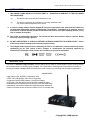
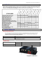
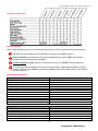
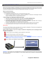
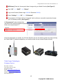
IP Digital H.264 Video Encoder Series Manual Rev. B It’s About Real Time IP Digital H.264 Video Encoder Series Manual Rev-B OWNER’S MANUAL (888) 379-2666 US Toll Free (905) 336-9665 Phone (905) 336-9662 Fax www.VideoTransmitters.com 1 IP Digital H.264 Video Encoder Series Manual Rev. B TABLE OF CONTENTS TABLE OF CONTENTS………………………………………………………………………………………………………..2 SAFETY NOTICE……………………………………………………………………………………………………………….3 INTRODUCTION……..…………………………………………………………………………………………………..3 PARTS LIST…………………………………………………………………………………………………………………….4 PRODUCT DESCRIPTION………………………………………………………………………………………………..4 LED INDICATORS…………....……………………………………………..........……………………………………….4 CONNECTORS, I/O & SLOTS…………………....……………………………………………..........………………….5 DEVICE RESET…………....……………………………………………..........…………………………………………..5 DEFAULT PARAMETERS…………………………………………………………………………………………………5 BASIC CONNECTIONS..………………………………………………..………………………………………………….…6 PC STATIC IP ADDRESS SET-UP…...……………………………………………………………………………………...7 USING WINDOWS XP……………………………....……………………………………………..........………………..7 USING WINDOWS 7………………….………………….……………………………….……………………………….7 INTERNET EXPLORER ActiveX CONTROL……………………………………………………………………………7 LOGIN & PASSWORD ………..………………………………………………………………………………………………8 SETTING NEW LOGIN & PASSWORD....……………………………………………..........…………………………..8 ENCODER IP ADDRESS ………..……………………………………………………………………………………………8 WIDE AREA NETWORK SETUP……………………………………………………………………………………………..9 UPnP™ SET-UP ....……………………………………………..........…………………………………………………..9 WIRELESS NETWORK (WiFi)………………………………………………………………………………………………10 WIRELESS NETWORK SET-UP (Model #IP-720iDVRw & #IPO-720iDVRw ONLY)..........………………………10 3G NETWORK………….……………………………………………………………………………………………………10 WARRANTY STATEMENT……………………….…………………………………………………………………………13 NOTES…………………………………………………………………………………………………………………………15 AVAILABLE DOWNLOADS Visit Us Online Today www.VideoTransmitters.com Central Management Software.exe Central Management Software User Manual – 36 Pages – 2.4Mb Detailed IP Encoder Owner’s Manual - 100 Pages – 4.3Mb 2 IP Digital H.264 Video Encoder Series Manual Rev. B SAFETY NOTICE I. THIS DEVICE COMPLIES WITH FCC RULES PART 15. OPERATION IS SUBJECT TO THE FOLLOWING TWO CONDITONS: (1) This device may not cause harmful interference, and (2) This device must accept any interference, including interference that may cause undesired operation of the device II. In order to comply with the FCC/IC adopted RF exposure requirements, this system will be installed by an authorized professional installer of VideoComm Technologies. Installation of all antennas must be performed in a manner that will provide at least 23cm clearance from the front radiating aperture, to any user or member of the public. III. This is NOT an intrinsically safe device. Do not take into area where intrinsic safety is required. Bodily harm may result if warning is ignored. IV. DO NOT OPERATE WiFi or 3G Devices WITHOUT ANTENNA CONNECTED TO ANTENNA PORT. Failure to do so may result in damage to the unit and void the warranty. V. The IP Digital Video Series has been certified by the FCC for use with other products without any further certification (as per FCC section 2.1091.) Changes or modifications not expressly approved by VideoComm Technologies could void the user’s authority to operate the equipment. INTRODUCTION This series of network IP video encoders converts analog video to allow for remote digital D1 quality viewing, sharing and recording locally or over the internet via laptop, PC or SmartPhone. Boasting many unique features including a remotely accessible embedded DVR, this series is the perfect solution for monitoring and surveillance applications. ADVANTAGES • High quality H.264, MJPEG, D1 Resolution video • NTSC 720 x 480 @ 30fps / PAL 704 x 576 @ 25fps • Included 64 Camera CMS Software - SmartPhone Ready! • PTZ Ready, Two-Way Audio, Motion Detection, Masking & Alarm • Embedded DVR for stand alone recording (SD Card Sold Separately) • Outstanding free technical support and application design assistance • Perfect for network access to remote locations for live or recorded video 3 IP Digital H.264 Video Encoder Series Manual Rev. B PARTS LIST Please inspect the packaging carefully to ensure you have received all the necessary parts and accessories listed. Refer to the following chart to determine which parts are included with your product. If any parts are missing or damaged, contact VideoComm Technologies, Customer Service or your re-seller immediately. PRODUCT DESCRIPTION Minimum System Requirements The H.264 Network IP Video Encoder Series includes an embedded web server which provides users full access to all features and settings through a standard web browser. To access the device settings, your workstation will need to meet the following specifications. CPU Memory Operating System Pentium 4, 2.4Ghz or above 128MB or above Windows XP with SP2 or above, Windows Vista/ Windows 2003 or Windows 7 Internet Explorer 6.0 or above LED INDICATORS: NETWORK PORT (LAN) STATE POWER Amber Green Red Red Solid for Connection Flashes for Network Activity Flashes for Encoder Self-Check Feature Solid for Power Input Indicator 4 IP Digital H.264 Video Encoder Series Manual Rev. B Connectors, I/O & Slots: Device Hard Reset: Each IP Video Encoder includes a convenient Reset button which is used to restore the factory default settings. Disconnect the Power Adapter from the “DC 12V” input plug to power OFF the device. Press and HOLD the reset button by inserting the supplied paper clip into the “RST” terminal while simultaneously reconnecting the power adapter. Continue to HOLD the “RST” button for 15-20 seconds until the red “STATE” LED becomes solid. To confirm a successful Hard Reset, access the Encoder through a standard internet browser using the Default IP Address, Login (888888), and Password (888888). Repeat these steps should you be unable to access the IP device. Device Default Parameters: IP Encoder Parameter IP Address Subnet Mask Gateway Data Transfer Port Data Control Port Remote Reply Port Web Port Multicast Address Multicast Port Remote Host Port Alarm Host Port DNS Server Port Default 192.168.1.19 255.255.255.0 192.168.1.1 3000 3001 3002 80 235.1.1.1 6500 3004 9000 8080 Login and Password Parameter Admin User Name Admin User Pwd Common User 1 Name Common User Pwd Common User Name 2 Common User Pwd Default 888888 888888 1 1 2 2 5 IP Digital H.264 Video Encoder Series Manual Rev. B BASIC CONNECTIONS & SET-UP With so many technical variables in an installation, the strongest recommendation we can make is to conduct a bench test. After verifying that all components of the system are in good working order and connected properly, we can arrive on the job site confident that all of our devices will install with the least amount of on-site effort. Basic Connection Procedure 1. Physical Inspection of Product Compare the unit to the product photo on the attached specification sheet. Check for physical damage to the devices, contact your distributor or VideoComm Technologies Technical Support immediately should you suspect damage to the unit. 2. Bench Testing Your H.264 Network Video Encoder Device Attach the included rubber duck antenna to the Video Encoder (WiFi & 3G Models Only) Connect power, using the supplied power adaptor via the 2.1mm 12VDC barrel jack. Use a separate power supply for each device. Do not share power supplies. Connect the Video Output from the camera to the Encoder using standard BNC-Male cable connectors. Use an RCA-to-BNC adapter if your camera has an RCA connector. Connect the Video Encoder to your network using the standard network cable with a RJ-45 connector. A pre-amplified speaker and microphone can be connected to provide two-way audio if required. Basic Set-up: The H.264 IP Video Encoder must be connected to a PC or Laptop for configuration. The devices are compatible with most operating systems and Internet Explorer 6.0+ browsers. Setting a Static IP address on your PC or Laptop is essential for configuration prior to connecting the Video Encoder to the workstation. Connect IP Device to your workstation using the supplied 3’ network cable Power the IP Device using the 12VDC Plug-In Adaptor Open Internet Explorer browser and enter the default IP address 192.168.1.19 If no connection is made, ensure that your workstations RJ-45 LAN connection is enabled. See your computers “Control Panel“for more details. Enter the Default Login (888888) & Password (888888) WARNING!!: Once Logged into the embedded web server through your internet browser the video screen may appear blank due to restrictions set on your workstation. The video will NOT appear until the settings are configured through your operating system. 6 IP Digital H.264 Video Encoder Series Manual Rev. B PC STATIC IP ADDRESS Using Static IP addresses prevents conflicts between devices on a network and allows you to manage them easily. Assigning a Static IP address to your Windows PC or LAPTOP requires essentially the same process, but the locations of the steps may vary between versions of Windows. Using Windows XP: Open “Control Panel” Select “Network and Internet Connections” Select “Network Connections” Double Click “Local Area Connection” Highlight “Internet Protocol (TCP/IP)” Click the “Properties” button Now Change the IP Address to an available address Click “OK” when complete You MUST close out of the “Network Connection Properties” screen before the changes will take effect Using Windows 7: Open “Control Panel” Select “Network and Internet Connections” Select “Network and Sharing Center” Double Click “Local Area Connection” Select “Properties” Highlight “Internet Protocol Version 4 (TCP/IP V4)” click “Properties” button Now Change the IP Address to an available address Click “OK” when complete (Figure A) You MUST close out of the “Network Connection Properties” screen before the changes will take effect Install Plug Download: Select the “Click Here” link to download the Install plug. Run the Install plug Close the browser. 7 IP Digital H.264 Video Encoder Series Manual Rev. B LOGIN & PASSWORD SET-UP Changing the Video Encoders Login and Password is critical to the security of the device. We strongly recommend that the ‘Admin User’ Login and Password are changed once the device has been configured for network access. The (Admin User) assignment will allow the Administrator Only to configure the device parameters. The (Common Users) are able to view the video but not change or alter any system parameters. Setting New Login & Password: Connect the IP Device to your workstation using supplied 3 ft network cable Power the IP Device using the 12 VDC plug in adaptor Open IE Browser and enter the encoder default IP address Enter the default login and password Select the “Settings” Tab Select the “Basic Parameters” Tab Select the “User Management” Section Enter your new login and password information into fields Admin User Name Admin User Password Verify Click the “OK” button then “Reboot” the encoder to complete the process Login: 888888 Password: 888888 ENCODER IP ADDRESS SET-UP Connect the IP Device to your workstation using supplied 3 ft network cable Power the IP Device using the 12 VDC Plug-In adaptor Open IE Browser and enter the encoder default IP address Enter your new login & password Select the “Settings” Tab Select the “Network Parameters” Tab Select the “IP Address & Ports” Section Ensure that the “Connection Type” selected is “Static IP Address” Change the address to the desired number in the IP Address Field Click the “Save” button then “Reboot” the encoder to complete the process Important!! When selecting a new IP address the last three digits (xxx) should be a number from 1 to 254. It is critical that the IP device is given a unique address that is not used by any other device connected within the same network. 8 IP Digital H.264 Video Encoder Series Manual Rev. B WIDE AREA NETWORK (WAN) SET-UP Now that you have successfully set-up the IP video encoder to your local area network (LAN) the device can be configured to a wide area network (WAN) for remote access enabling multiple authorized users to view live and recorded video at any time and from virtually any networked location in the world. The IP Video Encoders include support for UPnP™ through the embedded web server. This protocol, when enabled, will automatically set up all necessary port forwarding and manage the opening and closing of ports necessary for the IP device to access the Internet. If you choose to not use UPnP or your router does not support it, You must manually configure your router to allow the necessary ports to access the Internet. Ports used by the IP encoder are listed in the Device Defaults on page 5 of this manual. To use UPnP, enable the UPnP function on both the ROUTER and IP ENCODER, the port forwarding settings will automatically change on the reboot of the encoder. NOTE: To manually set up port forwarding, consult you router manual (do not set UPnP to ON in the IP device if you will use manual port forwarding) UPnP™ Set-Up: Open the required network ports in your firewall. Refer to your router operating manual for further instructions. Assuming that the IP device is powered and connected to your workstation, open the IE Browser and enter the encoder IP address Enter your login and password Select the “Settings” Tab Select the “UPnP” Section Select “On” within the “UPnP” pull down menu Click the “OK” button Click the “Save” button then “Reboot” the encoder to complete the process Note: If your workstation (PC or Laptop) is using Windows XP the UPnP interface must be installed. This will ensure that the UPnP function detects the IP device on the network. Figure A: Basic Wide Area Network Connection IP Encoder Network Switch SmartPhone Home 9 Office IP Digital H.264 Video Encoder Series Manual Rev. B WIRELESS NETWORK SET-UP (IP-720IDVRW & IPO-720IDVRW ONLY) The embedded wireless feature allows users to access the IP Video Encoder from nearly any convenient location within the wireless routers networking environment. With minimal initial set-up the Wireless IP Encoders will only require an access point for communication eliminating the need to run complex physical cables to locations saving money in wire, suspended raceways, and labor. Wireless Network Set-Up: Before configuring the WiFi function within the Encoder, ensure that your wireless 902.11 b/g router has the SSID name and encryption programmed. Assuming that the IP device is powered and connected to your workstation, open the IE Browser and enter the encoder IP address. Select the “Settings” “Network Parameters” “WiFi Parameters” Select “Static” within the “Enable WiFi” pull down menu Select “802.11b & 802.11g” within the “WiFi Specifications” pull down menu Click “Refresh” which will auto populate the available wireless networks Select the required wireless network which will appear in the “Current Wireless Network” field Enter the network password into the “Input Password” field and click “OK” Click the “Save” button then “Reboot” the encoder to complete the process 3G NETWORK (Models IP-720iDVR3g & IPO-720iDVR3g ONLY) The 3G Desktop Network IP Video Encoder is perfect for “dead-zone” or remote video applications where there is no local internet infrastructure. Ideal for permanent, temporary or mobile applications from anywhere there is a 3G mobile data network. Important!! Your IP Video Encoder MUST have an Activated SIM Card in order to function and access your 3G Network Services. To purchase and activate a SIM Card and network services, you must contact your preferred Mobile Provider. When activating your SIM card, it is critical that you request a “Static Public IP” Data connection which provides remote access to the Encoder over a 3G Network. 3G NETWORK SET-UP: Eject the SIM Card Tray by inserting a paper clip into the eject port (Figure A) Place SIM Card with the chip facing up on the SIM card tray and push in until secure (Figure B) NOTE: The SIM card is not included and MUST be Purchased and activated from your Mobile service provider Figure A Figure B 10 IP Digital H.264 Video Encoder Series Manual Rev. B Power the IP device using the supplied 12VDC plug-in power adaptor. Ensure that the RED “PWR” LED is Solid to confirm the device is ON. Connect the IP Device to an Enabled RJ45 LAN input on your PC with the included 3’ Network Cable Open an Internet Explorer browser and enter the device IP address (Default 192.168.1.19) Login to the Encoder (Default Login 888888 & Password 888888) Select “Settings” “3G” “3G Online Mode” Select “Always Online” Click “Connect” (See Figure A) Click “Save” “Reboot” Figure A Rebooting will redirect you to the Login Page and may take up to 40 seconds to Reboot. Login to the Encoder (Default Login 888888 & Password 888888) Select “Settings” “3G” “Dial Up Settings” [Link Mode]: Select “ON” via the second pull down (See Figure B) Important!! To ensure that the command has been saved successfully, confirm that the first “Link Mode” field has been automatically changed from “None” to “WCDMA”. If the field does not change, repeat this step until the change is complete. (See Figure C) Click “OK” “SAVE” Figure B Figure C Figure D 11 IP Digital H.264 Video Encoder Series Manual Rev. B [APN Name]: Enter the “Access point Name” assigned by your Mobile Provider (See Figure D) Click “OK” “SAVE” “Reboot” Login to the Encoder (Default Login 888888 & Password 888888) Select “Settings” “3G” “3G Network” Ensure that the “3G Status” field is “Connected” which confirms a successful transmission through your 3G Network provider. (See Figure E) A “Disconnected” status indicated that the device has not been programmed properly. If this occurs repeat steps 4-17 Figure E Once the configuration is complete, the 3G Video Encoder can now be viewed anywhere by simply entering the “Static Public IP” address assigned by your mobile provider into any Internet Explorer browser. VideoComm Technologies Customer Service Bus (905) 336-96651 US Toll Free 888-379-2666 Fax (905) 336-9662 E-mail- [email protected] Web Site- www.VideoTransmitters.com Monday - Friday 8:30am- 5:00pm Eastern Standard Time 12 5.8GHz All Weather 8 Channel Series Manual Rev. M WARRANTY INFORMATION/ TERMS & CONDITIONS VideoComm Technologies, herein referred to as “VCT.” LIMITED WARRANTY VCT hereby warrants, subject to the conditions here in below, that should this product become defective by reason of improper workmanship or material defect during the specified warranty period, VCT will repair the same, effecting all necessary parts without charge for either parts or labor, or replace the unit at VCT option. Labor: ONE (1) Year from the date of original purchase from authorized Re-seller. TWO (2) Years for Antennas only. Parts: ONE (1) Year from the date of original purchase from authorized Re-seller. TWO (2) Years for Antennas only. Void Warranty Purchaser warranty will be void and purchaser waves any rights to make warranty claim if product has been opened, altered or modified, repaired or serviced by anyone, other then the service facilities authorized by VCT to render such services. Further, the seal/serial number on the unit must not have been altered or removed. The unit must not have been subject to accident, misuse, abuse or operated contrary to the instructions provided. The opinion of VCT with respect to this matter shall be final. This warranty does not include and is not extended to broken and damaged accessories, batteries and exposed antennas and to parts wearing out due to normal wear and tear. Proper Delivery: Returned products will not be accepted for warranty repair unless accompanied with a valid Return Merchandise Authorization (RMA) number issued by VCT. RMA numbers issued by VCT are valid for 15 days. Shipments received after 15 days will be refused. The unit must be shipped, freight prepaid or delivered to the VCT Service facility, in either its original package or similar package, affording an equal degree of protection and with instructions indicating the location within Canada or the United States to which the unit will be returned. The repaired unit will be returned to the customer freight prepaid unless the warranty claim is deemed void or invalid. All accessories included with the unit must be listed individually on the packing slip for the shipping documentation. VCT will not accept any liability, for loss or damage to such accessories if they are not listed. Proof of Purchase Date: This warranty applies and commences to VCT products, from the original date of purchase from an Authorized Re-seller. Proof of purchase (i.e.: photocopy of invoice), must be included with product when submitting for warranty repair. Warranty Limitations: This warranty does not cover maintenance or check-ups, if required. This warranty gives you specific legal rights and you may also have other rights, which vary from state/province to state/province. Some states/provinces do not allow the exclusion or limitation of incidental or consequential damages or limitations on how long an implied warranty lasts, therefore the above exclusions or limitations may not apply to you. VCT is not responsible or liable for indirect, special, incidental or consequential damages arising out of or in connection with, the use or performance of the product or other damages with respect to loss of property, loss of revenues or profit, or cost of removal, installation or reinstallation. PRODUCT RETURNS 30 Day Product Return Policy ** If you are not satisfied with a product, you may return it to VCT within 30 days from original date of shipment within the following conditions: Original shipping charges are not refundable unless deemed that VCT shipped incorrect item(s), incorrect quantity (ies) or original manufacturers defective product ( subject to VCT validation ). Returned products will not be accepted unless accompanied with a valid Return Merchandise Authorization number (RMA). RMA numbers issued by VCT are valid for 15 days. Shipments received after 15 days will be refused. Returns must include a copy of original invoice, the completed VCT packing slip, and a detailed statement of reason for return. Customer is responsible for all freight charges, duties and taxes, if applicable. The unit must be shipped, freight prepaid or delivered to the VCT Service facility, in either its original package or similar package, affording an equal degree of protection and with instructions indicating the location within Canada or the United States to which the unit will be returned. prepaid to VCT in its original packaging, or similar packaging that offers an equal degree of protection. VCT will charge the full replacement cost for any missing components or parts. VCT is not responsible for lost or damaged merchandise. We strongly recommend insuring products for return shipping. Return claims are void if manufacturer’s seal is broken and/or products are altered or modified, subjected to an accident, improper handling, improper installation, misuse and abuse or operated contrary to the operating instructions. Products returned that are not in “re-saleable” condition will be returned to customer at their expense. Discontinued items, special or custom-made equipment items (items not carried as stock even though they may appear on price lists) may not be returned. Returned products will be evaluated at the original purchase price and not at any subsequent price increase or decrease. ** Subject to the conditions stated above, the following re-stocking fees will apply to products returned for credit/refund. VCT reserves the right to determine the validity of the product returned and / or refuse to accept product for credit. 0 % Re-Stocking Fee (less original shipping charges): If product is returned within 30 days from original VCT ship date. 25% Re-Stocking Fee (less original shipping charges): If product is returned within 60 days from original VCT ship date. 50% Re-Stocking Fee (less original shipping charges): If product is returned within 90 days from original VCT ship date. 100% Re-Stocking Fee ( 0% credit ) : If product is returned after 90 days from original VCT ship date. DISCLAIMER In no event will VCT or any of its affiliates be liable for any indirect, special, punitive, consequential liability, or incidental damages upon any basis of liability whatsoever even if advised of the possibility of such damages. In addition, VCT does not take any responsibility or assume any liability for the wiring, installation or placement of the equipment Customer purchases, or for the activities of any other individual or entity such as Customer’s Company, those who prepare the specifications or any local Authorities who inspect or approve Customer’s installation. 13 5.8GHz All Weather 8 Channel Series Manual Rev. M 14 5.8GHz All Weather 8 Channel Series Manual Rev. M NOTES 15 5.8GHz All Weather 8 Channel Series Manual Rev. M IT’S ABOUT REAL-TIME Direct 1+(905)336-9665 Toll Free 1+(888)379-2666 www.VideoTransmitters.com 16