1
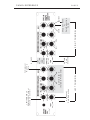
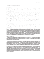
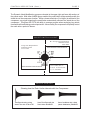
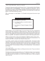
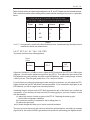
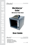
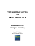
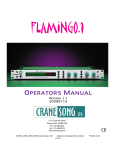
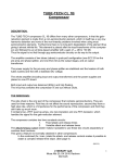
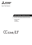
THE STC-8 DISCRETE CLASS A STEREO
COMPRESSOR-PEAK LIMITER
OPERATOR'S MANUAL
Version 1.2
CRANE SONG LTD.
2117 East 5th Street
Superior, WI 54880 USA
tel: 715-398-3627
fax: 715-398-3279
www.cranesong.com
©1996, 2009 Crane Song,LTD.
Subject to change without notice.
Printed in the U.S.A.
IMPORTANT SAFETY INSTRUCTIONS
1. Read these instructions
2. Keep these instructions
3. Heed all warnings
4. Follow all instructions
5. Do not use this apparatus near water
6. Clean only with dry cloth
7. Install in accordance with the manufacturer's instructions
8. Do not install near any heat sources such as radiators, heat registers, stoves, or other
apparatus (including amplifiers) that produce heat
9. Protect the power cord from being walked on or pinched particularly at plugs and the
point where they exit from the apparatus
10. Only use attachments/accessories specified by the manufacturer
11. Unplug this apparatus during lightning storms or when unused for long periods of
time
12. Refer all servicing to qualified service personnel. Servicing is required when the
apparatus has been damaged in any way, such as power-supply cord or plug is damaged, liquid has been spilled or objects have fallen into the apparatus, the apparatus
has been exposed to rain or moisture, does not operate normally, or has been dropped
13. CAUTION: To disconnect the unit completely from the MAINS, unplug the unit. Turning the power switch off does not disconnect the unit completely from the MAINS.
TABLE OF CONTENTS
...........................................PAGE
2
Class A
................................................
Heating and Warm-up
........................... 2
2
PANEL REFERENCE
.....................................
3
CONTROL DESCRIPTION
..............................
Preset Switch Layout
............................. 4
Input/Output GR Graphs
........................ 5
7
DISTORTION AND COMPRESSORS
...............
8
COMPRESSOR QUICK GUIDE
.......................
The "V" Setting
...................................... 9
Preset Settings
..................................... 9
10
FAST SET-UP OF THE PEAK LIMITER ............
10
COMBINED COMPRESSOR LIMITER
..............
The Attack Modulation Decision ............ 11
11
"NUMBERS"
.................................................
Presets
................................................ 11
12
BLOCK DIAGRAM
.......................................
13
INTERFACING
.............................................
14
SPECIFICATIONS
.........................................
15
MODE SWITCH - KI SOUND AND OPTIONS...... 16
INTRODUCTION
PAGE 2
INTRODUCTION
The STC-8 is a high quality compressor combined with a remarkably dependable peak limiter,
that provides overload protection critical to digital recording and broadcast transmitters. The
STC-8’s compressor is engineered to provide musically transparent gain control, but is
also capable of emulating vintage equipment and creating distinctive new sounds.
In addition, a switchable enhancement circuit creates “analog” and “tube-like” warmth to enrich
lifeless audio and digital recordings. This vast flexibility is simplified by the inclusion of several
optimized presets, allowing fast, easy set-up on a wide variety of sounds. It can operate in true
stereo or discrete independent mono, accessible by a front panel switch.
The STC-8’s sophisticated side-chain allows both compression and peak limiting to take place
simultaneously, using the same proprietary gain control circuit. High signal quality is maintained
by utilizing a discrete class A audio path, and by eliminating any VCA or optical gain control
elements.
The STC-8 requires 2 rack spaces. All inputs and outputs are transformer-less and balanced.
The toroidal power transformer is UL approved and allows four line voltages for international use.
The STC-8 delivers consistent gain control without sacrificing musical definition or harmonic richness.
CLASS A DISCRETE TOPOLOGIES
The STC-8 has a Class A audio path which is significantly different than designs that use integrated circuits. Class A circuits sound better because their distortion components tend to be
Second Harmonic; musically pleasing. IC Op-Amps do not have class A output circuits and their
distortion components tend to be high order odd harmonics; not musical. The most important
thing to remember about Class A circuits is that they sound better.
This type of technology has 2 disadvantages when compaired to IC designs. 1) Due to the large
number of parts in discrete circuits; they are costly. 2) Class A circuits run warm.
HEATING AND WARM-UP
The STC-8 must have adequate ventilation. Make sure the vent holes are not blocked. Do
not set anything directly on top of the STC-8. When mounting the STC-8 in a rack, provide as
much air flow as possible. Leaving the back of the rack open is another option. If you provide
adequate ventilation, you will be rewarded with years of reliable operation.
All precision electronic equipment has an operating temperature that when reached will result
in best performance. The STC-8 should be allowed a 10 to 15 minute warm up period before
use.
Slow
(Variable Mode only)
Both
Channels
COLOR
BYPASS
Compressor
Make Up
Gain
ACTIVE IN V
Fast
Slow
LEFT CHANNEL
Amount of
Gain Reduction
Fast
Referenced to output
(Post Gain Control)
LIMITER ONLY
Slow
or
Aggresive
Gain Reduction
Curve
Shape of Knee
Gentle
Slow
RIGHT CHANNEL
Fast
Fast
PANEL REFERENCE
PAGE 3
PAGE 4
CONTROL DESCRIPTION
THRESHOLD
The threshold control governs the amount of gain reduction. The compressor initially has a “softknee” compression curve but is increased by the shape control.
PK THRESHOLD
The peak threshold control sets the level at which the peak limiting takes place. The slope is
greater than 10:1 and is fast enough to prevent overload of a transmitter or digital recorder.
When a signal’s peak is greater than the average gain reduction, the peak circuit will take control
until the peak has passed, and then smoothly transfer regulation back to the compressor. The
green pk LED will light when the peak circuit is active.
When the Pk Threshold Control is set to +20 dBm, the limiter will prevent any increase in output
level above that setting. The output will remain constant even if the gain of the STC-8 is increased. The limiter circuit is post gain control. The dial callibration relates to the maximum
output level.
GAIN CONTROL
The gain control will adjust the compressor gain from 0 to 14 dB of gain. When in stereo link
mode the gain controls operate independently to allow balancing of the stereo program source.
SIDE CHAIN
The side chain consists of two control circuits, one for peak control and one for compression
control. The side chain insert only affects the average or compressor circuits. Due to the design
of the stereo link, separate equalizers (with identical settings) must be used for both channels to
achieve channel matched operation. This scheme allows reliable signal averaging regardless of
the phase relationship between the audio channels. In a conventional stereo link circuit (one EQ
for both channels) out of phase material is ignored by the compressor. This is also beneficial for
stereo FM broadcast where phase relationships can affect the stereo generator.
PRESET SWITCH
The preset rotary switch allows fast and predictable set-up of the STC-8. At first glance this knob
may look a bit forbidding, but in operation, this switch is the key to the flexibility and foolproof
operation of the compressor-limiter.
The STC-8 features two advanced functions: 1)Program Dependent Release (PDR) and 2) Dynamic Attack Modification (A-MOD). The four groups of presets simply give every combination of
these settings. Further, each group has three presets with predetermined, optimized attack,
release and shape settings and one variable setting (which activates the front panel controls).
In the left half of the settings the Program Dependent Release is enabled. This function is especially well suited for leveling the volume of the audio without bringing up background noise. It is
especially helpful controlling voice over, lead vocal and any other complex program material
where short release times tend to bring out room noise and headphone leakage. The right half of
the switch has constant release times, useful for enhancing the sustain of guitars or room ambiance on percussion.
CONTROL DESCRIPTION (Cont.)
PAGE 5
The Dynamic Attack Modification groups are located at the upper right and lower left sections of
the preset matrix. With either A-MOD group enabled, the peak limiter will dynamically modify the
attack time of the compressor function. When a slower attack time (3 or higher) is selected on the
compressor, any signal triggering the peak limiter automatically shortens the attack time of the
compressor. This gives the STC-8 the ability to average program when employing long attack
times while still maintaining overload protection. More notably, the compressor will quickly control
the audio after a period of silence.
PRESET SWITCH LAYOUT
Program Dependent
Release Time
This Side
ATTACK MODIFICATION GROUP
No Program Dependent
Release Time
This Side
ATTACK MODIFICATION GROUP
SETTING KEY:
A,B,C are Presets
V, is Variable
WAVE SHAPES
Showing how the Peak Limiter interacts with the Compressor
Tone Burst showing a long
Attack Time with 12 db of GR
Same Tone Burst with the
Peak Limiter ENABLED
Same Conditions with A-Mod
(Attack Modulation) ENABLED
CONTROL DESCRIPTION (Cont.)
PAGE 6
STEREO LINK SWITCH
When in the link mode the gain control, bypass switches, and meter switches still operate independently. All other functions are operated by the Channel 1 controls.
BYPASS SWITCH
The bypass switch selects the output signal source. When the unit is bypassed all of the compressor circuitry is removed from the audio path. However, the compressor-limiter continues to
operate in a monitoring mode. The unit defaults to the bypass condition when the power is off.
ATTACK CONTROL
The attack control determines the time it takes the compressor to respond to the input signal and
have gain reduction take place. Zero on the control is fast; 10 is slow.
RELEASE CONTROL
The release control sets the time for the compressor’s gain to return to the point of no gain reduction in the absence of program. Zero on the control is fast; 10 is slow.
The attack and release times depend on the shape setting, amount of gain change, settings on
the mode and preset switches, and the program material. They all interact and allow the creation
of a wide variety of sounds that are not possible with any other gain control device available.
MODE SWITCH
The mode switch affects both channels identically. In the HARA position the audio path is transparent. The KI position adds warmth and color and works very well with bass or voice source
material. The audio path and the side chain are modified to get this color change and the effect is
also dependent on the attack, release, and shape control settings.
CONTROL DESCRIPTION (Cont.)
PAGE 7
SHAPE CONTROL
The shape control changes the gain curve, the relationship between amount of gain reduction
taking place and the signal level. The input to output ratio changes as a result of this. With the
control set to 0 the curve and slope are gentle. With the control set to 10 the curve is more
aggressive and the slope is higher.
INPUT/OUTPUT GAIN RELATIONSHIP GRAPH (Graph 1)
In the graph at left, two groups of curves
show gain reduction, groups A and B.
In group A with the input at +25dbm and the
A shape control set at 0, the compressor has an
B
input/output gain relationship that follows the
upper curve with 10db of gain reduction at
the top of the graph. If the shape control is
changed to 10 the STC-8 follows the lower
group A curve with 12.5db of gain reduction
when the input is at +25dbm.
In group B with the input at +25dbm and the
shape control set at 0, the compressor has an
input/output gain relationship that follows the
upper curve with 14db of gain reduction at
the top of the graph. If the shape control is changed to 10, the STC-8 follows the lower group B curve with
18db of gain reduction when the input is at +25dbm.
The shape control settings will influence the attack and release time because of how the gain relationship
changes. In addition to the times, the shape of the attack and release envelopes also change.
INPUT/OUTPUT GAIN RELATIONSHIP GRAPH - LIMITER (Graph 2)
C
D
E
Graph C shows the limiter input/output
gain relationship with no compressor
operation. The Pk Threshold is set at +19
dBm. The graph shows a maximum gain
reduction of 6db when the input is at +25
dBm.
Graph D shows the limiter input/output gain
relationship with no compressor operation.
The Pk Threshold is set at +13 dBm. The
graph shows a maximum gain reduction of
11.5db with an input level of +25 dBm.
Graph E shows a combined compressorlimiter gain curve. The Pk Threshold is set
at +12 dBm. This is the point where the limiter takes over control from the compressor side chain.
In all three cases there is a slight soft knee when the limiter takes control over gain reduction.
CONTROL DESCRIPTION (Cont.)
PAGE 8
METER
The meter has three modes of operation. In the output mode the meter appears as a bar graph.
0 VU is referenced to +4dBm. In the PK mode the meter appears as a dot and shows the amount
of head room by showing peak level below clipping. The third mode shows gain reduction. This
also appears as a dot type display. The red OL LED lights with clipping in the output stage and
the green PK LED lights when the PK side chain takes control from the average side chain. Only
the left channel PK LED is operational in stereo link mode. The meter switch selects what is
being viewed and the mode that the meter operates in.
DISTORTION IN COMPRESSORS
Distortion in compressors is dependent on the RELEASE TIME and the RATIO. The higher the
ratio or the faster the release time, the greater the amount of induced distortion. This distortion
follows the low frequencies and the sound envelope. In all conventional compressors, tube or
solid state, this distortion is third harmonic. The distortion is third harmonic because of the way
the control circuits and gain control elements function.
Third harmonic distortion is a major part of what are called artifacts. Artifacts influence the sound
of the compressor and may or may not be musical. Third harmonic distortion is not a musical
artifact.
The STC-8 has the ability to change the type of induced distortion to second harmonic. In doing
this the non-musical artifact of third harmonic distortion is changed to the musically pleasing
sound of second harmonic distortion. The STC-8 is the only compressor-limiter on the market
that has the ability to change the induced distortion from third harmonic to second.
Changing the induced distortion from third harmonic to second harmonic results in new and
different sounds and adds warmth. This change allows the use of higher compression levels
with fast release times and still have the sound remain musical. This function is enabled on the
STC-8 by putting the MODE SWITCH in the KI position.
PAGE 9
THE COMPRESSOR "QUICK GUIDE"
To set up the Compressor quickly use the Presets A, B, or C. In these modes the Attack, Release,
and Shape controls are not operational. Leave the Pk Threshold in the off position. With Pk
Threshold left in off position, the only decision regarding the Preset Switch is whether or not to use
Program Dependent Release (PDR). PDR is the left half of the Preset Switch, non-PDR is the
right half. (See Preset Switch layout, page 5)
PDR can be thought of as Auto Release. The Threshold control governs the amount of gain
reduction.
CHOOSING PRESET A, B, OR C
A was designed for Vocal sound.
B was designed for Bass or to make the attack of
a sound "Punch".
C was designed for Program Averaging or Volume
Control.
Deciding whether or not to use PDR is easy. Do you want to bring up the "soft" sounds between
words or notes when compressing a voice-like sound (eg. mouth noise, finger noises on an
acoustic guitar)? There are times you will want to bring out these sounds; there are times when
you won't. Using PDR these sounds will remain quiet in volume (depending on release time).
When not using PDR , the in-between sounds will be increased in volume by a greater amount.
PDR is very useful in level or volume control applications. PDR also creates a "softer' sound.
It is best to experiment. Some applications work better with PDR, others are better without. The
bottom line with PDR is to use your ears to determine what you like.
If you desire a "warmer" sound, try the KI position of the Mode Switch. The amount of effect
depends somewhat on the Attack time and mostly on the Release time. Faster settings result in
more effect. The KI position is especially useful on voice, bass, horns, and program. KI warms
the sound by adding second harmonic and gives a sound option that is unavailable in any other
compressor-limiter. KI is most effective in Presets A, B and Variable Mode. It is less effective in
the C Preset.
THE "V" SETTING
In the Variable Setting the Attack, Release, and Shape controls are active. They are not active in
the A, B, or C Preset Settings.
The shape control changes the gain reduction curve. The higher the setting, the more aggressive
the compressor becomes, the higher the ratios become (see graphs 1 & 2 on page 7). If you think
of the GR curve as the knee shape, you can think of the shape control as a way to change the
shape of the knee.
PAGE 10
Table A below shows the relationship between the A, B, and C Presets and the Variable settings.
This is useful information when starting with a preset and then wanting to fine tune for a particular
sound.
APPROXIMATE PRESET SETTINGS AND
THEIR RELATIONSHIP TO THE VARIABLE MODE
Preset
Attack
Release
Shape
A
2
5.5
3.5
B
6.5
6
1
C
6.25
7
5
Table A
*NOTE It is important to note that the Gain Reduction curve , as determined by the shape control,
modifies the attack and release times.
FAST SET-UP OF THE LIMITER
To prevent overload of the following device:
Signal
Source
Oscillator
STC-8
DAT
Machine
Adjust the Oscillator to +16 dBm or more. Adjust the Pk Threshold on the STC-8 for 12db of gain
reduction. Use this as the maximum output from the STC-8. Then adjust the input level on the
DAT Machine to a point just below overload on the DAT Machine. Leave a safety margin of about
1/4db if you can. The ratio gets greater than 10 to 1 but is not infinite.
If you find that you need more make up gain when using the compressor, you can adjust the STC8 gain controls and the DAT will still be overload protected. If you increase the input gain on the
DAT Machine you will no longer have overload protection.
Increasing the gain controls on the STC-8 will increase the ratio of the limiter, but not affect the
compressor. If you find that you have too much Pk Limiting going on, you have 3 options to deal
with the situation;
(1) reduce the amount of make up gain on the STC-8. Reducing the make up gain
will not affect compressor operation.
(2) increase the amount of compression that is taking place, or
(3) reduce the input level.
Any of these changes will allow you to remain overload protected.
The more you know about your gain structure, where the overload point is, and what your average
signal level is, the easier it will be to get maximum level without overloading your digital machine.
PAGE 11
COMBINED COMPRESSOR-LIMITER
When the limiter is set to operate with the compressor, the green peak LED will light when the
limiter takes control. It is recommended that the limiter be used in conjuction with the compressor.
THE ATTACK MODULATION DECISION
Attack modulation (A-Mod) is in the upper right corner and lower left corner on the preset switch
(see Preset Switch layout, page 5). Using A-Mod will help prevent the chopped off limited type of
sound that occurs when a source is peak limited. A-Mod will usually result in a less processed
sound.
A-Mod is also useful in program averaging. When using long attack times a volume suck down
may occur at the beginning of a song because of the time it takes the compressor to bring gain
under control. The A-Mod setting shortens the compressor attack time when the peak threshold
is exceeded. Then it allows the compressor to return to normal operation. By having a shorter
attack time at the start of the song, the compressor quickly controls Gain, avoiding the volume
suck down.
Light to moderate peak limiting will result in transparent peak limiting when the limiter is used in
conjunction with the compressor.
"NUMBERS"
It is very difficult to assign numbers to Attack Time, Release Time, or Ratio. They change
continuously depending on the gain reductiion curve and amount of gain reduction taking place.
Ratio is defined as:
Ratio =
change in input dB
change in output dB
Amount of gain change can be determined by looking at Graph 1 and Graph 2 on page 7. As
evident in the diagrams, the ratio changes at different points on the graph. This change is determined by the amount of gain reduction taking place. The Shape Control changes the gain reduction curve (the shape of the knee). The limiter can also alter that curve. Its like having a second
threshold and knee. As a result of this flexibility there are no fixed numbers.
An important point to remember is that as more gain reduction takes place, the ratio becomes
higher. The ratio becomes higher when the need to control the sound source becomes greater.
By increasing the amount of gain reduction, the louder sound source will automatically cause more
gain reduction.
To increase the ratio, i.e. get tighter control, increase the amount of gain reduction taking place. In
the variable mode, one can also turn up the shape control . Most tube and optical based compressors work like this.
Don't be afraid to make the STC-8 work. It is happy with 12 dB of gain reduction. Experiment, turn
the knobs, find sounds that you like. Numbers are meaningless if the sound is pleasing.
PAGE 12
The following chart is an attempt to show what happens with the A, B, and C Presets. For the
purpose of the measurements in the chart, the compression range is from no gain reduction to 12
dB of gain reduction. Numbers in the chart are approximate. Ratio conditions are as indicated.
*Ratio conditions relate to the entire specific preset section, not to Release Time and Conditons
columns in the chart. i.e. Starting GR and Ratios in the A Preset section relate to the whole section.
Preset
Attack TTime
ime
to 6db of GR
A
B
C
2 mS
12 mS
10 mS
Release TTime
ime
Conditions
for 6db of Gain
Increase
Ratio*
Measured by incr. input by 3dB
Starting GR
Ratio
130 mS
No PDR
6 dB
1.8 to 1
78 mS
PDR signal present
for 128 mS
12 dB
3 to 1
60 mS
PDR signal present
for 32 mS
18 dB
5 to 1
110 mS
No PDR
6 dB
1.9 to 1
90 mS
PDR signal present
for 128 mS
12 dB
2.7 to 1
80 mS
PDR signal present
for 64 mS
18 dB
5.6 to 1
.45 sec
No PDR
6 dB
1.8 to 1
.2 sec
PDR signal present
for 128 mS
12 dB
2.9 to 1
5 sec
PDR signal present
for 10 sec
18 dB
4.5 to 1
PAGE 13
SIGNAL FLOW BLOCK DIAGRAM
Input
Amplifier
INPUT
Post Amplifier
(SINGLE CHANNEL)
Gain Amplifier
Gain
Control
OUTPUT
Side
Chain
Interface
PWM
and
Control
Signal
Combiner
Output
Amplifier
Compressor
Side Chain
Limiter
Side Chain
Meter
Gain
Control
Bypass
Relay
PAGE 14
INTERFACING
Input:
Floating, balanced. Maximum input is +25 dBm.
The connectors are XLR.
Output:
Floating, balanced. Maximum output is +25 dBm.
The connectors are XLR.
For Input and Output : Pin 2 is Sig + , Pin 3 is Sig- , Pin 1 is GND
Side Chain
Connections:
Floating, balanced. Connections are made by using a DB-15
Male Connector. This is a loop insert and must be normaled back
to the STC-8.
SIDE CHAIN CONNECTIONS/PIN OUT CHART
Channel 1 PIN#
Channel 2 PIN#
Output: SIG+
(send) SIG GND
10
11
14
1
9
2
Input: SIG +
5
6
13
8
7
15
(return) SIG -
GND
To enable connect PIN 4 to PIN 3
limiter preset enable PIN 12 to PIN 13
Unbalanced
Connections:
Are made by tying the SIG- Pin to the GND Pin. If the connection is an
input, it is best to tie at the signal source. If the connection is an output, it
is best to tie at the STC-8 connector.
Power:
100, 120, 230,240 volt; 50/60 Hz; 55 watts
MDL .6A Fuse for 100V and 120V
MDL .3A Fuse for 230V and 240V
Pilot Lamp:
# 7335
Shipping
Weight:
19 lbs. (8.6 kg)
Depth
Behind Panel:
12.5 inches (31.75 cm) plus cabling
Panel Height:
2 rack spaces
PAGE 15
SPECIFICATIONS
Compressor
Attack Time:
FAST; measured by doing 18 dB of Gain Reduction. The time to 18 dB of
Gain Reduction is less than 1mS. 12 dB of the 18 are reached in .4mS.
SLOW; for 6 dB of GainReduction, 100mS
Compressor
Release Time:
FAST; From 12 dB of Gain Reduction to No Gain Reduction. 11 of 12 dB
are reached in 50mS (Non Program Dependant Release)
SLOW; 20 sec for a full 12 dB release with PDR enabled.
Limiter
Attack Time:
less than 1uS.
Limiter
Release Time:
60mS for 6 dB of Gain Reduction.
Maximum
Signal Level:
Input or Output, +25 dBm
Noise Floor:
-88 dBm measured 20Hz to 20kHz
Frequency
Response:
5Hz to 55kHz (Hara Mode)
Limiter Slope:
Greater than 10 to 1
LINE VOLTAGE RANGE
Setting
Min. Voltage
Max. Voltage
100V
91V
112V
120V
104V
130V
190V
236V
206V
257V
230V
same as
220V
(
240V
)
PAGE 16
MODE SWITCH - KI SOUND AND OPTIONS
A number of vintage compressors have a frequency response that changes with gain change.
This is a result of changing circuit impedance and is typical of optical based compressors such
as the LA-2A and similar devices. These devices will be flat with no gain reduction and become
bright with gain reduction, or will loose hi end with no gain reduction and become flat with 6 to
12 db of gain reduction. It’s part of their sound and is highly prized by many people. How ever it
may not be what you want depending upon the application.
Part of the KI sound is similar to the above effect and part is a modification of the side chain.
There is a way to change the operation of the STC-8 so that only the side chain is changed in
the KI position of the mode switch. This means that the compression artifacts will become
second harmonic (normal mode of KI) but the audio path will be left transparent. This is done by
changing an internal jumper J3. The normal mode as shipped from the factory is with the effect
enabled.
The following drawing shows the jumper location. It is located close to the center of the main
cicuit board next to a yellow relay. With the jumper on the front 2 pins the HF effect will take
place. With the jumper on the back 2 pins the effect will not be engaged with the mode switch.
J3
If you do this the unit MUST BE FIRST BE DISCONNECTED FROM AC POWER, THE CORD
UNPLUGGED. You should ground your self to the unit before removing the top cover and
remain in physical contact with the unit to prevent static discharge. If you are unsure get a tech.
to change the jumper.
LIMITER SOURCE
J1 and J2 determine the signal source for the peak limiter. The normal mode of operation is on
the two left most pins. This is set so the limiter is referenced to the output, post gain control. It is
recommended that the jumpers be left in this position. Please contact us before changing J1
and J2.
CRANE SONG
LTD.
2117 E. 5th Street
Superior, WI 54880 USA
tel. 715-398-3627
fax. 715-398-3279
STC-8 DISCRETE CLASS A COMPRESSOR-LIMITER
REGISTRATION FORM
Please fill out this form and return it so we can send you updates and
pertinent information as it becomes available.
Thank you.
NAME___________________________________________________
STUDIO NAME___________________________________________
ADDRESS ______________________________________________
CITY___________________________STATE_____ ZIP___________
COUNTRY________________PHONE ________________________
SERIAL # _______________________________________________
DEALER___________________________________________________
PURCHASE PRICE _______________________
EMAIL __________________
WEBSITE_______________________