1
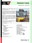
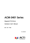
AGAT-SP6
Volumetric Microwave Detector
AGAT-SP6
USER MANUAL
US Toll Free: 1 -886-534-2STR
Phone: +1-416-657-4434
Fax: +1-416-650-9012
www.STRsecurity.com
support@STRs ecurity.com
Revision 1.2_______________________________________________________18.05.2005
User Manual
Page 1
AGAT-SP6
This operating manual contains information regarding purpose, design,
operation, technical specifications and the structure of the volumetric
microwave detector “AGAT - 6”(further “detector”) as well as installation and
usage instructions necessary for providing the most effective application of
its technical potential.
1. Detectors’ main function
The detectors ’ main function is intrusion detection in the protected premise.
The detector may be used outdoors as well.
The size of the detection zone (DZ) can be adjusted.
The detector generates an alarm signal (further “alarm”) in form of opening
its NC output circuit and turning on the indicator when:
- There is a moving human in the detection zone at a no more than 1 m
distance;
- The power is off or less than 10.2V;
The detector generates an alarm in form of opening the tamper switch
contacts when the front cover (which covers the controls) is opened.
The detector requires a 12-24 V DC power supply unit with no more than
0.3V ripple amplitude.
Exploitation conditions:
- Operation temperature range is from -40°C up to + 65°C;
- Relative air humidity of up to100% at +25°C air temperature.
The detector is resistant to the following:
- movement of small animals and birds at 2 or more meters away from the
detector;
- thunderstorm power line fluctuations of up to 1000 V;
- Luminescent lamps in the protected zone.
The detector casing has an anti-dust and a water resistant coating.
User Manual
Page 2
AGAT-SP6
Several detectors may be installed together, with at least a 2m distance
separating them.
2. Main technical specifications
Main technical specifications are listed in Table 1.
Table 1
Parameter
Value
Range of detected speed, m/s
radial direction
From 0.3 up to 3.0
peripheral direction
From 0.3 up to 5.0
Detection zone length at maximum
20+4
range, m
Detection zone maximum area, sq
120
m; at least
Maximum protected zone width, sq
20
m, at least
Detection zone length at minimum
6
range, m, no more than
Power supply voltage range, V
From 10.2 to 27
Power consumption, mA, no more
60
than
Warm-up time after power up, s
30
Signal parameters in alarm and
tamper circuits:
- current (AC or DC), mA, no more
100
than
72
-voltage amplitude, V, no more than
User Manual
Page 3
AGAT-SP6
Alarm signal duration, s, at least
2
Operating frequency, GHz
9.25+/- 0.25
Size (packaged) without initial
105x65x45
assembly kit (IAK), mm
Device weight (pac kaged), kg,
0,45
Average life time, years,
8
3. Detector’s modes of operation
Detector’s modes of operation are listed in Table 2.
Table 2
Mode
Indicator status
Output relay
contacts status
PROTECTION
Off
Closed
ALARM
On (for 2 -30 s)
Opened (2-30
s)
POWER
Flashes at
Constantly
SUPPLY
regular intervals
closed(more
VOLTAGE
(flash duration-
than 30 s)
DEFICIT
1s; period- 2s)
INTERFERENC
Irregularly
E
flashes (flash
closed
duration-0,25 s)
DEFECT
User Manual
Constantly on
Constantly
(more than
opened (more
30s)
than 30 s)
Page 4
AGAT-SP6
Attention! If the front control cover is open, the tamper switch contacts will
open as well.
4. Detector’ delivery kit
The delivery kit of the detector includes:
- Receiver-transmitter (RCR-TMR) - 1 pc;
- Initial assembly kit (IAK) – 1 pc;
-Operating manual;
5. Principle of operation
The detector is a passive Doppler type radio -locator, based on frequency
modulation of emitted signal with adjustment of the signal reflected from
moving objects according to the target distance.
Its core difference from regular Doppler based alarm detector, is a constant
“sensing” of the entire detection zone.
6. Design
The detector includes RCR-TMR and IAK. RCR-TMR (diagram 1) is a oneblock unit with anti-dust and water-resistant casing.
The bracket ensures RCR-TMR can be turned horizontally within the +/- 45
degrees range, and turned vertically – up: at least 45 degrees; down: at
least 25 degrees.
User Manual
Page 5
AGAT-SP6
Diagram 1- Design of the detector
7. Installation site requirements
ATTENTION! STABLE OPERATION OF THE DETECTOR DEPENDS
ON MEETING THE FOLLOWING REQUIREMENTS!
The detector should be installed on vibration free walls at a height of at
least 1.5 m.
Animals, birds, vibrating and moving objects (windows, doors and etc.) are
not allowed in the protected area.
Buildings which have walls, floor or ceiling (wooden, glass etc.) transparent
to radio signals, the size of the detection zone should not exceed the size
of the building. It is recommended to direct the detector towards blank main
walls.
User Manual
Page 6
AGAT-SP6
In case of an outdoor installation, the following requirements should be met:
- Movement of bushes, branches or other objects like gates, old wire
fences and etc (because of wind, for example) is not allowed in the
detection zone;
- Grass level should not exceed 0.2 m;
- Moving transport, people and animals are not allowed in the detection
zone.
- In case of wall mounting, water drainage from rooftops should not be
close to the detector (front distance of at least 2 m; side distance of at least
0.5 m);
- It is recommended to use a fence in the protected area to avoid
accidental crossing of the detection zone by people or animals.
- The location of the installation should be at least 2 m away from areas of
possible animal movement and bird nesting/perching.
Take into consideration the fact, that a signal reflected from a moving
human depends on the sight perspective (the area of the observed shape).
For example, signal from a person observed from above is 2-3 times
weaker, than the signal from the same person observed from the front or
from the side. The shape of a person observed from above is comparable
with the shape of a medium sized dog, severely affecting the ability to
differentiate between them.
To avoid water flow forming a coating on the emitting surface during
heavy rainfall causing false alarms the detector should be installed
under a cover or protective visor.
8. Installing the detector
Mark the selected location, drill 5 mm holes and install anchors from ISA in
the holes (anchors should not be installed in wooden walls). Fasten
User Manual
Page 7
AGAT-SP6
bracket to the wall with screws. The RCR-TMR should be installed in a way
where the detectors’ front cover is aligned with the detection zone axis.
An example of connecting the detector to alarm control panel is shown on
diagram 2. Terminal zone resistor R is connected to the socket which is
placed under the control cover.
RCR_TMR
R
Socket
+
−
NC
«+»
«−»
TS
«NC»
«TS»
«NC»
«TS»
To PSU
To Alarm Control Panel
Diagram 2. Detector connection chart with joint output and tamper circuits.
Detector wiring is listed in Table 3.
Table 3
#
Marking of contact
Function of
contact
1
+
Power supply
“Positive ”
2
-
Power supply
“Negative ”
User Manual
Page 8
AGAT-SP6
3,4
??
Output relay
contacts
5,6
??
Tamper switch
contacts
9. Preliminary actions and detector adjustment
9.1 Apply power voltage to the detector and check voltage on the respective
cord outlets. Apply power to the detector and check voltage on the
respective contact. Measured value should be in the 11.5 -27 V range
9.2 Take off the front control cover, set sensitivity adjustment jumper in the
middle position and check indicator status. In there are no moving objects
in the detection zone, 15 s after power up, the indicator should be off,
which corresponds to the PROTECTION mode of operation.
9.3 Set the required detection distance with distance adjustment resistor
control (should be checked with test crossing). The counter-clockwise up
to stop position of the resistor control corresponds to the minimum
distance range.
9.4. Detector sensitivity should be set as follows:
a) Set sensitivity jumper to the bottom position;
b) Enter the detection zone center and stand motionless until the indicator
stops flashing (about 15 s). Check the detection (alarm generation) moving
while bent, or crawling along the detection zone axis at a speed of 1-2 m/s
towards the detector, at no more than 1 m distance.
c) Repeat b) at least 3 times.
d) If an alarm signal is not generated, b) and c) should be repeated and
sensitivity consecutively increased by setting sensitivity jumper in higher
positions. Try to achieve alarm signal generation on every crossing.
User Manual
Page 9
AGAT-SP6
9.5 After setting the sensitivity, check the detection distance and, if needed,
adjust the distance according to 9.3 instructions.
9.6 If the detector is installed on premises with walls, floors or ceilings
transparent to radio signals, please check the detectors’ sensitivity towards
people moving outside the protected area. If detections are generated in
case of people moving in adjacent areas, the detection distance should be
decreased or detectors ’ orientation changed.
9.7 Reinstall the controls cover and check detector’s normal operation
(check alarm signal being transferred to the alarm control panel, during a
detection zone crossing test).
ATTENTION! MINIMAL NECESSARY DISTANCE AND SENSITIVITY
VALUES
SHOULD
BE
SET,
TO
ENSURE
THE
REQUIRED
DETECTION ZONE SHAPE IS PRESENT! DETECTION ZONE SIZE
SHOULD NOT BE INCREASED BY INCREASING THE SENSITIVITY
SINCE IT WOULD CAUSE LOSS OF NOISE PROTECTION!
10. List of possible defects and troubleshooting
Possible defects and troubleshooting are listed in Table 4.
Table 4
Defect
Possible
Troubleshooting
reasons for
defect
1.NC contacts
Power
supply
Check power supply
of output circuit
voltage
below
voltage. On absence
are
normal value
constantly
or low voltage check
open (over 30
power supply
s), indicator is
connection cable
not on
and PSU.
Detector
defective
User Manual
is
Detector should
be replaced
Page 10
AGAT-SP6
2. NC contacts
Control panel
Disconnect
of output circuit
alarm zone
terminal resistor
are constantly
terminal
from alarm
open (over 30
resistor is
control panel
s), indicator is
damaged.
and check it.
Controls cover
Check if the
improper
cover was
installation.
installed
not glowing
constantly, but
giving short
flashes (from 2
properly.
up to 30 sec)
Detector is
Detector should
defective
be replaced.
3. NC contacts
Low power
Check
power
of output circuit
supply voltage
supply
voltage.
while crossing
the detection
zone
are
constantly
On absence or
open (over 30
low
voltage
s) the indicator
check
displays
supply
POWER
connection
SUPPLY LOW
cable and PSU.
power
.
4. Detector
Detector
has
Visually
check
does not
not been used
the
compliance
generate alarm
in accordance
of
installation
signal during
with operating
and
detection zone
manual
conditions
crossing test.
requirements.
sections 1 and 7
usage
with
of this manual.
Detector
has
been adjusted
User Manual
Check
compliance
the
of
Page 11
AGAT-SP6
incorrectly
installation
with
section
9
instructions.
Detector
is
defective
Detector should
be replaced.
5. False alarms
Detector
has
Visually
check
are generated
not been used
the
compliance
too often
in accordance
of
installation
with operating
and
manual
conditions
requirements.
sections 1 and 7
usage
with
of this manual.
Unstable
Check
power
supply
or
supply
too
high
power
connection
ripple
cable and make
amplitude.
sure that there
are
no
strong
interference
sources in the
vicinity.
Check
PSU
operation
-
perform
running
test
of
the
detector using a
different PSU.
User Manual
Defective
With
jumpers
terminal
connect NC and
resistor circuit
tamper
switch
Page 12
AGAT-SP6
output
circuits
and perform test
running.
alarm
False
signals
registered
alarm
by
control
panel are sign of
defective
terminal resistor
or alarm control
panel.
Detector
defective
is
Detector should
be replaced
Notice!
1. An actual detector defect should be determined by installing a new
detector and performing test runs.
2. After completing the troubleshoot the detector should be adjusted
according to section 9 instructions.
User Manual
Page 13
AGAT-SP6
Warranty Information / Terms & Conditions
STR International Inc herein referred to as “STR.”
LIMITED WARRANTY
STR hereby warrants, subject to the conditions here in below, that should this product become defective by
reason of improper workmanship or material defect during the specified warranty period, STR will repair the
same, effecting all necessary parts without charge for either parts or labor, or replace the unit at STR option.
Labor: ONE (3) Years from the date of original purchase from authorized Re -seller unless otherwise specified.
Parts: ONE (1) Year from the date of original purchase from authorized Re-seller unless otherwise specified.
Void Warranty
Purchaser warranty will be void and purchaser waves any rights to make warranty claim if product has been
opened, altered or modified, repaired or serviced by anyone, other then the service facilities authorized by STR
to render such services. Further, the seal/serial number on the unit must not have been altered or removed. The
unit must not have been subject to accident, misuse, and abuse or operated contrary to the instructions provided.
The opinion of STR with respect to this matter shall be final. This warranty does not include and is not extended
to broken and damaged accessories, batteries and to parts wearing out due to normal wear and tear.
Proper Delivery:
Returned products will not be accepted for warranty repair unless accompanied with a valid Return Merchandise
Authorization (R MA) number issued by STR. RMA numbers issued by STR are valid for 15 days. Shipments
received after 15 days will be refused. The unit must be shipped, freight prepaid or delivered to the STR service
facility, in either its original package or similar package, affording an equal degree of protection and with
instructions indicating the location within Canada or the United States to which the unit will be returned. The
repaired unit will be returned to the customer freight prepaid unless the warranty claim is deemed void or
invalid. All accessories included with the unit must be listed individually on the packing slip for the shipping
documentation. STR will not accept any liability, for loss or damage to such accessories if they are not listed.
Proof of Purchase Date:
This warranty applies and commences to STR products, from the original date of purchase from an Authorized
Re-seller. Proof of purchase (i.e.: photocopy of invoice), must be included with product when submitting for
warranty repair.
Warranty Limitations:
This warranty does not cover maintenance or check-ups, if required. This warranty gives you specific legal rights
and you may also have other rights, which vary from state/province to state/province. Some states/provinces do
not allow the exclusion or limitation of incidental or consequential damages or limitations on how long an
implied warranty lasts, therefore the above exclusions or limitations may not apply to you. STR is not
responsible or liable for indirect, special, incidental or consequential damages arising out of or in connection
with, the use or performance of the product or other damages with respect to loss of property, loss of revenues or
profit, or cost of removal, installation or reinstallation.
User Manual
Page 14
AGAT-SP6
PRODUCT RETURNS
30 Day Product Return Policy ** If you are not satisfied with a product, you may return it to STR within 30 days
from original date of shipment within the following conditions:
? Original shipping charges are not refundable unless deemed that STR shipped incorrect item(s), incorrect
quantity (ies) or original manufacturers defective product ( subject to STR validation ).
? Returned products will not be accepted unless accompanied with a valid Return Merchandise Authorization
number (RMA).
? RMA numbers issued by STR are valid for 15 days. Shipments received after 15 days will be refused.
? Returns must include a copy of original invoice, the completed STR packing slip, and a detailed statement of
reason for return.
? Customer is responsible for all freight charges, duties and taxes, if applicable. Product must be properly
packaged and shipped, Prepaid to STR in its original packaging, or similar packaging that offers an equal
degree of protection. STR will charge the full replacement cost for any missing components or parts. STR is not
responsible for lost or damaged merchandise. We strongly recommend insuring products for return shipping.
? Return claims are void if manufacturer’s seal is broken and/or products are altered or modified, subjected to an
accident, improper handling, improper installation, misuse and abuse or operated contrary to the operating
instructions. Products returned that are not in “re-saleable” condition will be returned to customer at their
expense.
? Discontinued items, special or custom -made equipment items (items not carried as stock even though they
may appear on price lists) may not be returned. Returned products will be evaluated at the original purchase
price and not at any subsequent price increase or decrease.
** Subject to the conditions stated above, the following re-stocking fees will apply to products returned for
credit/refund.
STR reserves the right to determine the validity of the product returned and / or refuse to accept product for
credit.
0 % Re-Stocking Fee (less original shipping charges): If product is returned within 30 days from original STR
ship date.
25% Re-Stocking Fee (less original shipping charges): If product is returned within 60 days from original STR
ship date.
50% Re-Stocking Fee (less original shipping charges): If product is returned within 90 days from original STR
ship date.
100% Re-Stocking Fee ( 0% credit ) : If product is returned after 90 days from original STR ship date.
DISCLAIMER
In no event will STR or any of its affiliates be liable for any indirect, special, punitive, consequential liability, or
incidental damages upon any basis of liability whatsoever even if advised of the possibility of such damages. In
addition, STR does not take any responsibility or assume any liability for the wiring, installation or placement of
the equipment Customer purchases, or for the activities of any other individual or entity such as Customer’s
Company, those who prepare the specifications or any local Authorities who inspect or approve Customer’s
installation.
PRIVACY POLICY
User Manual
Page 15
AGAT-SP6
STR does not collect personally identifying information about you except when you specifically provide it to us.
Forms you may fill out that request personal information such as your mailing address, telephone number, email address, etc. will not be disclosed to any third party companies.
www.STRsecurity.com is for information purposes. Distribution, duplication, modification or revision of the
contents of this site is strictly prohibited without the explicit written permission of STR.
STR is committed to safeguarding your privacy online. We only use your personal information to service your
account, to provide you with the products you inquire about and request, and to inform you of additional
products or services that may benefit you.
User Manual
Page 16